
NV65HMC - Stapler HiKOKI - Free user manual and instructions
Find the device manual for free NV65HMC HiKOKI in PDF.
| Brand | HiKOKI |
| Model | NV65HMC |
| Product type | Pneumatic stapler |
| Operating type | Reciprocating piston |
| Recommended air pressure | 12 – 23 bar |
| Maximum allowable pressure | 26 bar |
| Dimensions (L × W × H) | 266 × 130 × 285 mm |
| Weight | 2.0 kg |
| Magazine capacity | 200 – 400 staples (1 coil) |
| Internal hose diameter | 5 – 6 mm |
| Compatible staple types | Wire coil or plastic band, head diameter 4.8 – 7.3 mm |
| Firing mechanism | Single sequential activation |
| Depth adjustment | Yes, by dial (up to 3 mm) |
| Adjustable exhaust direction | Yes, rotation of top cover |
| Integrated blow nozzle | Yes |
| Removable muzzle cap | Yes (supplied) |
| Recommended lubrication | SHELL TONNA oil or SAE 10W/20W |
| Sound pressure level (L_pA) | 88.1 dB(A) (uncertainty 2.5 dB) |
| Sound power level (L_WA) | 95.0 dB(A) (uncertainty 2.5 dB) |
| Vibration value (a_h) | 2.9 m/s² (uncertainty 1.5 m/s²) |
| Included accessories | Safety glasses, oiler, tip cap |
| Applications | Wood, framing, crates, pallets, packaging |
| Maintenance | Regular cleaning and lubrication |
Frequently Asked Questions - NV65HMC HiKOKI
User questions about NV65HMC HiKOKI
0 question about this device. Answer the ones you know or ask your own.
Ask a new question about this device
Download the instructions for your Stapler in PDF format for free! Find your manual NV65HMC - HiKOKI and take your electronic device back in hand. On this page are published all the documents necessary for the use of your device. NV65HMC by HiKOKI.
USER MANUAL NV65HMC HiKOKI
natural_image
Technical line drawing of a mechanical device with no visible text or symbolsRead through carefully and understand these instructions before use.
2

3

4

5

6

7

8
9
10

11
12 13
natural_image
Line drawing of a hand operating a power tool on a rail track (no text or symbols)2

natural_image
Line drawing of a hand using a power tool to adjust or install a mechanical component (no text or symbols present)1
14 15

16 17

18 19


20 21

22
23

24 25


26

natural_image
Line drawing of a mechanical device with a circular top and arched base, labeled with number 52 (no text or symbols beyond label)| Svenska Dansk Norsk | |||
| 1 | Blåsmunstyckesomkopplare Blæsed | yseknap Luftdyseknapp | |
| 2 | Utblåsningsskydd Udstødsdække Utblåsningsdeksel | ||
| 3 | Hölje Værktøjshus Hus | ||
| 4 | Hylsa Dæksel Kappe | ||
| 5 | Luftplugg Luftstik Luftplugg | ||
| 6 | Blåsmunstyckets luftutlopp Blæserdysens luftudgang Luftavløp til luftdyse | ||
| 7 | Noshylsa Næsekappe | Frontkappe | |
| 8 | Kolv | Stempel | Stempel |
| 9 | Ventil | Venti | Ventil |
| 10 | Avtryckare | Udløser | Avtrekker |
| 11 | Låsarm Låsearm | Låsearm | |
| 12 | Spärrläge | Låst position | Låst posisjon |
| 13 | Fritt läge | Fri position | Åpen posisjon |
| 14 | Knopp | Drejeknap | Knott |
| 15 | Spikstyrning | Søm-styr | Spikerføring |
| 16 | Magasin | Magasin | Magasin |
| 17 | Spikhållare | Sømholder | Spikerholder |
| 18 | Magasinhölje | Magasindække | Magasindeksel |
| 19 | Dammkåpa | Støvdæksel | Støvdeksel |
| 20 | för 32 mm | For 32 mm | For 32 mm |
| 21 | för 38 mm och 40 mm | For 38 mm og 40 mm | For 38 mm og 40 mm |
| 22 | för 45 mm och 50 mm | For 45 mm og 50 mm | For 45 mm og 50 mm |
| 23 | för 57 mm och 65 mm | For 57 mm og 65 mm | For 57 mm og 65 mm |
| 24 | Spikar | Søm | Spiker |
| 25 | Första spiken | Første søm | Første spiker |
| 26 | Utlopp | Udgang | Uttak |
| 27 | Spärrhake (1) | Pal (1) | Sperre (1) |
| 28 | Spärrhake (2) | Pal (2) Sperre (2) | |
| 29 | Styrspalt | Styreåbning | Føringsspor |
| 30 | Styrspalt för plastband | Styreåbning til plasticstrimmel | Føringsspor for plastplate |
| 31 | Justerare Regulator | Regulator | |
| 32 | Kort djup | Mindre dyb | Grunn |
| 33 | Långt djup | Dyb | Dyp |
| 34 | Plan | I plan | Jevnt |
| 35 | För djupt | For dybt | For dypt |
| 36 | För grunt | For højt | For grunt |
| 37 | Utblåsventil | Luftafgang | Eksosventil |
| 38 | Ta bort damm | Fjern støv | Fjern støv |
| 39 | Skiva | Strimmel | Plate |
| 40 | Hammare | Hammer | Hammer |
| 41 | Stång | Stang | Stang |
| 42 | Spårskruvmejsel | Skruetrækker med indhak Flat skrutrekker | |
| 43 | Tryckarm Udløserarm | Støtstang | |
| 44 | Spikstoppare (A) Sømstopper (A) Spikerstopper (A) | ||
| 45 | Spikstoppare (B) Sømstopper (B) Spikerstopper (B) | ||
| 46 | Bakre kåpa Endedæksel Bakdeksel | ||
| 47 | Frammatare Sømfremfører Mater | ||
| 48 | Axel Skaft Skaft | ||
| 49 | Hävarm för nosväxling Næseskiftgreb | Vekslespak for spiss | |
| 50 | "Stort" utlopp "Stor" udgang "Stort" uttak | ||
| 51 | "Litet" utlopp | "Lille" udgang "Lite" uttak | |
| 52 | Ljuddämpare Lyddæmper | Lyddemper | |
| 53 | Hål | Hul | Hull |
| 54 | Indrivningsområde (insida) | Tap (på indersiden) | Utstikkende del (innvendig) |
| 55 | Övre höljeSuomi English Français | Topdæksel | Toppdeksel |
| ① | Puhallussuuttimen nuppi | Blow nozzle knob | Bouton de tuyère de souffl age |
| ② | Pakokansi | Exhaust Cover | Couvercle d'échappement |
| ③ | Runko | Body | Corps |
| ④ | Suojus | Cap | Capuchon |
| ⑤ | Ilmapistoke | Air plug | Bouchon d'air |
| ⑥ | Nokan ilmalähtö | Air outlet of blow nozzle | Sortie d'air de tuyère de souffl age |
| ⑦ | Kärkisuojus | Nose cap | Capuchon de museau |
| ⑧ | Mäntä | Piston | Joint torique du piston |
| ⑨ | Venttiili | Valve | Valve |
| ⑩ | Laukaisin | Trigger | Gâchette |
| ⑪ | Lukkovipu | Lock lever | Levier de verrouillage |
| ⑫ | Lukitusasento | Lock position | Position de verrouillage |
| ⑬ | Käyttöasento | Free position | Position libre |
| ⑭ | Nuppi | Knob | Bouton |
| ⑮ | Naulaohjain | Nail guide | Guide-clous |
| ⑯ | Makasiini | Magazine | Magasin |
| ⑰ | Naulanpidin | Nail holder | Porte-clous |
| ⑱ | Makasiinin kansi | Magazine cover | Couvercle du magasin |
| ⑲ | Pölykansi | Dust cover | Couvercle à poussière |
| ⑳ | 32 mm | For 32 mm | Pour 32 mm |
| ㉑ | 38 mm ja 40 mm | For 38, 40 mm | Pour 38, 40 mm |
| ㉒ | 45 mm ja 50 mm | For 45, 50 mm | Pour 45, 50 mm |
| ㉓ | 57 mm ja 65 mm | For 57, 65 mm | Pour 57, 65 mm |
| ㉔ | Naulat | Nails | Clous |
| ㉕ | Ensimmäinen naula | First nail | Premier clou |
| ㉖ | Lähtö | Outlet | Sortie |
| ㉗ | Kiinnike (1) | Pawl (1) | Cliquet (1) |
| ㉘ | Kiinnike (2) | Pawl (2) | Cliquet (2) |
| ㉙ | Ohjainaukko | Guide slot | Fente-guide |
| ㉚ | Muovikamman ohjainaukko Guide slot for plastic sheet | Fente de guidage pour feuille de plastique | |
| ㉛ | Säädin | Adjuster | Ajusteur |
| ㉜ | Matala | Shallow | En superfi cie |
| ㉝ | Syvä | Deep | En profondeur |
| ㉞ | Tasainen | Flush | Normal |
| ㉟ | Liian syvä | Too deep | Trop profond |
| ㉟ | Liian matala | Too shallow | Trop en superfi cie |
| ㉟ | Ilmanpoistoaukko | Exhaust vent | Event d'échappement |
| ㉟ | Poista pöly | Remove dust | Dépoussiéreur |
| ㉟ | Kampa | Sheet | Feuille |
| ㉟ | Vasara | Hammer | Marteau |
| ㉟ | Tappi | Rod | Tige |
| ㉟ | Talttapääruuvimeisseli | Slotted screwdriver | Tournevis plat |
| Suomi English Français | |||
| 43 | Painovipu | Push lever | Levier -poussoir |
| 44 | Naulankiinnitin (A) | Nail stopper (A) | Butée des clous (A) |
| 45 | Naulankiinnitin (B) | Nail stopper (B) | Butée des clous (B) |
| 46 | Päätykansi | Tail cover | Couvercle de la queue |
| 47 | Syötin | Feeder | Chargeur |
| 48 | Akseli | Shaft | Arbre |
| 49 | Nokan kytkinvipu | Nose switch lever | Commande de museau |
| 50 | Lähtö "suuri" | Outlet "Large" | "Grande" sortie |
| 51 | Lähtö "pieni" | Outlet "Small" | "Petite" sortie |
| 52 | Äänenvaimennin | Muffl er | Pot d'échappement |
| 53 | Aukko | Hole | Trou |
| 54 | Ulostyöntyvä osa (sisällä) | Protruding section (inside) | Section saillante (intérieur) |
| 55 | Yläkansi | Top cover | Couvercle supérieur |
ALLMÄNNA SÄKERHETSFÖRESKRIFTER FÖR ELVERKTYG

WARNING
4. Drive spiker inn i betong ADVARSEL
INSPEKSJON OG VEDLIKEHOLD
ADVARSEL
$$ _ {P A} \text { L1s,d } = 8 8, 1 \mathrm{dB} $$
Usikkerhet K: 2,5 dB (A)
Read all safety warnings, instructions, illustrations and specifications provided with this power tool.
Failure to follow all instructions listed below may result in serious injury.
Save all warnings and instructions for future reference.
- Operate the power tool safely for correct uses.
Do not use the power tool for uses other than those specified in this instructions.
- For safe operation handle the power tool correctly.
Please follow the instructions given in this instruction manual and correctly handle this tool so as to ensure safe operation. Never let the tool be use by children or people who do not know enough to be able to handle it correctly, or let it be used by people who cannot operate it correctly.
- Confi rm the safety of the workshop.
Keep unauthorized people away from the workshop. Especially children should be kept away.
- The right parts in the right places.
Do not remove any of the covers or screws. Keep them in place as they have their functions.
Moreover, because it would be dangerous, never make modifi cations to the tool or use it after making modifi cations.
- Check the tool before using it.
Before using the tool, always check that no parts of it are broken, that all screws are completely tight, and that no parts are missing or rusty.
- Excessive work could cause accidents.
Do not make tools and accessories work beyond their abilities. Excessive work not only damages the power tool but also is dangerous in itself.
- Stop operation immediately if abnormalities are noticed.
Stop operation if you notice abnormalities, or if the power tool does not work properly; have the power tool inspected and serviced.
- Look after the power tool carefully.
If you drop or knock the power tool against things, the outer frame may be deformed and cracks or other kinds of damage may occur, so please handle it with sufficient care. Also, do not scratch or engrave signs on the power tool. Owing to high pressure air inside the tool, cracks in the surface are dangerous.
Never use the power tool if a crack develops or if air is escaping from a crack.
- Take good care for a long life.
Always take good care of the power tool and keep it clean.
- Inspection at regular intervals is essential for safety.
Inspect the power tool at regular intervals so that the power tool can be operated safety and efficiently at all times.
- Consult an authorized service agent if repair or parts replacement is necessary.
Ensure that the power tool is serviced by authorized service agent only, and that only genuine replacement parts are used.
- Keep the power tool in a proper place.
When not in use, the power tool should be kept in a dry place out of the reach of children. Put into the body about 2cc oil through the hose joint to protect the tool from rust.
-
The exploded assembly drawing on this handling instructions should be used only for aut service center.
-
Hold the tool with a fi rm grasp and be prepared to manage recoil.
-
Store idle power tools out of the reach of children and do not allow persons unfamiliar with the power tool or these instructions to operate the power tool.
Power tools are dangerous in the hands of untrained users.
-
Do not modify the fastener driving tool. Modifications may reduce the effectiveness of safety measures and increase the risks to the operator and/or bystander
-
Maintain power tools and accessories. Check for misalignment or binding of moving parts, breakage of parts and any other condition that may affect the power tool's operation. If damaged, have the power tool repaired before use.
Many accidents are caused by poorly maintained power tools.
- Do not overreach. Keep proper footing and balance at all times.
This enables better control of the power tool in unexpected situations.
- Keep children and bystanders away while operating a power tool.
Distractions can cause you to lose control.
PRECAUTIONS ON USING NAILER
- Safe operation through correct usage
This tool was designed for driving nails into wood and similar materials. Use it for its intended purpose only.
- Make sure air pressure is within the rated range of air pressure.
Please make sure that the air pressure is within a range of 12 bar – 23 bar (170 \~ 320 psi), and that the air which is used is clean and dry. If the air pressure is greater than 23 bar (320 psi), the life of the power tool will be shortened and dangerous conditions could develop. Tools shall not be connected to pressure which potentially exceeds 26 bar (370 psi).
- Never operate the equipment with high-pressure gases other than compressed air.
Never use carbon dioxide, oxygen or another gas from pressurized containers under any circumstances.
- Be careful of ignition and explosions.
Since sparks may fly during nailing, it is dangerous to use this tool near lacquer, paint, benzine, thinner, gasoline, gas, adhesives and similar inflammable substances as they may ignite or explode. Under no circumstances should this tool therefore be used in the vicinity of such inflammable material.
- Always wear eye protection (protective goggles).

When operating the power tool, always wear eye protection, and ensure that surrounding people wear eye protection too.
The possibility of fragments of the wire or plastic linking the nails or nails that were only hit entering the eye is a threat to sight. Eye can be bought at any hardware store. Always protection while operating this tool. Use either action or a wide vision mask over prescription
Employers should always enforce the use of eye protection equipment.
6. Protect your ears and head.

When engaged in nailing work please wear ear mufflers and head protection. Also, depending on condition, ensure that 14 surrounding people also wear ear mufflers and head protection. Unprotected exposure
to high noise levels can cause permanent, disabling, hearing loss and other problems such as tinnitus (ringing, buzzing, whistling or humming in the ears).
Risk assessment and implementation of appropriate controls for these hazards are essential.
Appropriate controls to reduce the risk may include actions such as damping materials to prevent workpieces from "ringing".
Operate and maintain the tool as recommended in these instructions, to prevent an unnecessary increase in noise levels.
7. Pay attention to those working close to you.
It would be very dangerous if nails that were not properly driven in should hit other people. Therefore, always pay attention to the safety of the people around you when using this tool. Always make sure that nobody's body, hands or feet are close to the nail outlet.
8. Never point the nail outlet towards people.
Always assume the tool contains fasteners.
If the nail outlet is pointed towards people, serious accidents may be caused if you mistakenly discharge the tool. When connecting and disconnecting the hose, during nail loading or similar operations, be sure the nail outlet is not pointed towards anyone (including yourself). Even when no nails are loaded at all, it is dangerous to discharge the tool while pointing it at someone, so never attempt to do so. No horseplay. Respect the tool as a working implement.
9. Before using the power tool, check the push lever.
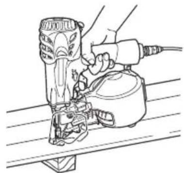
You may rest the tool on a level surface as shown in Fig. 12.
Be sure not to apply the force downward onto the tool to the extent that the push lever is engaged.
Before using the power tool make sure to check that the push lever and valve operate properly. Without nails loaded into the power tool, connect the hose and check the following. If the sound of operation occurs this indicates a fault, so in such a case do not use the power tool until it has been inspected and repaired.
○ If merely pulling the trigger causes operating sound of drive bit movement occur, the power tool is faulty.
○ If merely pushing the push lever against the material to be nailed causes the sound of drive bit movement to occur, the power tool is faulty. Furthermore, with regard to the push lever, please note never be modified or removed.
10. Use specifi ed nails only.
Never use nails other than those specified and described in these instructions.
11. Do not modify the fastener driving tool.
Modifications may reduce the effectiveness of safety measures and increase the risks to the operator and/or bystander.
12. Be careful when connecting the hose.
When connecting the hose and loading nails in order not to fi re the tool by mistake, make sure of the following.
Do not touch the trigger.
○ Do not allow the firing head to contact with any surface.
- Keep the firing head down.
Strictly observe the above instructions, and always make sure that no part of the body, hands or legs is ever in front of the nail outlet.
- Be careful when handling fasteners, especially when loading and unloading, as the fasteners have sharp points which could cause injury.
- Do not carelessly place your finger on the trigger. Do not place your finger on the trigger except when actually nailing. If you carry this tool or hand it to someone while having your finger on the trigger, you may inadvertently discharge a nail and thus cause an accident.
- Completely Close the nail guide and do not open it during operation.
If nailing is attempted when the nail guide is open, nails will not be driven into the timber, and there is a risk of dangerous discharge.
- Press the nail outlet firmly against the material to be nailed.
When driving in nails, press the nail outlet firmly against the material to be nailed. If the outlet is not applied properly, the nails may rebound.
- Keep hands and feet away from the firing head when using.
It is very dangerous for a nail to hit the hands or feet by mistake.
- During operation, debris from workpiece and fastening/collation system may be discharged.
19. Beware of the tool's kickback
Do not approach the top of the tool with your head etc. during operation. This is dangerous because the tool may recoil violently if the nail currently being driven in comes into contact with a previous nail or a knot in the wood.
- Take care when nailing thin boards or the corners of wood.
When nailing thin boards, the nails may pass right through, as may also be the case when n corners of wood due to deviation of the nails. In such cases, always make sure that there is no one (and nobody's hands or feet; etc.) behind the thin board or next to the wood you are going to nail.
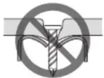
21. Simultaneous nailing on both sides of the same wall is dangerous
Under no circumstances should nailing be performed on both sides of a wall at the same time. This would be very dangerous since the nails might pass through the wall and thus cause injuries.
22. Do not use the power tool on scaffoldings, ladders.
The power tool shall not be used for specific application for example:
- when changing one driving location to another involves the use of scaff orldings, stairs, ladders or m ladder alike constructions, e.g. roof laths,
– closing boxes or crates, - fitting transportation safety systems e.g. on vehicles and wagons
23. Do not disconnect the hose with your finger on the trigger.
If you disconnect the hose with your finger on the trigger, the next time the hose is connected, there is a danger that the power tool will fire a nail spontaneously, or operate incorrectly.
24. Disconnect the hose and take out any nails left in the magazine after use.
Disconnect tool from air before doing tool maintenance, cleaning a jammed fastener, leaving work area, moving tool to another location, or after use. It is very dangerous for a nail to be fired by mistake.
- When removing a nail which has become stuck, make sure to first of all disconnect the hose and release compressed air.
When removing a nail which has become stuck in the nail outlet, first of all make sure to disconnect the hose and release compressed air inside the power tool. Accidental firing of the nail could be very dangerous.
-
To avoid hazards caused by falling nails, never open the magazine with the device facing downward while loading nails.
-
A female plug (air socket) should not be used in the body.
If a female plug is installed in the body, the compressed air sometimes can not be drawn when the hose is disconnected so avoid this.
The tool and air supply hose must have a hose coupling such that all pressure is removed from the tool when the coupling joint is disconnected.
- While using a tool, the operator shall adopt a suitable but ergonomic posture.
Maintain secure footing and avoid awkward or off - balanced postures.
- If the operator experiences symptoms such as persistent or recurring discomfort, pain, throbbing, aching, tingling, numbness, burning sensation, or stiff ness, do not ignore these warning signs.
The operator shall consult a qualified health professional regarding overall activities.
- Long time continuous and repetitive work may lead to muscular-skeletal disorders.
Do not keep working with a same posture or by applying excessive force for a long time.
And take some rest regularly and especially when you feel tired.
- Slips, trips and falls are major causes of workplace injury.
Be aware of slippery surfaces caused by use of the tool and also of trip hazards caused by the airline hose.
- Proceed with additional care in unfamiliar surroundings.
Hidden hazards may exist, such as electricity or other utility lines.
-
Make sure there are no electrical cables, gas pipes etc. that could cause a hazard if damaged by use of the tool.
-
Risk assessment should include dust created by the use of the tool and the potential for disturbing existing dust.
-
Direct the exhaust so as to minimize disturbance of dust in a dust filled environment.
-
Where dust or exhaust hazards are created, the priority shall be to control them at the point of emission.
-
Information to conduct a risk assessment of these hazards and implementation of appropriate controls is essential.
-
Exposure to vibration can cause disabling damage to the nerves and blood supply of the hands and arms.
-
Wear warm clothing when working in cold conditions, keep your hands warm and dry.
-
If you experience numbness, tingling, pain or whitening of the skin in your fingers or hands, seek medical advice from a qualified occupational health professional regarding overall activities.
-
Operate and maintain the tool as recommended in these instructions, to prevent an unnecessary increase in vibration levels.
-
Hold the tool with a light, but safe, grip because the risk from vibration is generally greater when the grip force is higher.
-
Do not remove the dust cover Never operate with the dust cover removed in order to avoid the danger of breakage of the wire or plastic retaining the nails or missed-fired nails flying about.
-
Disconnect the air hose before operating the nose switch lever.
Be sure to disconnect the air hose before o the nose switch lever. Otherwise, you run the risk of accidentally fi ring nails.
- When attaching and detaching the nose cap, disconnect the hose.
When attaching the accessory nose cap to the tip of the push lever and when detaching it, make sure to disconnect the hose beforehand. It is very dangerous for a nail to be fi red by mistake.
- Use a compressor and an air hose intended for high-pressure nailers.
This nailer is designed to operate with air pressure higher than that for general nailers. Therefore, use a compressor and an air hose intended for use with a high-pressure nailer. The main unit of this nailer, its air plug, and the air socket used to connect the compressor and air hose are exclusively designed for use with high-pressure parts, and cannot be connected to standard-pressure parts. Do not modify the air plug and air socket. Using other parts may result in an accident.
SPECIFICATIONS
| Type of power | Piston reciprocating |
| Air pressure (Gauge) | 12 – 23 bar (170 – 320 psi) |
| Applicable nails | ref. Fig. |
| Amount of loadable nails | 200 – 400 nails (1 coil) |
| Size | 266 mm (L) x 285 mm (H) x 130 mm (W) (10-1/2" x 11-1/4" x 5-1/8") |
| Weight | 2.0 kg (4.4 lbs) |
| Nail-feeding method | Piston reciprocation |
| Hose (inside diam.) | 5 – 6 mm (13/64" – 15/64") |
NAIL SELECTION
Wire collated nails and plastic collated nails can be driven with this tool.
Choose a suitable nail from Fig. Nails which are not shown in Fig. can not be driven with this tool. Nails are linked and rolled.
| Wire-collatd coil nails Sheet-collated coil nails | |||
| MIN. MAX. MIN. MAX. | |||
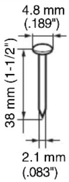 | 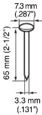 |  |  |
Dimensions of nails
STANDARD ACCESSORIES
(1) Eye protector ....1
(2) Oiler 1
(3) Nose cap ....1
APPLICATIONS
○ Construction wooden works such as floor and wall framing, roof decking and subfl ooring.
○ Mobile and modular home construction.
○ Making wooden boxes, palletes, and drums.
○ Packing operations in manufacturing plants, and other types of packing and crating work in general.
Use an air hose designed for high-pressure operation.
Be sure to use the hose provided with minimum 5 mm (13/64") inside diameter.
NOTE
The air supply hoses must have a minimum working pressure rating of 29.4 bar (420 psi).
2. Check on safety
CAUTION
- Unauthorized persons (including children) must be kept away from the equipment.
○ Wear eye protector.
○ Check the retaining screws which fix the exhaust cover, etc. for tightness.
Check the nailer for air leaks and defective or rusty parts.
☐ Check whether or not the push lever works correctly. Also check whether or not any dirt has adhered to the moving parts of the push lever.
○ Recheck on operational safety.
BEFORE USE
1. Check the air pressure
CAUTION
Use a compressor designed for high-pressure operation.
The air pressure must be constantly maintained at 12 – 23 bar (170 – 320 psi).
Adjust the air pressure between 12 to 23 bar (170 – 320 psi) according to the diameters and length of nails and hardness of the wood being nailed. Pay special attention to the output pressure, capacity, and piping on the air compressor, so that air pressure does not exceed the specified limit. Note that excessive pressure may affect overall performance, service life, and safety.
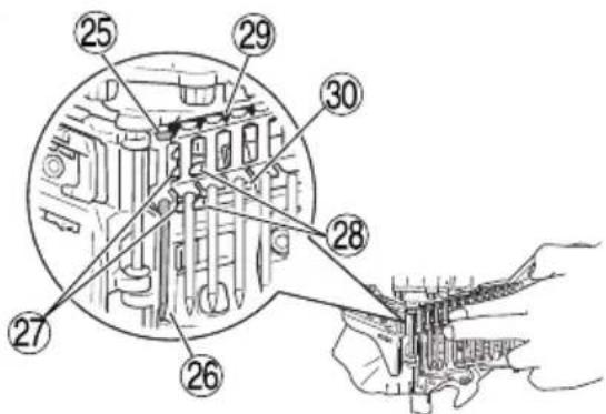
2. Lock mechanism of the trigger
This device has a lock mechanism to prevent the trigger from pulling.
Set the lock lever to "Lock" position to lock the trigger in place.
To drive a nail, turn the lock lever to the "Free" position. When not driving nails set the lever to the "Lock" position (Fig. 2).
CAUTION
Keep the trigger locked at all times except when driving nails.
3. Lubrication
(1) Be sure to lubricate this nailer at least twice a day. To lubricate, pour 10 to 15 drops of oil into the air plug before and after using this nailer. The oil applied before use lubricates this nailer; the oil applied after use prevents rust.
(2) It is recommended using the recommended oil (SHELL TONNA). Other applicable oils are listed. Never mix two or more types of different oils.
4. Nose Selection and Switching
This nailer allows you to switch the nail outlet between two sizes to extend the range of usable types and sizes of nails. Set the nose switch lever to select the outlet size matching the head diameter of the nail to be used as shown below (Fig. 3).
| Head Diameter | Outlet size |
| 4.8 mm – 6.0 mm(0.189" – 0.236") | Small |
| 6.0 mm – 7.3 mm(0.236" – 0.287") | Large |
CAUTION
Be sure to disconnect the air hose before operating the nose switch lever.
NOTE
Be sure to switch to the appropriate nose for the nails to be used. Selecting an inappropriate nose may cause defective nailing or sparking. It may also cause a nail jam, damage to this nailer or personal injury.
5. Load Nails
(1) Grip the nail guide and knob with finger.
Press the knob down and swing the nail guide open.
And open the magazine cover (Fig. 4).
(2) Adjust the position of the nail holder according to the nail length (Fig. 5).
The nail will not feed smoothly if the nail holder is not correctly adjusted (Fig. 6).
a. Turn the nail holder about 90 degrees counterclockwise.
b. Slide in vertical direction possible.
a. Turn the nail holder about 90 degrees counterclockwise. b. Slide in vertical direction possible.
Lift or lower the nail holder to accept different length nails.
c. Adjust the plate to the nail length reference points on the magazine cover and turn the nail holder 90 degrees clockwise until you hear "click".
(3) Place the nail coil into the magazine.
Uncoil enough nails to reach the driving hole (Fig. 7).
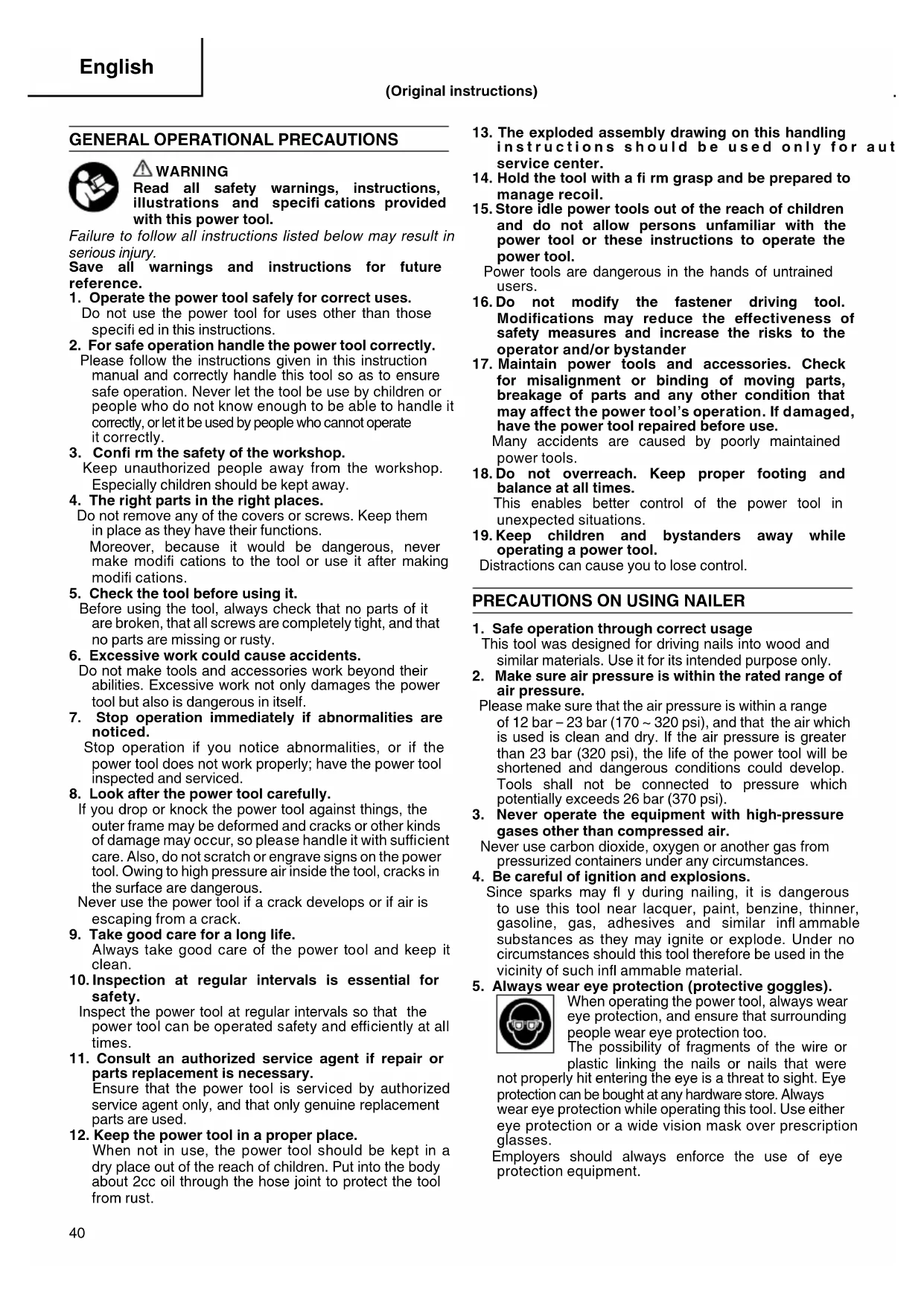
When using wire collated nails
Insert the first nail into the driving hole and the second nail between the two pawls of the feeder.
Fit the nail head in the guide slot (Fig. 8).
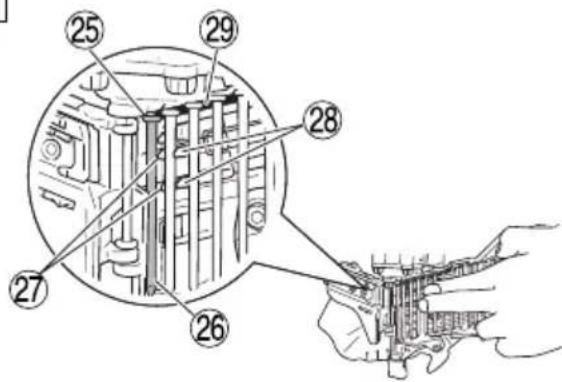
When using plastic sheet collated nails
Insert the first nail into the driving hole and the second nail between the two pawls of the feeder.
Fit the nail head and upper side of the plastic sheet in the guide slot.
Fit the lower side of the plastic sheet in the guide slot for plastic sheets (Fig. 9).
(4) Close the magazine cover first and swing the nail guide closed (Fig. 10).
(5) Lock the knob correctly.
NOTE
Be careful not to deform the collated wires and not to disengage the nails with the guide surface.
Otherwise, the nail guide will not close correctly.
CAUTION
To prevent unintentional operation, never touch the trigger or place the top end of the push lever on a work bench or floor. Also, never face the nail outlet toward any part of a person.
NOTE
Before loading the nails in the magazine, position the nail holder according to the length of the nail. If the nail holder position is not adjusted properly, nail feed may jam. If the cover is forcibly closed without adjusting the position of the nail holder, the nail holder may be damaged.
Do not use the body or any portion of the tool as a hammer as nails may be discharged unexpectedly or the tool may become damaged and serious injury could occur.
○ Take precautions to ensure the safety of persons in the vicinity during operation.
- Ensure tool is always safely engaged on the workpiece and cannot slip.
○ Never carry a pneumatic tool by its hose.
○ Never drag a pneumatic tool by its hose.
1. Set the lock lever to "Free" position
Turn the lock lever and align it with the "Free" position (Fig. 11).
2. How to drive nails
This product is a nailer using SINGLE SEQUENTIAL ACTUATION MECHANISM. If you pull the trigger first, nothing will happen even if you press the push lever up against an object.
Depress the nail outlet onto the desired point; then pull the trigger to drive a nail in a single shot (See Fig. 13). After nailing once, nailing will not be possible again until the trigger is released and pressed again.
You cannot drive a nail by first pulling on the trigger and then pressing the push lever against an object (continuous nailing).
WARNING
A nail will fire each time the trigger is depressed as long as the push lever remains depressed.
CAUTION
Exercise care when nailing corners of lumber. When continuous nailing corners of lumber, a nail may go astray or break through the corner.
NOTE
○ Precautions on no-load operation.
Sometimes nailing will continue after driving in all nails previously contained in the magazine.
This is termed “no-load operation”. Such operation may deteriorate the bumper, magazine, and nail feeder. To avoid no-load operation, occasionally confirm the amount of remaining nails. On the other hand, all nails should be removed after using this nailer.
○ After completing operation, put into the body about 2 cc oil through the hose joint to protect the tool from rust.
○ Under low temperature conditions, the machine sometimes does not operate correctly. Always operate the machine at the appropriate ambient temperature.
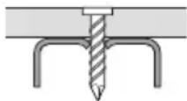
3. Driving nails into steel plating CAUTION
○ Use C-beam steel with a thickness of 2.3 mm or less.
○ Use hardened nails designed for use with steel plating.
○ Place the nailer vertically over the location into which the nail is to be driven.
○ Do not drive nails directly into C-beam steel or attach wire mesh laths, galvanized steel etc. directly onto it.
○ Do not use the nailer on roofs or ceilings.
○ Make sure that the thickness of the hardened nails designed for use with steel plating are of the correct thickness for the C-beam steel.
NOTE
Use the single shot setting to improve the finish after the nails have been driven in.
Refer to the following table to select the correct nail shaft diameter and length.
[Selecting Nail Shaft Diameter]
| C-Beam Steel Thickness | Nail Shaft Diameter |
| 2.3 mm or less | 2.8 mm |
[Selecting Nail Length]
| Material Thickness | Nail Length |
| 10 to 22 mm | 32 mm |
| 10 to 27 mm | 38 mm |
| 15 to 30 mm | 45 mm |
| 15 to 38 mm | 50 mm |

Material Thickness
Approximately 10 to 35 mm
C-beam Steel
(Thickness: 1.6 mm to a maximum of 2.3 mm)
NOTE
○ Holding power will be greatly decreased if nails are driven too hard into steel plating. Rotate the adjuster downwards to adjust the depth of the nails.
There are cases in which the nails will not be driven in sufficiently depending on a combination of the hardness and thickness of the C-beam or material.
The external material and steel plating is not deformed.
The external material and steel plating is deformed.
4. Driving nails into concrete CAUTION
○ Use hardened nails designed for use with concrete.
○ Place the nailer vertically over the location into which the nail is to be driven.
○ Do not drive nails directly into concrete or attach metal plates directly onto it.
○ Do not drive nails into the edge of concrete.
○ Do not use the nailer in locations from which other items are suspended (suspended pipes, etc.).
NOTE
○ Only use the nailer on concrete that has not yet set, soon after it has been poured.
Using the nailer on hardened concrete may result in bent nails and nails being insufficiently driven in.
○ Use the single shot setting to improve the finish after the nails have been driven in.
[Selecting hardened nails for use with concrete]
Select nails with a concrete intrusion depth of between 10 to 15 mm.
Reference Examples
| Wood Thickness | Length of Nails to be Used | Concrete Intrusion Depth |
| 20 mm 32 mm | Approx. 12 mm | |
| 25 mm 38 mm | Approx. 13 mm | |
| 30 mm 45 mm | Approx. 15 mm | |
| 35 mm 50 mm | Approx. 15 mm |

NOTE
The nails will not be driven in sufficiently if the concrete intrusion depth is deeper than 15 mm.
5. Adjusting the nail-driving depth CAUTION
When making adjustments, be sure remove your finger from the trigger. When making adjustme that the nail outlet is not facing downward and that body parts or other people are not in the path of the nail outlet.
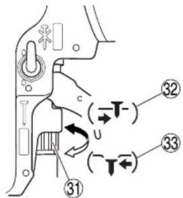
○ Adjusting the adjuster (Fig. 14)
Carry out test driving. If the nails are too deep, turn the adjuster to the shallow side ( mark). If the nail depth is too shallow, turn the adjuster to the deep side ( mark) (See Fig. 14, 15). Depth is changed 1 mm with each rotation of the adjuster.
NOTE
When adjusting the adjuster, it does not rotate more than 3 mm from the deepest point where a nail goes down. Do not rotate the adjuster by force beyond that point.
☐ The nail-driving depth can also be adjusted by changing the air pressure used. Carry this out together with movement of the adjuster. Using a high air pressure that does not match the nail-driving resistance will shorten the life of this nailer.
6. Changing the exhaust direction
The direction of the exhaust vent can be changed by turning the top cover (See Fig. 16).
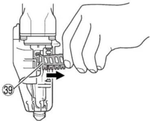
7. Cutting off the sheet
Tear off the output sheet in the direction of the arrow when using the sheet collated nails (Fig. 17).
8. Using the blow nozzle CAUTION
○ Be sure to release your finger from the trigger before using the blow nozzle.
○ Do not point the air outlet at a person.
○ Do not use the blow nozzle with the push lever left fit.
This Nailer has a blow nozzle that blows out wood shavings which occur during work.
Press the knob with your thumb to use the blow nozzle (See Fig. 18).
NOTE
When the blow nozzle is used for a long time, the nailing force may degrade temporarily. In this case, allows the air supply pressure to stabilize before starting work.
Oil in the body or drained water from the compressor can sometimes spout out of the air outlet. It is recommended that you once conduct a test before use and see if such phenomenon happens at an environment where spouted oil will cause any inconvenience.
9. How to use nosecap CAUTION
Remove the hose from the nailer and release the compressed air before installing or removing the nosecap to prevent accidental nail ejection.
○ Attach the nose cap on the tip of the push lever when you wish to protect the surface of wood, etc., from scratches.
(1) Attaching and detaching nose cap
The nose cap can be attached by simply pressing it into the push lever.
Press it in until a convex part inside the nose cap enters into a hole of the push lever. (Fig. 19)
For removal, insert a thin rod such as a screw driver into the gap on the back of the push lever, and then pull it out.
(2) Safekeeping of nose cap
Put the removed nose cap in a space behind the magazine for safekeeping. (Fig. 20)
INSPECTION AND MAINTENANCE
CAUTIONure
Be sure to disconnect the hose during cleaning jams, inspection, maintenance and cleaning.
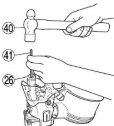
1. Countermeasure for nail jamming
(1) Remove the nail roll from the magazine, open the nail guide, insert a rod into the outlet and tap the rod with a hammer (Fig. 21).
(2) Remove the jammed nail with slotted screwdriver (Fig. 22).
(3) Cut off the defective part of the steel wire which links the nails with cutting nippers, correct the deformation, then load the nail roll in the magazine.
(4) In case of frequent jams, consult the Authorized Service Center from which you bought this machine.
2. Check on mounting screws for each part
At regular intervals check every part for loose mounting screws and whether or not there are any air leaks. Retighten any loose screws. Operating the equipment with loose screws untightened will incur a hazard.
3. Inspecting the push lever
Check if the push lever can slide smoothly (Fig. 23).
Clean up the sliding area of the push lever and use the provided oil for lubrication from time to time. Lubrication enables smooth sliding and simultaneously serves to prevent the formation of rust.
4. Inspecting the feeders
(1) Occasionally clean the knob sliding part and then apply the recommended oil (See Fig. 23).
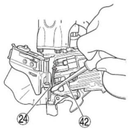
(2) Open the nail guide and remove dust, etc., as shown in Fig. 24. Apply lubricant to the sliding groove of the feeder and shaft. Check the nail stopper (A) and nail stopper (B) slide smoothly by pushing them with your finger.
(3) Also, apply the recommended oil to the feeding surface of the nose and nail guide after cleaning. This promotes smooth operation and retards corrosion.
CAUTION
Check for smooth movement of the feeders and stoppers before use. If movement is uneven, nails could be fired at an irregular angle, presenting a hazard to the operator and others nearby.
5. Inspect the Trigger
Periodically clean the sliding parts of the trigger, and make sure that the trigger moves smoothly (Fig. 25).
6. Inspecting the muffler
This Nailer has a built-in muffler in the exhaust to reduce noise and stirred-up dust during exhaust. When the mesh of the muffler is filled or the muffler is damaged, replace the muffler with a new one. To replace the muffler, contact our Authorized Service Center (Fig. 26).
7. Inspecting the magazine
Clean the magazine. Remove dust of wooden chips which may have accumulated in the magazine.
8. Storing
- When not in use for an extended period, apply a thin coat of the lubricant to the steel parts to avoid rust.
- Do not store the Nailer in a cold weather environment. Keep the Nailer in a warm area.
- When not in use, the Nailer should be stored in a warm and dry place.
Keep out of reach of children.
CAUTION
In the operation and maintenance of power tools, the safety regulations and standards prescribed in each country must be observed.
COMPRESSOR
CAUTION
When the maximum, operating pressure of the air compressor exceeds 23 bar (320 psi), be sure to provide a reducing valve between the air compressor and nailer. Then, adjust the air pressure within the operating range of 12 – 23 bar (170 – 320 psi). If the air set is installed, lubrication is also possible, thus providing additional convenience.
APPLICABLE LUBRICANTS
| Type of lubricant | Name of lubricant |
| Recommended oil | SHELL TONNA |
| Motor oil | SAE10W, SAE20W |
| Turbine oil | ISO VG32 - 68 (#90 - #180) |
Noise Information
Noise characteristic values in accordance with EN ISO 11148-13:2018
The typical A-weighted single-event sound power level L_WA,1s,d=95.0 dB
The typical A-weighted single-event emission sound pressure level at work station L_pA,1s,d=88.1 dB Uncertainty K: 2.5 dB (A)
These values are tool-related characteristic values and do not represent the noise development at the point of use. Noise development at the point of use will for example depend on the working environment, the workpiece, the workpiece support and the number of driving operations, etc.
Depending on the conditions at the workplace and the form of the workpiece, individual noise attenuation measures may need to be carried out, such as placing workpieces on sound-damping supports, preventing workpiece vibration by means of clamping or covering, adjusting to the minimum air pressure required for the operation involved, etc.
In special cases it is necessary to wear hearing protection equipment.
Vibration Information
The typical vibration characteristic value in accordance with EN ISO 11148-13:2018, 2000: 2.9 m/s ^2 Uncertainty K = 1.5 m/s ^2
This values is a tool-related characteristic value and does not represent the influence to the hand-arm-system when using the tool. An influence to the hand-arm-system when using the tool will for example depend on the gripping force, the contact pressure force, the working direction, the adjustment of energy supply, the workpiece, the workpiece support.
AVERTISSEMENTS GENERAUX

⚠ AVERTISSEMENT
INSPECTION ET MANUTENTION
ATTENTION
Kjeller Vest 7, N-2007 Kjeller, Norway
Tel: (+47) 6692 6600
Fax: (+47) 6692 6650
URL: http://www.hikoki-powertools.no
Hikoki Power Tools Sweden AB
Rotebergsvagen 2B SE-192 78 Sollentuna, Sweden
Tel: (+46) 8 598 999 00
Fax: (+46) 8 598 999 40
URL: http://www.hikoki-powertools.se
Hikoki Power Tools Denmark A/S
Lillebaeltsvej 90, 6715 Esbjerg N, Denmark
Tel: (+45) 75 14 32 00
Fax: (+45) 75 14 36 66
URL: http://www.hikoki-powertools.dk
Hikoki Power Tools Finland Oy
Tupalankatu 9, 15680 Lahti, Finland
Tel: (+358) 20 7431 530
Fax: (+358) 20 7431 531
URL: http://www.hikoki-powertools.fi
| Svenska Suomi | ||
| EG-DEKLARATION BETRÄFFANDE LIKFORMIGHETVi förklarar på eget ansvar att produkten högtrycksverktyg rullbandad, identifierad enligt typ och särskild identifikationskod *1), överensstämmer med alla relevanta krav i direktiven *2) och standarderna *3). Teknisk fi l enligt *4) – Se nedan.Den europeiska standardansvariga på representationskontoret i Europa är auktoriserad att sammanställa den tekniska fi len.Denna försäkran gäller för produkten med tillhörande CE-märkning. | EY-ILMOITUS YHDENMUKAISUUDESTAVakuutamme yksinomaisella vastuullamme, että korkeapainerullanaulain, joka identifioidaan tyypin ja erityisen tunnistuskoodin *1) perusteella, on kaikkien direktiivien *2) ja standardien *3) asiaankuuluvien vaatimusten mukainen. Tekninen tiedosto kohdassa *4) – katso alta.Eurooppalaisten standardien hallintaelin Euroopan edustustossa on valtuutettu kokoamaan teknisen tiedoston.Ilmoitus on sovellettavissa tuotteeseen kiinnitettyyn CE-merkintään. | |
| Dansk English | ||
| EF-OVERENSSTEMMELSESERKLÆRINGVi erklærer os fuldstændigt ansvarlige for, at Højtryks-sømpistolen, identificeret ved type og specifik identifikationskode *1), er i overensstemmelse med alle relevante krav i direktiverne *2) og standarderne *3). Teknisk fi l *4) – Se nedenfor.Lederen af europæiske standarder på repræsentationskontoret i Europa er bemyndiget til at kompilere den tekniske fi l.Erklæringen gælder produktet, der er mærket med CE. | EC DECLARATION OF CONFORMITYWe declare under our sole responsibility that High Pressure Coil Nailer, identified by type and specific identification code *1), is in conformity with all relevant requirements of the directives *2) and standards *3). Technical fi le at *4) – See below.The European Standard Manager at the representative office in Europe is authorized to compile the technical fi le.The declaration is applicable to the product affi xed CE marking. | |
| Norsk Français | ||
| EF'S ERKLÆRING OM OVERENSSTEMMELSEVi erklærer på eget ansvar at Rundmagasinert Høytrykksverktøy, identifisert etter type og spesifik identifikasjonskode *1), er i samsvar med alle relevante krav i direktiver *2) og standarder *3). Teknisk fil under *4) - Se nedenfor.Styreren for europeiske standarder ved representantkontoret i Europa er autorisert til å kompilere den tekniske fi len.Erklæringen gjelder for CE-merket på produktet. | DECLARATION DE CONFORMITE CENous déclarons sous notre entière responsabilité que le Cloueur rouleau à air comprimé, identifié par le type et le code d'identification spécifique *1) est en conformité avec toutes les exigences applicables des directives *2) et des normes *3). Dossier technique en *4) - Voir ci-dessous.Le Gestionnaire des normes européennes du bureau de représentation en Europe est autorisé à constituer le dossier technique.Cette déclaration s'applique aux produits désignés CE. | |
| *1) NV65HMC C339840B*2) 2006/42/EC*3) EN ISO 11148-13:2018 | ||
| *4) Representative offi ce in EuropeHikoki Power Tools Deutschland GmbHSiemensring 34, 47877 Willich, GermanyHead offi ce in JapanKoki Holdings Co., Ltd.Shinagawa Intercity Tower A, 15-1, Konan 2-chome, Minato-ku, Tokyo, Japan | 31. 10. 2019Naoto YamashiroEuropean Standard Manager31. 10. 2019A. NakagawaCorporate Offi cer | |
Koki Holdings Co., Ltd.

- ALLMÄNNA SÄKERHETSFÖRESKRIFTER FÖR ELVERKTYG
- WARNING
- Drive spiker inn i betong ADVARSEL
- INSPEKSJON OG VEDLIKEHOLD
- ADVARSEL
- PRECAUTIONS ON USING NAILER
- Protect your ears and head.
- Pay attention to those working close to you.
- Never point the nail outlet towards people.
- Before using the power tool, check the push lever.
- Use specifi ed nails only.
- Do not modify the fastener driving tool.
- Be careful when connecting the hose.
- Beware of the tool's kickback
- Simultaneous nailing on both sides of the same wall is dangerous
- Do not use the power tool on scaffoldings, ladders.
- Do not disconnect the hose with your finger on the trigger.
- Disconnect the hose and take out any nails left in the magazine after use.
- NAIL SELECTION
- STANDARD ACCESSORIES
- APPLICATIONS
- NOTE
- Check on safety
- CAUTION
- BEFORE USE
- Check the air pressure
- Lock mechanism of the trigger
- Lubrication
- Nose Selection and Switching
- Load Nails
- When using wire collated nails
- When using plastic sheet collated nails
- Set the lock lever to "Free" position
- How to drive nails
- Driving nails into steel plating CAUTION
- C-beam Steel
- Driving nails into concrete CAUTION
- Adjusting the nail-driving depth CAUTION
- Changing the exhaust direction
- Cutting off the sheet
- Using the blow nozzle CAUTION
- How to use nosecap CAUTION
- INSPECTION AND MAINTENANCE
- CAUTIONure
- Countermeasure for nail jamming
- Check on mounting screws for each part
- Inspecting the push lever
- Inspecting the feeders
- Inspect the Trigger
- Inspecting the muffler
- Inspecting the magazine
- Storing
- COMPRESSOR
- Noise Information
- Vibration Information
- AVERTISSEMENTS GENERAUX
- ⚠ AVERTISSEMENT
- INSPECTION ET MANUTENTION
- ATTENTION
- Hikoki Power Tools Sweden AB
- Hikoki Power Tools Denmark A/S
- Hikoki Power Tools Finland Oy
- Koki Holdings Co., Ltd.
Brand : HiKOKI
Model : NV65HMC
Category : Stapler