
CM12Y - Slicer HiKOKI - Free user manual and instructions
Find the device manual for free CM12Y HiKOKI in PDF.
| Brand | HiKOKI |
| Model | CM12Y |
| Product Type | Disc Cutter (Cut-off Saw) |
| Main Use | Cutting concrete, tile, stone, brick, and steel |
| Power Consumption | 2400 W |
| Power Supply Voltage | 110 V, 120 V, 127 V, 220 V, 230 V, 240 V depending on region |
| No Load Speed | 5000 min⁻¹ |
| Disc Outer Diameter | 305 mm |
| Disc Bore | 22.2 mm or 20 mm (depending on washer) |
| Maximum Cutting Depth | 100 mm |
| Net Weight (without cable or disc) | 11.5 kg |
| Motor | Carbon brush motor |
| Cable Length | Approx. 2 m (not specified, estimated) |
| Sound Pressure Level (LpA) | 102 dB(A), uncertainty K=3 dB(A) |
| Sound Power Level (LwA) | 113 dB(A), uncertainty K=3 dB(A) |
| Vibration (cutting concrete) | 4.6 m/s², uncertainty K=1.5 m/s² |
| Safety Protection | Adjustable safety guard, shaft lock, safety switch |
| Included Accessories | Dust collection hose, mounting wrench, safety glasses |
| Optional Accessories | Diamond blades (segment type), metal and masonry cutting discs, 25.4 mm washer |
| Maintenance | Regular check of carbon brushes, cleaning of ventilation slots, check of screws |
| Repairability | Spare parts available via HiKOKI authorized service center (brushes, discs, washers) |
| Warranty | Compliant with national regulations, excluding defects from abusive use |
| Standards | EN60745, ISO4871 |
| Country of Origin | Not specified (Japanese brand, possibly manufactured in China) |
Frequently Asked Questions - CM12Y HiKOKI
User questions about CM12Y HiKOKI
0 question about this device. Answer the ones you know or ask your own.
Ask a new question about this device
Download the instructions for your Slicer in PDF format for free! Find your manual CM12Y - HiKOKI and take your electronic device back in hand. On this page are published all the documents necessary for the use of your device. CM12Y by HiKOKI.
USER MANUAL CM12Y HiKOKI
Read through carefully and understand these instructions before use. Diese Anleitung vor Benutzung des Werkzeugs sorgfältig durchlesen und verstehen. Lire soigneusement et bien assimiler ces instructions avant usage. Prima dell'uso leggere attentamente e comprendere queste instruzioni. Deze gebruiksaanwijzing s.v.p. voor gebruik zorgvuldig doorlezen. Leer cuidadosamente y comprender estas instrucciones antes del uso.

Handling instructions Bedienungsanleitung Mode d'emploi Istruzioni per l'uso Gebruiksaanwijzing Instrucciones de manejo
1

2

3

4

5

6

7
8

| 17a | ||
| 18446mm | ||
| 1943Z7mm |
| English Deutsch Français | |||
| 1 | Dust collector hose Staubabscheiderschlauch Tuyau souple du collecteur de poussière | ||
| 2 | Hose Schlauch Tuyau souple | ||
| 3 | Wheel washer (B) Trennscheiben-Beilegscheibe (B) Rondelle de meule (B) | ||
| 4 | Wheel washer (C) Trennscheiben-Beilegscheibe (C) Rondelle de meule (C) | ||
| 5 | Spindle Spindel Arbre | ||
| 6 | Bolt Schraube Boulon | ||
| 7 | Diamond wheel Diamantschleifscheibe Disque rhomboïdal | ||
| 8 | Knob Knopf Bouton | ||
| 9 | Tighten Festziehen | Visser | |
| 10 | Loosen | Lösen Desserrer | |
| 11 | Lock pin | Verriegelungsstift | Tige de verrouillage |
| 12 | Wrench | Schlüssel Clé | |
| 13 | Pipe handle | Rohrhandgriff | Poignée de tuyau |
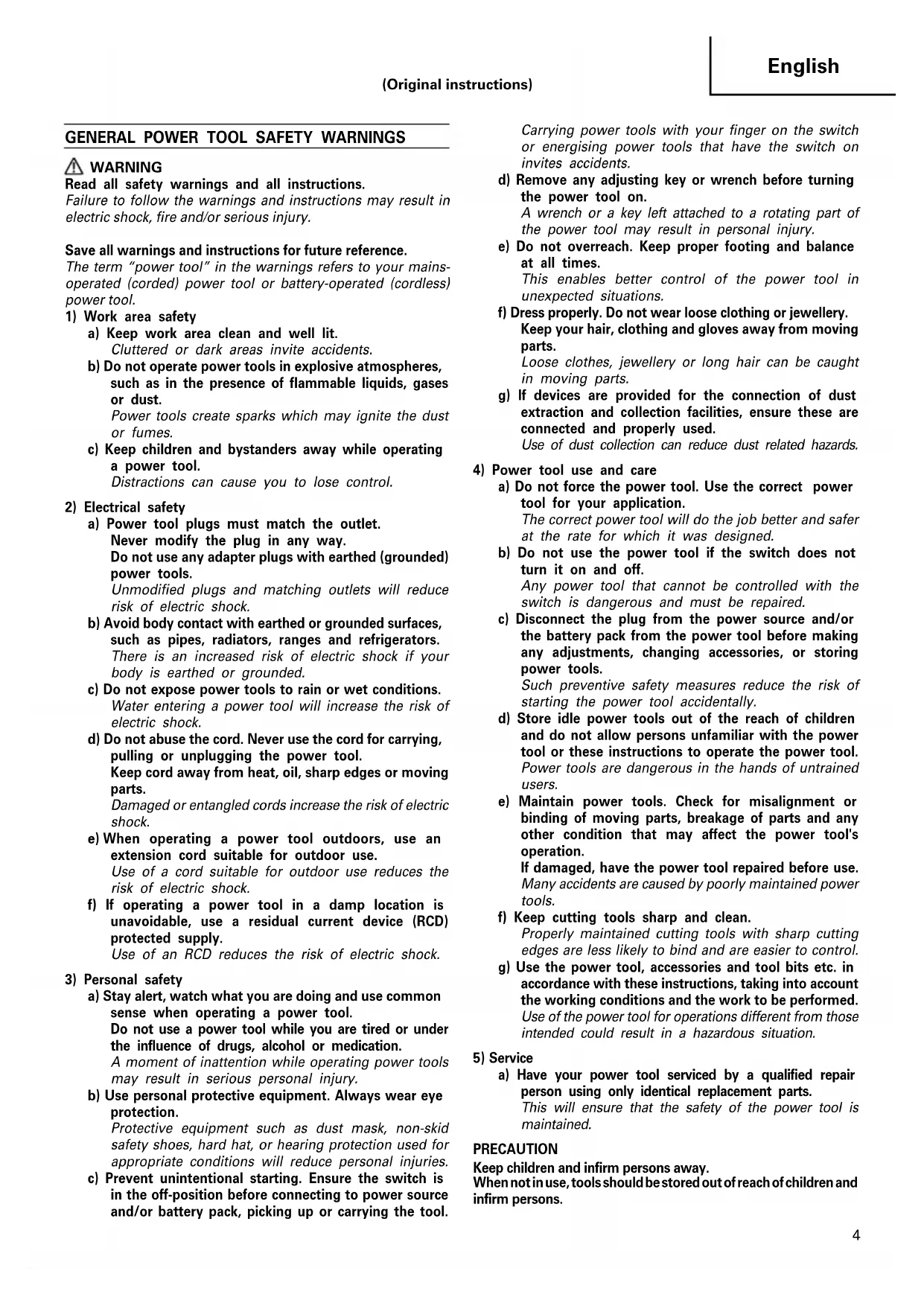
| 14 | Work piece | Werkstück | Pièce |
| 15 | Premarked line | Anrißlinie | Ligne de traçage |
| 16 | Wear limit | Verschleißgrenze | Limite d’usure |
| 17 | No. of carbon brush | Nr. der Kohlebürste | No. du balai en carbone |
| 18 | Usual carbon brush | Gewöhnliche Kohlebürste | Balai en carbone ordinaire |
| 19 | Auto-stop carbon brush | Auto-Stop Kohlebürste | Balai en carbone à arrêt automatique |
| Italiano | Nederlands | Español | |
| 1 | Tubo flessibile del collettore della polvere | Stofverzamelslang | Manguera del colector de polvo |
| 2 | Tubo flessibile | Slang | Manguera |
| 3 | Rondella per la mola (B) | Schijf sluitring (B) | Arandela de la muela (B) |
| 4 | Rondella per la mola (C) | Schijf sluitring (C) | Arandela de la muela (C) |
| 5 | Albero | As | Husillo |
| 6 | Bullone Bout | Perno | |
| 7 | Mola diamantata | Diamantschijf | Muela adiamantada |
| 8 | Pomèllo | Knop | Mando |
| 9 | Chiudere | Vastdraaien | Apretar |
| 10 | Allentare | Losdraaien | Aflojar |
| 11 | Spina di bloccaggio Vergrendelpen | Pasador de cierre | |
| 12 | Chiave | Sleutel | Llave |
| 13 | Impugnatura a tubo | Pijphendel | Asa del tubo |
| 14 | Pezzo da lavorare | Klus | Pieza de trabajo |
| 15 | Linea tracciata | Getekende streep | Línea trazada |
| 16 | Limite di usura | Slijtagegrens | Límite de desgaste |
| 17 | N. della spazzola di carbone | Nr. van de koolborstel | No. de la escobilla de carbón |
| 18 | Spazzola di carbonecomune | Normale koolborstel | Escobilla de carbón usual |
| 19 | Spazzola di carbone ad arresto automatico | Auto-stop koolborstel | Escobilla de carbón de parada automática |
| Symbols⚠ WARNINGThe following show symbols used for the machine. Be sure that you understand their meaning before use. | Symbole⚠ WARNUNGDie folgenden Symbole werden für diese Maschine verwendet. Achten Sie darauf, diese vor der Verwendung zu verstehen. | Symboles⚠ AVERTISSEMENTLes symboles suivants sont utilisés pour l’outil. Bien se familiariser avec leur signification avant d’utiliser l’outil. | |
 | Read all safety warnings and all instructions.Failure to follow the warnings and instructions may result in electric shock, fire and/or serious injury. | Lesen Sie sämtliche Sicherheitshinweise und Anweisungen durch.Wenn die Warnungen und Anweisungen nicht befolgt werden, kann es zu Stromschlag, Brand und/oder ernsthaften Verletzungen kommen. | Lire tous les avertissements de sécurité et toutes les instructions.Tout manquement à observer ces avertissements et instructions peut engendrer des chocs électriques, des incendies et/ou des blessures graves. |
 | Always wear eye protection. | Tragen Sie immer einen Augenschutz. | Toujours porter des verres de protection. |
 | Always wear hearing protection. | Stets Gehörschutz tragen. | Porter des protections anti-bruit en permanence. |
 | Only for EU countriesDo not dispose of electric tools together with household waste material!In observance of European Directive 2002/96/EC on waste electrical and electronic equipment and its implementation in accordance with national law, electric tools that have reached the end of their life must be collected separately and returned to an environmentally compatible recycling facility. | Nur für EU-LänderWerfen Sie Elektrowerkzeuge nicht in den Hausmüll!Gemäss Europäischer Richtlinie 2002/96/EG über Elektro- und Elektronik- Altgeräte und Umsetzung in nationales Recht müssen verbrauchteElektrowerkzeuge getrennt gesammelt und einer umweltgerechtenWiederververitung zugeführt werden. | Pour les pays européens uniquementNe pas jeter les appareils électriques dans les ordures ménagères!Conformément à la directive européenne 2002/96/EG relative aux déchets d’équipements électriques ou électroniques (DEEE), et à sa transposition dans la législation nationale, les appareils électriques doivent être collectés à part et être soumis à un recyclage respectueux de l’environnement. |
 | Simboli⚠ AVVERTENZADi seguito mostriamo i simboli usati per la macchina. Assicurarsi di comprenderne il significato prima dell’uso. | Symbolen⚠ WAARSCHUWINGHieronder staan symbolen afgebeeld die van toepassing zijn op deze machine. U moet de betekenis hiervan begrijpen voor gebruik. | Símbolos⚠ ADVERTENCIAÀ continuación se muestran los símbolos usados para la máquina. Asegúrese de comprender su significado antes del uso. |
 | Leggere tutti gli avvertimenti di sicurezza e tutte le istruzioni.La mancata osservanza degli avvertimenti e delle istruzioni potrebbe essere causa di scosse elettriche, incendi e/o gravi lesioni. | Lees alle waarschuwingen en instructies aandachtig door.Nalating om de waarschuwingen en instructies op te volgen kan in een elektrische schok, brand en/of ernstig letsel resulteren. | Lea todas las instrucciones y advertencias de seguridad.Si no se siguen las advertencias e instrucciones, podría producirse una descarga eléctrica, un incendio y/o daños graves. |
 | Indossate sempre le protezioni oculari. | Draag altijd oogbescherming. | Utilice siempre una protección ocular. |
 | Indossare sempre i dispositivi di protezione acustica. | Draag altijd gehoorbescherming. | Utilice siempre protecciones auriculares. |
 | Solo per Paesi UENon gettare le apparecchiature elettriche tra i rifiuti domestici.Secondo la Direttiva Europea 2002/96/CE sui rifiuti di apparecchiature elettriche ed elettroniche e la sua attuazione in conformità alle norme nazionali, le apparecchiature elettriche esauste devono essere raccolte separatamente, al fine di essere reimpiegate in modo eco-compatible. | Alleen voor EU-landenGeef elektrisch gereedschap niet met het huisvuil mee!Volgens de Europese richtlijn 2002/96/EG inzake oude elektrische en elektronische apparaten en de toepassing daarvan binnen de nationale wetgeving, dient gebruikt elektrisch gereedschap gescheiden te worden ingezameld en te worden afgevoerd naar een recycle bedrijf dat voldoet aan de geldende milieu-eisen. | Sólo para países de la Unión Europea¡No deseche los aparatos eléctricos junto con los residuos domésticos!De conformidad con la Directiva Europea 2002/96/CE sobre residuos de aparatos eléctricos y electrónicos y su aplicación de acuerdo con la legislación nacional, las herramientas eléctricas cuya vida útil haya llegado a su fin se deberán recoger por separado y trasladar a una planta de reciclaje que cumpla con las exigencias ecológicas. |
GENERAL POWER TOOL SAFETY WARNINGS
WARNING
Read all safety warnings and all instructions.
Failure to follow the warnings and instructions may result in electric shock, fire and/or serious injury.
Save all warnings and instructions for future reference.
The term "power tool" in the warnings refers to your mains-operated (corded) power tool or battery-operated (cordless) power tool.
1) Work area safety
a) Keep work area clean and well lit.
Cluttered or dark areas invite accidents.
b) Do not operate power tools in explosive atmospheres, such as in the presence of flammable liquids, gases or dust.
Power tools create sparks which may ignite the dust or fumes.
c) Keep children and bystanders away while operating a power tool.
Distractions can cause you to lose control.
2) Electrical safety
a) Power tool plugs must match the outlet.
Never modify the plug in any way.
Do not use any adapter plugs with earthed (grounded) power tools.
Unmodified plugs and matching outlets will reduce risk of electric shock.
b) Avoid body contact with earthed or grounded surfaces, such as pipes, radiators, ranges and refrigerators. There is an increased risk of electric shock if you body is earthed or grounded.
c) Do not expose power tools to rain or wet conditions. Water entering a power tool will increase the risk of electric shock.
d) Do not abuse the cord. Never use the cord for carrying, pulling or unplugging the power tool. Keep cord away from heat, oil, sharp edges or moving parts. Damaged or entangled cords increase the risk of electric shock.
e) When operating a power tool outdoors, use an extension cord suitable for outdoor use. Use of a cord suitable for outdoor use reduces the risk of electric shock.
f) If operating a power tool in a damp location is unavoidable, use a residual current device (RCD) protected supply.
Use of an RCD reduces the risk of electric shock.
3) Personal safety
a) Stay alert, watch what you are doing and use common sense when operating a power tool.
Do not use a power tool while you are tired or under the influence of drugs, alcohol or medication.
A moment of inattention while operating power tools may result in serious personal injury.
b) Use personal protective equipment. Always wear eye protection.
Protective equipment such as dust mask, non-skid safety shoes, hard hat, or hearing protection used for appropriate conditions will reduce personal injuries.
c) Prevent unintentional starting. Ensure the switch is in the off-position before connecting to power source and/or battery pack, picking up or carrying the tool.
Carrying power tools with your finger on the switch or energising power tools that have the switch on invites accidents.
d) Remove any adjusting key or wrench before turning the power tool on.
A wrench or a key left attached to a rotating part of the power tool may result in personal injury.
e) Do not overreach. Keep proper footing and balance at all times.
This enables better control of the power tool in unexpected situations.
f) Dress properly. Do not wear loose clothing or jewellery. Keep your hair, clothing and gloves away from moving parts.
Loose clothes, jewellery or long hair can be caught in moving parts.
g) If devices are provided for the connection of dust extraction and collection facilities, ensure these are connected and properly used.
Use of dust collection can reduce dust related hazards.
4) Power tool use and care
a) Do not force the power tool. Use the correct power tool for your application.
The correct power tool will do the job better and safer at the rate for which it was designed.
b) Do not use the power tool if the switch does not turn it on and off.
Any power tool that cannot be controlled with the switch is dangerous and must be repaired.
c) Disconnect the plug from the power source and/or the battery pack from the power tool before making any adjustments, changing accessories, or storing power tools.
Such preventive safety measures reduce the risk of starting the power tool accidentally.
d) Store idle power tools out of the reach of children and do not allow persons unfamiliar with the power tool or these instructions to operate the power tool. Power tools are dangerous in the hands of untrained users.
e) Maintain power tools. Check for misalignment or binding of moving parts, breakage of parts and any other condition that may affect the power tool's operation.
If damaged, have the power tool repaired before use. Many accidents are caused by poorly maintained power tools.
f) Keep cutting tools sharp and clean.
Properly maintained cutting tools with sharp cutting edges are less likely to bind and are easier to control.
g) Use the power tool, accessories and tool bits etc. in accordance with these instructions, taking into account the working conditions and the work to be performed. Use of the power tool for operations different from those intended could result in a hazardous situation.
5) Service
a) Have your power tool serviced by a qualified repair person using only identical replacement parts.
This will ensure that the safety of the power tool is maintained.
PRECAUTION
Keep children and infirm persons away.
When not in use, tools should be stored out of reach of children and infirm persons.
CUT-OFF MACHINE SAFETY WARNINGS
a) The guard provided with the tool must be securely attached to the power tool and positioned for maximum safety, so the least amount of wheel is exposed towards the operator. Position yourself and bystanders away from the plane of the rotating wheel.
The guard helps to protect operator from broken wheel fragments and accidental contact with wheel.
b) Use only bonded reinforced or diamond cut-off wheels for your power tool.
Just because an accessory can be attached to your power tool, it does not assure safe operation.
c) The rated speed of the accessory must be at least equal to the maximum speed marked on the power tool.
Accessories running faster than their rated speed can break and fly apart.
d) Wheels must be used only for recommended applications. For example: do not grind with the side of cut-off wheel.
Abrasive cut-off wheels are intended for peripheral grinding, side forces applied to these wheels may cause them to shatter.
e) Always use undamaged wheel flanges that are of correct diameter for your selected wheel.
Proper wheel flanges support the wheel thus reducing the possibility of wheel breakage.
f) Do not use worn down reinforced wheels from larger power tools. Wheels intended for a larger power tool are not suitable for the higher speed of a smaller tool and may burst.
g) The outside diameter and the thickness of your accessory must be within the capacity rating of your power tool.
Incorrectly sized accessories cannot be adequately guarded or controlled.
h) The arbour size of wheels and flanges must properly fit the spindle of the power tool.
Wheels and flanges with arbour holes that do not match the mounting hardware of the power tool will run out of balance, vibrate excessively and may cause loss of control.
i) Do not use damaged wheels. Before each use, inspect the wheels for chips and cracks. If power tool or wheel is dropped, inspect for damage or install an undamaged wheel. After inspecting and installing the wheel, position yourself and bystanders away from the plane of the rotating wheel and run the power tool at maximum no load speed for one minute.
Damaged wheels will normally break apart during this test time.
j) Wear personal protective equipment. Depending on application, use face shield, safety goggles or safety glasses. As appropriate, wear dust mask, hearing protectors, gloves and shop apron capable of stopping small abrasive or workpiece fragments.
The eye protection must be capable of stopping flying debris generated by various operations. The dust mask or respirator must be capable of filtrating particles generated by your operation. Prolonged exposure to high intensity noise may cause hearing loss.
k) Keep bystanders a safe distance away from work area. Anyone entering the work area must wear personal protective equipment.
Fragments of workpiece or of a broken wheel may fly away and cause injury beyond immediate area of operation.
I) Hold the power tool by insulated gripping surfaces only, when performing an operation where the cutting accessory may contact hidden wiring or its own cord.
Cutting accessory contacting a "live" wire may make exposed metal parts of the power tool "live" and could give the operator an electric shock.
m) Position the cord clear of the spinning accessory. If you lose control, the cord may be cut or snagged and your hand or arm may be pulled into the spinning wheel.
n) Never lay the power tool down until the accessory has come to a complete stop.
The spinning wheel may grab the surface and pull the power tool out of your control.
o) Do not run the power tool while carrying it at your side.
Accidental contact with the spinning accessory could snag your clothing, pulling the accessory into your body.
p) Regularly clean the power tool's air vents.
The motor's fan will draw the dust inside the housing and excessive accumulation of powdered metal may cause electrical hazards.
q) Do not operate the power tool near flammable materials.
Sparks could ignite these materials.
r) Do not use accessories that require liquid coolants.
Using water or other liquid coolants may result in electrocution or shock.
KICKBACK AND RELATED WARNINGS
Kickback is a sudden reaction to a pinched or snagged rotating wheel. Pinching or snagging causes rapid stalling of the rotating wheel which in turn causes the uncontrolled power tool to be forced in the direction opposite of the wheel's rotation at the point of the binding.
For example, if an abrasive wheel is snagged or pinched by the workpiece, the edge of the wheel that is entering into the pinch point can dig into the surface of the material causing the wheel to climb out or kick out. The wheel may either jump toward or away from the operator, depending on direction of the wheel's movement at the point of pinching. Abrasive wheels may also break under these conditions.
Kickback is the result of power tool misuse and/or incorrect operating procedures or conditions and can be avoided by taking proper precautions as given below.
a) Maintain a firm grip on the power tool and position your body and arm to allow you to resist kickback forces. Always use auxiliary handle, if provided, for maximum control over kickback or torque reaction during start-up.
The operator can control torque reactions or kickback forces, if proper precautions are taken.
b) Never place your hand near the rotating accessory. Accessory may kickback over your hand.
c) Do not position your body in line with the rotating wheel.
Kickback will propel the tool in direction opposite to the wheel's movement at the point of snagging.
d) Use special care when working corners, sharp edges etc. Avoid bouncing and snagging the accessory.
Corners, sharp edges or bouncing have a tendency to snag the rotating accessory and cause loss of control or kickback.
e) Do not attach a saw chain, woodcarving blade, segmented diamond wheel with a peripheral gap greater than 10 mm or toothed saw blade.
Such blades create frequent kickback and loss of control.
f) Do not "jam" the wheel or apply excessive pressure. Do not attempt to make an excessive depth of cut.
Overstressing the wheel increases the loading and susceptibility to twisting or binding of the wheel in the cut and the possibility of kickback or wheel breakage.
g) When wheel is binding or when interrupting a cut for any reason, switch off the power tool and hold the power tool motionless until the wheel comes to a complete stop. Never attempt to remove the wheel from the cut while the wheel is in motion otherwise kickback may occur.
Investigate and take corrective action to eliminate the cause of wheel binding.
h) Do not restart the cutting operation in the workpiece. Let the wheel reach full speed and carefully re-enter the cut.
The wheel may bind, walk up or kickback if the power tool is restarted in the workpiece.
i) Support panels or any oversized workpiece to minimize the risk of wheel pinching and kickback.
Large workpieces tend to sag under their own weight. Supports must be placed under the workpiece near the line of cut and near the edge of the workpiece on both sides of the wheel.
j) Use extra caution when making a "pocket cut" into existing walls or other blind areas.
The protruding wheel may cut gas or water pipes, electrical wiring or objects that can cause kickback.
PRECAUTION ON USING DISC CUTTER
- Never attach any tool except the diamond wheel or cutting wheel as specified by the manufacturer (see optional accessories).
Do not operate the cutter while applying water.
-
Always check the diamond wheel before starting the machine. If it is cracked, broken or bent, do not use it. Carefully start the machine to check for other abnormalities.
-
Using the diamond wheel to cut metal will shorten its service life or will result in breakage. Never use the diamond wheel to cut metal.
-
Start working only when maximum rotation speed is reached.
-
Excessive force overloads the motor and reduces working efficiency and service life. Always cut concrete, tile or stone with a cutting depth of 50mm or less. If the cutting depth is more than 50mm, cut the workpiece 2 or 3 times. If the workpiece is cut with a cutting depth of more than 50mm, the service life of the diamond wheel will be reduced and the motor may seize.
-
Do not use this machine to cut asbestos.
-
In operations using a cutting wheel, if flame comes out, cover the dust collection adapter with a rubber cap and be sure to wear protective glasses.
SPECIFICATIONS
| Voltage (by areas)* (110 V, 120 V, 127 V, 220 V, 230 V, 240 V) ~ | |
| Power input* 2400 W | |
| No-load speed 5000 min | -1 |
| Dimensions of diamond wheel | Outer dia. 305 mmThickness 2.0 mmHole dia. 22.2 mm / 20 mm |
| Max. cutting depth 100 mm | |
| Weight (without cord and diamond wheel) 11.5 kg | |
*Be sure to check the nameplate on product as it is subject to change by areas.
STANDARD ACCESSORIES
(1) Hose 1
(2) Wrench 1
(3) Protective glasses 1
Standard accessories are subject to change without notice.
OPTIONAL ACCESSORIES (sold separately)
(1) Diamond wheels for dry cutting (segment type)
| Type Wheel dia. (mm) | Code No. Thickness | (mm) Hole dia. (mm) | |
| For concrete and masonry | 305 | 985618 2.8 | 22.2 |
| For abrasive materials 985619 3.0 |
(2) Cutting wheels
| Type Wheel dia. (mm) | Code No. Hole dia. | (mm) per pkg. | ||
| Metal cutting wheel 985609 22.2 | 305 | 10 pcs. | ||
| 985608 25.4 | ||||
| Masonry cutting wheel 985611 22.2 | ||||
| 985610 25.4 |
(3) Wheel washer (A) (hole diameter 25.4mm)
Optional accessories are subject to change without notice.
APPLICATION
○Cutting or scribing concrete
○Cutting or scribing tile
○Cutting or scribing stone
○Cutting or scribing roof tile
○Cutting steel
PRIOR TO OPERATION
1. Power source
Ensure that the power source to be utilized conforms to the power requirements specified on the product nameplate.
2. Power switch
Ensure that the power switch is in the OFF position. If the plug is connected to a power receptacle while the power switch is in the ON position, the power tool will start operating immediately, which could cause a serious accident.
3. Extension cord
When the work area is removed from the power source, use an extension cord of sufficient thickness and rated capacity. The extension cord should be kept as short as practicable.
4. Checking and installing the diamond wheel
Check the diamond wheel is a specified one and is not cracked, broken or bent. Check the diamond wheel is installed securely. For installation, refer to "Installing/removing diamond wheel".
5. Check that the knob used to secure the wheel guard is tight.
Make sure that the knob that secures the wheel guard is adequately tight.
If this knob is loose, it may result in injury to the operator. (Fig. 4)
INSTALLING DUST COLLECTION HOSE
When cutting a material which generates cutting dust, use the dust collection hose as follows:
(1) Remove the rubber cap and install the accessory hose. (Fig. 1)
(2) Install the dust collector hose for the power tool in the accessory hose. (Fig. 1)
CAUTION
○Do not use the dust collection hose when cutting metal.
○Always install a rubber cap on the dust collection adapter when the dust collection hose is not used.
INSTALLING/REMOVING DIAMOND WHEEL
1. Installation
(1) Wipe the cutting dust from the spindle and washers. (2) Make sure the rotation direction of the diamond wheel conforms to the direction indicated on the wheel guard and install the diamond wheel as shown in Fig. 2 and 3.
- Install the wheel washer (B) (silver) on the inner side when the hole diameter of the diamond wheel is 22.2 mm.
- Install the wheel washer (C) (black) on the inner side when the hole diameter of the diamond wheel is 20.0 mm.
(3) Press the lock pin and secure the spindle. Tighten the bolt adequately with the provided wrench. (Fig. 5 and 6)
NOTE
○Always use the provided wrench to secure the bolt. ○Be careful because the bolt tightens to the left (counterclockwise direction) to prevent it from being loosened during cutting. (Fig. 6)
2. Removal
Remove the bolt with the provided wrench and remove the diamond wheel. (Fig. 6)
CUTTING
1. Wheel guard adjustment (Fig. 4)
Adjust the wheel guard angle with the knob so dust and debris from the material or sparks do not contact the operator during the cutting operation.
2. Cutting procedures (Fig. 7)
(1) Place this tool on the material to be cut and align the premarked line and the diamond wheel. The cutting can be performed smoothly if you cut straight ahead on the scribed line in the initial cut.
(2) Turn on the switch when the diamond wheel is not touching the material to be cut.
CAUTION
○Always check the diamond wheel before starting work. Never use a diamond wheel which is cracked, broken or bent.
○Do not apply water or coolant to the diamond wheel.
○Start cutting only when diamond wheel reaches its maximum speed.
○Switching the tool on and off repeatedly within a short time may cause burn damage of the motor.
○If the diamond wheel seizes or there is any abnormal noise, immediately turn the power off.
Never use the diamond wheel to cut zigzag or curved lines. Never use the side surface of the diamond wheel. Never use to perform inclination cutting.
○If excessive force is applied to the diamond wheel to make it align with the premarked line during cutting, this might not only overload the motor and cause burn damage but may also overheat the diamond wheel and shorten the service life.
- Secure the workpiece. A workpiece clamped with clamping devices or in a vice is held more securely than by hand.
○Take care not to allow the power cord to come into contact with the diamond wheel during operation.
When the work is completed, turn the power off and disconnect the power plug from the receptacle.
MAINTENANCE AND INSPECTION
1. Inspection the diamond wheel
A worn diamond wheel overloads the motor and reduces working efficiency. Replace with a new one.
2. Diamond wheel clogging
The rate of wear of the diamond layer cutting edge will vary depending on the type of material being cut, the cutting speed, etc. In general, materials which produce granular cutting particles may scrape the bodying agent and hasten the wear of the diamond layer. On the other hand, materials which produce powdery cutting particles may cause clogging of the diamond layer which will reduce cutting efficiency. When clogging occurs, additional force applied in an attempt to increase cutting speed will sometime cause sparks to appear around the circumference of the diamond wheel. In such a case, stop using the cutter and carefully inspect the cutting edge by rubbing it with your fingers. If the diamond layer feels smooth (no roughness or abrasiveness), it is clogged with dust and must be "dressed".
For thorough dressing, approximately 5 meters of slightly accelerated cutting at a depth of 10mm in a relative soft material which produces granular cutting particles (such as a cement block or brick) will restore the cutting effectiveness of the diamond layer and will extend the service life of the diamond wheel. The diamond material is susceptible to high temperatures and will begin to deteriorate at approximately 600°C. Higher temperatures will cause decomposition of the diamond material. Accordingly, it is important to perform “dressing” as soon as clogging or sparking occurs.
3. Inspecting the mounting screws
Regularly inspect all mounting screws and ensure that they are properly tightened. Should any of the screws be loose, retighten them immediately. Failure to do so could result in serious hazard.
4. Maintenance of the motor
The motor unit winding is the very "heart" of the power tool.
Exercise due care to ensure the winding does not become damaged and/or wet with oil or water.
5. Inspecting the carbon brushes (Fig. 8)
The motor employs carbon brushes which are consumable parts. Since an excessively worn carbon brush can result in motor trouble, replace the carbon brush with a new one having the same carbon brush numbers shown in the figure when it becomes worn to or near the "wear limit". In addition, always keep carbon brushes clean and ensure that they slide freely within the brush holders.
6. Replacing a carbon brush
Disassemble the brush cap with a minus-head screwdriver. The carbon brush can then be easily removed.
7. Service parts list
A: Item No.
B: Code No.
C: No. Used
D: Remarks
CAUTION
Repair, modification and inspection of HiKOKI Power Tools must be carried out by a HiKOKI Authorized Service Center.
This Parts List will be helpful if presented with the tool to the HiKOKI Authorized Service Center when requesting repair or other maintenance.
In the operation and maintenance of power tools, the safety regulations and standards prescribed in each country must be observed.
MODIFICATIONS
HiKOKI Power Tools are constantly being improved and modified to incorporate the latest technological advancements.
Accordingly, some parts (i.e. code numbers and/or design) may be changed without prior notice.
GUARANTEE
We guarantee HiKOKI Power Tools in accordance with statutory/country specific regulation. This guarantee does not cover defects or damage due to misuse, abuse, or normal wear and tear. In case of complaint, please send the Power Tool, undismantled, with the GUARANTEE CERTIFICATE found at the end of this Handling instruction, to a HiKOKI Authorized Service Center.
NOTE
Due to HiKOKI's continuing program of research and development, the specifications herein are subject to change without prior notice.
IMPORTANT
Correct connection of the plug
The wires of the mains lead are coloured in accordance with the following code:
Blue: -Neutral
Brown: -Live
As the colours of the wires in the mains lead of this tool may not correspond with the coloured markings identifying the terminals in your plug proceed as follows: The wire coloured blue must be connected to the terminal marked with the letter N or coloured black. The wire coloured brown must be connected to the terminal marked with the letter L or coloured red. Neither core must be connected to the earth terminal. NOTE
This requirement is provided according to BRITISH STANDARD 2769: 1984.
Therefore, the letter code and colour code may not be applicable to other markets except the United Kingdom.
Information concerning airborne noise and vibration
The measured values were determined according to EN60745 and declared in accordance with ISO 4871.
The typical A-weighted sound pressure level: 102 dB (A) The typical A-weighted sound power level: 113 dB (A) Uncertainty KpA: 3 dB (A).
Wear hearing protection.
Vibration total values (triax vector sum) determined according to EN60745.
Cutting concrete slab:
Vibration emission value ah=4.6\ m/s2
Uncertainty K = 1.5 m/s²
The declared vibration total value has been measured in accordance with a standard test method and may be used for comparing one tool with another.
It may also be used in a preliminary assessment of exposure.
WARNING
○The vibration emission during actual use of the power tool can differ from the declared total value depending on the ways in which the tool is used.
○Identify safety measures to protect the operator that are based on an estimation of exposure in the actual conditions of use (taking account of all parts of the operating cycle such as the times when the tool is switched off and when it is running idle in addition to the trigger time).
VEILIGHEIDSWAARSCHUWINGEN VOOR DE AFKORTMACHINE
Siemensring 34, 47877 willich, Germany
Tel: +49 2154 49930
Fax: +49 2154 499350
URL: http://www.hikoki-powertools.de
Hikoki Power Tools Netherlands B.V.
Brabanthaven 11, 3433 PJ Nieuwegein, The Netherlands
Tel: +31 30 6084040
Fax: +31 30 6067266
URL: http://www.hikoki-powertools.nl
Hikoki Power Tools (U.K.) Ltd.
Precedent Drive, Rooksley, Milton Keynes, MK 13, 8PJ,
United Kingdom
Tel: +44 1908 660663
Fax: +44 1908 606642
URL: http://www.hikoki-powertools.uk
Hikoki Power Tools France S.A.S.
Hikoki Power Tools Belgium N.V./S.A.
Koningin Astridlaan 51, B-1780 Wemmel, Belgium
Tel: +32 2 460 1720
Fax: +32 2 460 2542
URL http://www.hikoki-powertools.be
Hikoki Power Tools Italia S.p.A
Via Piave 35, 36077, Altavilla Vicentina (VI), Italy
Tel: +39 0444 548111
Fax: +39 0444 548110
URL: http://www.hikoki-powertools.it
Hikoki Power Tools Ibérica, S.A.
C/ Puigbarral, 26-28, Pol. Ind. Can Petit, 08227 Terrassa
(Barcelona), Spain
Tel: +34 93 735 6722
Fax: +34 93 735 7442
URL: http://www.hikoki-powertools.es
| English Italia ho | ||
| EC DECLARATION OF CONFORMITYWe declare under our sole responsibility that Disc Cutter, identified by type and specific identification code *1), is in conformity with all relevant requirements of the directives *2) and standards *3). Technical fi le at *4) - See below.The European Standard Manager at the representative office in Europe is authorized to compile the technical fi le.The declaration is applicable to the product affi xed CE marking. | DICHIARAZIONE DI CONFORMITÀ CEDichiariamo sotto la nostra esclusiva responsabilità che lo Scanalatore, identificato dal tipo e dal codice identificativo specifico *1), è conforme a tutti i requisiti delle direttive *2) e degli standard *3). Documentazione tecnica presso *4) - Vedere sotto.Il gestore delle norme europee presso l'ufficio di rappresentanza in Europa è autorizzato a compilare il fascicolo tecnico.La dichiarazione è applicabile ai prodotti cui sono applicati i marchi CE. | |
| Deutsch Nederlands | ||
| EG-KONFORMITÄTSERKLÄRUNGWir erklären in alleiniger Verantwortung, dass der durch den Typ und den spezifischen Identifizierungscode *1) identifizierte Trennschleifer allen einschlägigen Bestimmungen der Richtlinien *2) und Normen *3) entspricht. Technische Unterlagen unter *4) - Siehe unten.Die Leitung der repräsentativen Behörde für europäische Normen und Richtlinien ist berechtigt, die technischen Unterlagen zusammenzustellen.Die Erklärung gilt für die an dem Produkt angebrachte CE-Kennzeichnung. | EC VERKLARING VAN CONFORMITEITWij verklaren onder onze eigen verantwoordelijkheid dat Doorslijpmachine, geïdentificeerd door het type en de specifieke identificatiecode *1), voldoet aan alle relevante bepalingen van de richtlijnen *2) en normen *3). Technische documentatie bij*4) - zie onder.De Europese Normen Manager bij de vertegenwoordiging in Europa is gemachtigd om het technisch dossier samen te stellen.Deze verklaring is van toepassing op producten voorzien van de CE-markeringen. | |
| Français Español | ||
| DECLARATION DE CONFORMITE CENous déclarons sous notre entière responsabilité que la Tronçonneuse à disques, identifiée par le type et le code d'identification spécifique *1) est en conformité avec toutes les exigences applicables des directives *2) et des normes *3). Dossier technique en *4) - Voir ci-dessous.Le Gestionnaire des normes européennes du bureau de représentation en Europe est autorisé à constituer le dossier technique.Cette déclaration s'applique aux produits désignés CE. | DECLARACIÓN DE CONFORMIDAD DE LA CEDeclaramos bajo nuestra única responsabilidad que la Tronzadora, identificada por tipo y por código de identificación específico *1), está en conformidad con todas las disposiciones correspondientes de las directivas *2) y de las normas *3). Documentación técnica en *4) - Ver a continuación.El Director de Normas Europeas en la oficina de representación en Europa está autorizado para elaborar el expediente técnico.La declaración se aplica al producto con marcas de la CE. | |
| *1) CM12Y C331750R C331751M*2) 2006/42/EC, 2014/30/EU, 2011/65/EU*3) EN60745-1:2009+A11:2010EN60745-2-22:2011+A11:2013EN55014-1:2006+A1:2009+A2:2011EN55014-2:1997+A1:2001+A2:2008EN61000-3-2:2014EN61000-3-3:2013 | ||
| *4) Representative offi ce in EuropeHikoki Power Tools Deutschland GmbHSiemensring 34, 47877 Willich, GermanyHead offi ce in JapanKoki Holdings Co., Ltd.Shinagawa Intercity Tower A, 15-1, Konan 2-chome, Minato-ku, Tokyo, Japan | 29. 6. 2018Naoto YamashiroEuropean Standard Manager29. 6. 2018A. NakagawaCorporate Offi cer | |

- GENERAL POWER TOOL SAFETY WARNINGS
- WARNING
- CUT-OFF MACHINE SAFETY WARNINGS
- KICKBACK AND RELATED WARNINGS
- PRECAUTION ON USING DISC CUTTER
- STANDARD ACCESSORIES
- WHEEL WASHER (A) (HOLE DIAMETER 25.4MM)
- APPLICATION
- PRIOR TO OPERATION
- POWER SOURCE
- POWER SWITCH
- EXTENSION CORD
- CHECKING AND INSTALLING THE DIAMOND WHEEL
- CHECK THAT THE KNOB USED TO SECURE THE WHEEL GUARD IS TIGHT
- INSTALLING DUST COLLECTION HOSE
- CAUTION
- INSTALLING/REMOVING DIAMOND WHEEL
- INSTALLATION
- NOTE
- REMOVAL
- CUTTING
- WHEEL GUARD ADJUSTMENT (FIG. 4)
- CUTTING PROCEDURES (FIG. 7)
- MAINTENANCE AND INSPECTION
- INSPECTION THE DIAMOND WHEEL
- DIAMOND WHEEL CLOGGING
- INSPECTING THE MOUNTING SCREWS
- MAINTENANCE OF THE MOTOR
- INSPECTING THE CARBON BRUSHES (FIG. 8)
- REPLACING A CARBON BRUSH
- SERVICE PARTS LIST
- MODIFICATIONS
- GUARANTEE
- IMPORTANT
- CORRECT CONNECTION OF THE PLUG
- INFORMATION CONCERNING AIRBORNE NOISE AND VIBRATION
- VEILIGHEIDSWAARSCHUWINGEN VOOR DE AFKORTMACHINE
- HIKOKI POWER TOOLS NETHERLANDS B.V
- HIKOKI POWER TOOLS (U.K.) LTD
- HIKOKI POWER TOOLS FRANCE S.A.S
- HIKOKI POWER TOOLS BELGIUM N.V./S.A
- HIKOKI POWER TOOLS ITALIA S.P.A
- HIKOKI POWER TOOLS IBÉRICA, S.A
Brand : HiKOKI
Model : CM12Y
Category : Slicer