
H41SA - Hammer HiKOKI - Free user manual and instructions
Find the device manual for free H41SA HiKOKI in PDF.

| Product Type | Demolition Hammer |
| Brand | HiKOKI |
| Model | H41SA |
| Supply Voltage | 110-240 V depending on region (check the rating plate) |
| Power Consumption | 810 W |
| Full-load impact rate | 3000 min⁻¹ |
| Weight (without cord and side handle) | 4.8 kg |
| Included Accessories | Grinding point, side handle, storage case |
| Applications | Concrete grinding, chiseling, grooving, bar cutting, pile driving |
| Safety - Hearing protection | Use ear plugs recommended |
| Safety - Auxiliary handle | Provided and mandatory for control |
| Safety - Tool heating | Do not touch the bit after use, risk of burns |
| Safety - Wall check | Before drilling, ensure no cables or pipes |
| Maintenance - Grease replacement | Every 6 months or when replacing brushes (HiKOKI A grease) |
| Maintenance - Carbon brushes | Check regularly; replace with identical brushes if worn |
| Repairability | Take to an authorized HiKOKI service center |
| Warranty | According to national regulations, certificate provided |
| Standards and conformity | Conforms to EN60745, EEC directives 76/889 and 82/499 |
Frequently Asked Questions - H41SA HiKOKI
User questions about H41SA HiKOKI
0 question about this device. Answer the ones you know or ask your own.
Ask a new question about this device
Download the instructions for your Hammer in PDF format for free! Find your manual H41SA - HiKOKI and take your electronic device back in hand. On this page are published all the documents necessary for the use of your device. H41SA by HiKOKI.
USER MANUAL H41SA HiKOKI
Demolition Hammer Hammer Marteau de demolition Demolitore Hakhamer Martillo
H 41SA
natural_image
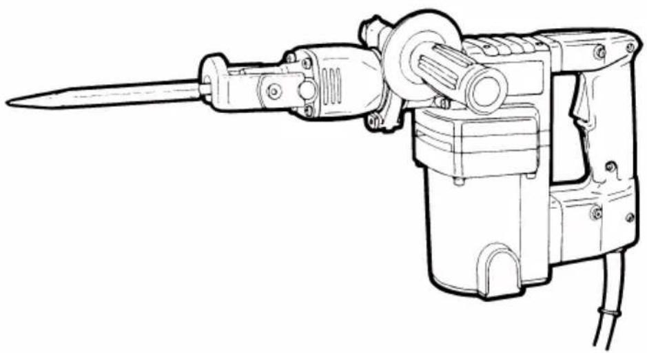
Line drawing of a mechanical tool with a pointed tip and attached housing (no text or symbols)Read through carefully and understand these instructions before use. Diese Anleitung vor Benutzung des Werkzeugs sorgfältig durchlesen und verstehen. Lire soigneusement et bien assimiler ces instructions avant usage. Prima dell'uso leggere attentamente e comprendere queste instruzioni. Deze gebruiksaanwijzing s.v.p. voor gebruik zorgvuldig doorlezen. Leer cuidadosamente y comprender estas instrucciones antes del uso.

Handling instructions Bedienungsanleitung Mode d'emploi Instruzioni per l'uso Gebruiksaanwijzing Instrucciones de manejo
text_image
1 ① ② ③ ④ A ⑤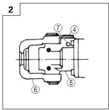
text_image
2 ⑦ ④ ⑤ ⑥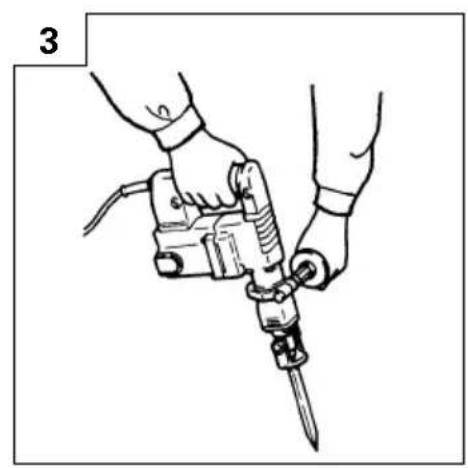
natural_image
Illustration of a hand using a power tool to tighten a screwdriver (no text or symbols present)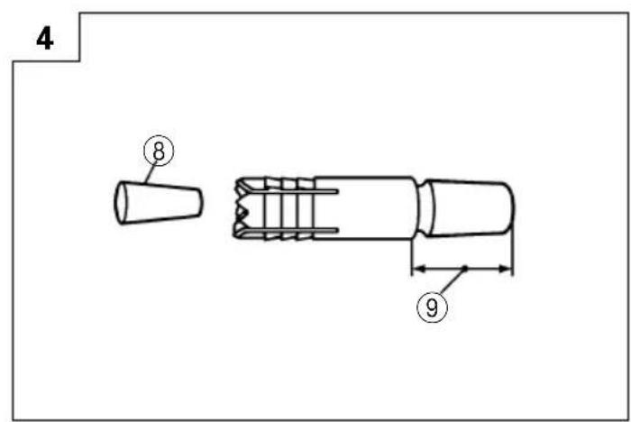
text_image
4 ⑧ ⑨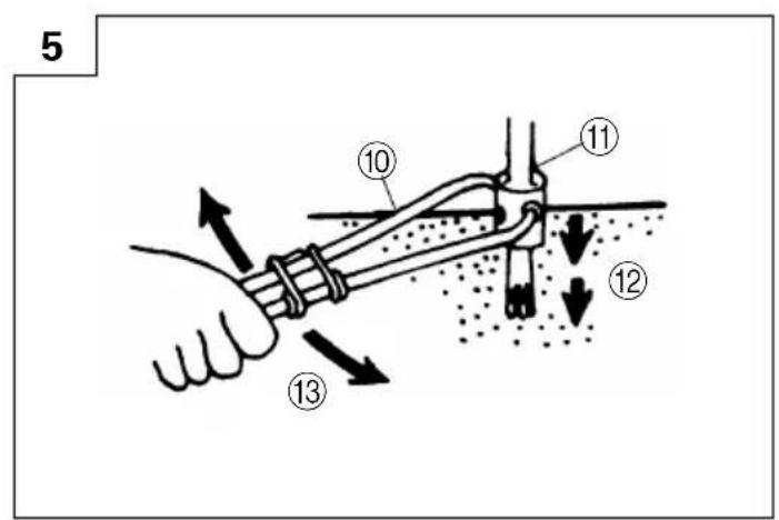
text_image
5 10 11 12 13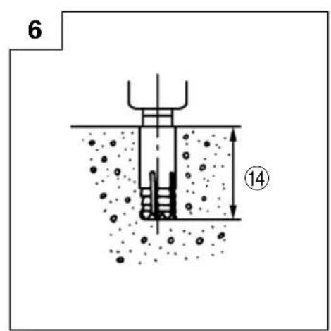
text_image
6 ⑭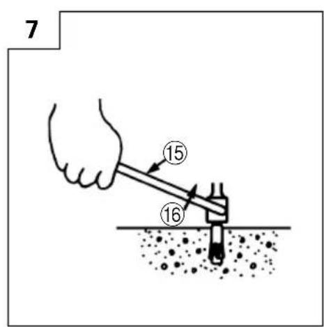
text_image
7 15 16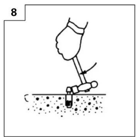
natural_image
Illustration of a hand using a tool to dig or press over soil (no text or symbols)
natural_image
Line drawing of a mechanical tool with labeled parts (9 and 17), no text or symbols present.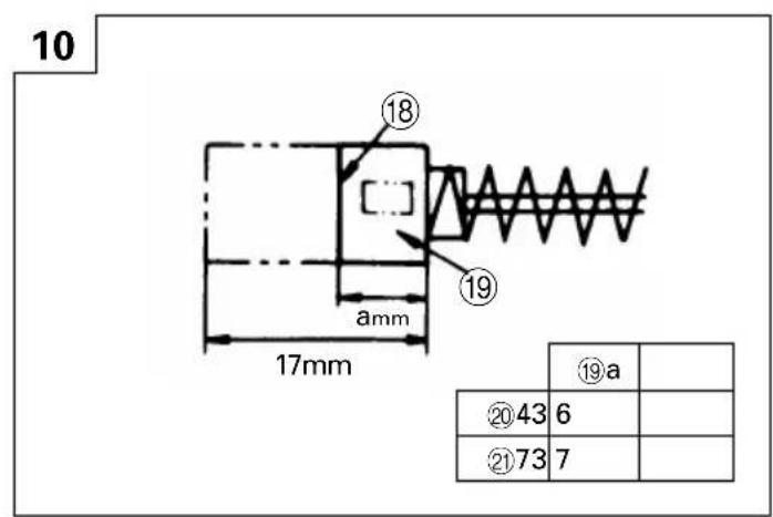
text_image
10 17mm ⑱ ⑲ ⑳a ⑳43 6 ⑳73 7Read all safety warnings and all instructions.
Failure to follow the warnings and instructions may result in electric shock, fire and/or serious injury.
Save all warnings and instructions for future reference.
The term "power tool" in the warnings refers to your mains-operated (corded) power tool or battery-operated (cordless) power tool.
1) Work area safety
a) Keep work area clean and well lit.
Cluttered or dark areas invite accidents.
b) Do not operate power tools in explosive atmospheres, such as in the presence of flammable liquids, gases or dust.
Power tools create sparks which may ignite the dust or fumes.
c) Keep children and bystanders away while operating a power tool.
Distractions can cause you to lose control.
2) Electrical safety
a) Power tool plugs must match the outlet.
Never modify the plug in any way.
Do not use any adapter plugs with earthed (grounded) power tools.
Unmodified plugs and matching outlets will reduce risk of electric shock.
b) Avoid body contact with earthed or grounded surfaces, such as pipes, radiators, ranges and refrigerators.
There is an increased risk of electric shock if your body is earthed or grounded.
c) Do not expose power tools to rain or wet conditions.
Water entering a power tool will increase the risk of electric shock.
d) Do not abuse the cord. Never use the cord for carrying, pulling or unplugging the power tool.
Keep cord away from heat, oil, sharp edges or moving parts.
Damaged or entangled cords increase the risk of electric shock.
e) When operating a power tool outdoors, use an extension cord suitable for outdoor use.
Use of a cord suitable for outdoor use reduces the risk of electric shock.
f) If operating a power tool in a damp location is unavoidable, use a residual current device (RCD) protected supply.
Use of an RCD reduces the risk of electric shock.
3) Personal safety
a) Stay alert, watch what you are doing and use common sense when operating a power tool.
Do not use a power tool while you are tired or under the influence of drugs, alcohol or medication.
A moment of inattention while operating power tools may result in serious personal injury.
b) Use personal protective equipment. Always wear eye protection.
Protective equipment such as dust mask, non-skid safety shoes, hard hat, or hearing protection used for appropriate conditions will reduce personal injuries.
c) Prevent unintentional starting. Ensure the switch is in the off-position before connecting to power source and/or battery pack, picking up or carrying the tool.
Carrying power tools with your finger on the switch or energising power tools that have the switch on invites accidents.
d) Remove any adjusting key or wrench before turning the power tool on.
A wrench or a key left attached to a rotating part of the power tool may result in personal injury.
e) Do not overreach. Keep proper footing and balance at all times.
This enables better control of the power tool in unexpected situations.
f) Dress properly. Do not wear loose clothing or jewellery. Keep your hair, clothing and gloves away from moving parts.
Loose clothes, jewellery or long hair can be caught in moving parts.
g) If devices are provided for the connection of dust extraction and collection facilities, ensure these are connected and properly used.
Use of dust collection can reduce dust related hazards.
4) Power tool use and care
a) Do not force the power tool. Use the correct power tool for your application.
The correct power tool will do the job better and safer at the rate for which it was designed.
b) Do not use the power tool if the switch does not turn it on and off.
Any power tool that cannot be controlled with the switch is dangerous and must be repaired.
c) Disconnect the plug from the power source and/or the battery pack from the power tool before making any adjustments, changing accessories, or storing power tools.
Such preventive safety measures reduce the risk of starting the power tool accidentally.
d) Store idle power tools out of the reach of children and do not allow persons unfamiliar with the power tool or these instructions to operate the power tool.
Power tools are dangerous in the hands of untrained users.
e) Maintain power tools. Check for misalignment or binding of moving parts, breakage of parts and any other condition that may affect the power tool's operation.
If damaged, have the power tool repaired before use. Many accidents are caused by poorly maintained power tools.
f) Keep cutting tools sharp and clean.
Properly maintained cutting tools with sharp cutting edges are less likely to bind and are easier to control.
g) Use the power tool, accessories and tool bits etc. in accordance with these instructions, taking into account the working conditions and the work to be performed.
Use of the power tool for operations different from those intended could result in a hazardous situation.
5) Service
a) Have your power tool serviced by a qualified repair person using only identical replacement parts.
This will ensure that the safety of the power tool is maintained.
PRECAUTION
Keep children and infirm persons away.
When not in use, tools should be stored out of reach of children and infirm persons.
DEMOLITION HAMMER SAFETY WARNINGS
- Wear ear protectors.
Exposure to noise can cause hearing loss.
- Use auxiliary handles supplied with the tool.
Loss of control can cause personal injury.
- Do not touch the bit during or immediately after operation. The bit becomes very hot during operation and could cause serious burns.
SPECIFICATIONS
-
Wear earplugs to protect your ears during operation.
-
Before starting to break, chip or drill into a wall, floor or ceiling, thoroughly confirm that such items as electric cables or conduits are not buried inside.
| Voltage (by areas)* (110V, 115V, 120V, 127V, 220V, 230V, 240V) | ~ |
| Power Input 810W* | |
| Full-load Impact Rate 3000 | min ^-1 |
| Weight (without cord, side handle) 4.8 kg |
* Be sure to check the nameplate on product as it is subject to change by areas.
STANDARD ACCESSORIES
(1) Case 1
(2) Bull Point 1
(3) Side Handle 1
Standard accessories are subject to change without notice.
OPTIONAL ACCESSORIES (sold separately)
○Crushing

(1) Bull Point
Overall Length: 280, 450 mm
○Asphalt Cutting
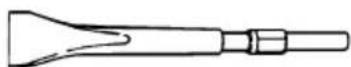
(1) Cutter
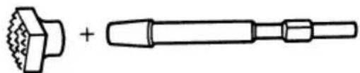
○Surface Roughing
natural_image
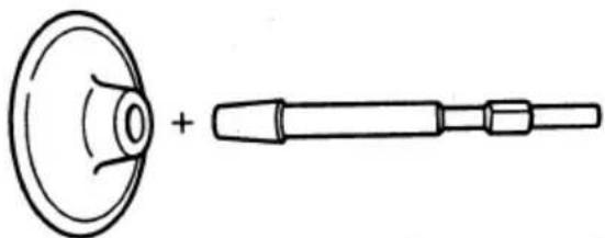
Technical line drawing of a mechanical component with two views: one showing a threaded end and the other a cylindrical shaft (no text or symbols)(1) Bushing Tool
(2) Shank
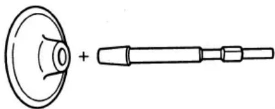
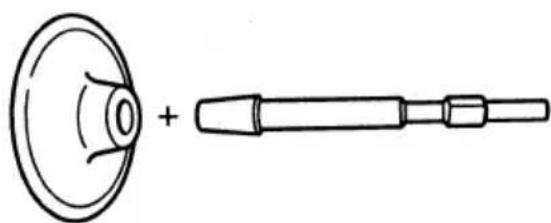
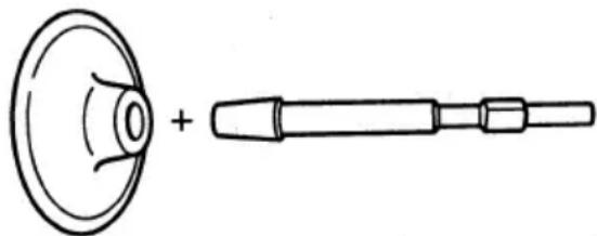
○Tamping
natural_image
Simple line drawing of a speaker with a circular head and a cylindrical tool (no text or symbols)(1) Rammer
(2) Shank
○Anchor work (for self-drilling anchors)
Anchor size
(for impact)
No. 30 W3/8
No. 40 W1/2
No. 50 W5/8
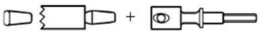
(1) Anchor Adaptor (for impact)
(2) Turning Handle

(3) Drift Key
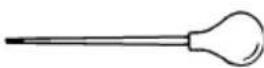
○Syringe (for debris removal)
○Scooping Work
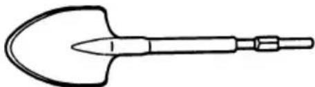
natural_image
Line drawing of a shovel with handle and pointed tip (no text or symbols)(1) Scoop
○Cylinder case cover (For heat insulation of cylinder case)
Cylinder case cover (rubber)
natural_image
Technical line drawing of a mechanical tool or drill bit with no visible text or symbols○Hammer Grease A
500 g (in a can)
70 g (in a tube)
30 g (in a tube)
Optical accessories are subject to change without notice.
APPLICATIONS
Breaking concrete, chipping off concrete, grooving, bar cutting, and driving piles.
Application examples:
Installation of piping and wiring, sanitary facility installation, machinery installation, water supply and drainage work, interior jobs, harbor facilities and other civil engineering work.
PRIOR TO OPERATION
1. Power source
Ensure that the power source to be utilized conforms to the power requirements specified on the product nameplate.
2. Power switch
Ensure that the power switch is in the OFF position. If the plug is connected to a power receptacle while the power switch is in the ON position, the power tool will start operating immediately, which could cause a serious accident.
3. Extension cord
When the work area is removed from the power source, use an extension cord of sufficient thickness and rated capacity. The extension cord should be kept as short as practicable.
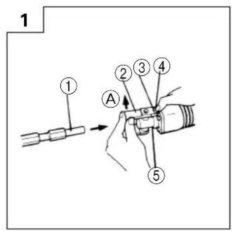
4. Tool Mounting
NOTE:
For tools such as a bull point and a cutter, use only HiKOKI genuine parts.
(1) Clean, then smear the tool shank with the grease provided.
(2) Press the push button, slightly lift the tool retainer in the direction of arrow A as shown in Fig. 1 to hook the tool retainer edge with the push button and engage the push button.
(3) Release your finger from the push button and further lift the tool retainer in the direction of arrow A.
NOTE:
First time when the tool retainer is lifted, remove your finger from the push button. If the push button is kept pressed, the edge of the tool retainer comes in contact with your finger and the tool retainer cannot be lifted.
(4) Fully insert the tool shank into the hexagonal hole in the front cover.
(5) Return the tool retainer to secure the tool.
NOTE:
Remove in the reverse order of installation.
WHEN THE PUSH BUTTON DOES NOT OPERATE SMOOTHLY
When the push button does not operate smoothly, please remove dirt from the inside through the outlet using a wire, etc. Then lubricate lubricating oil and push the push button several times to make it operate smoothly.
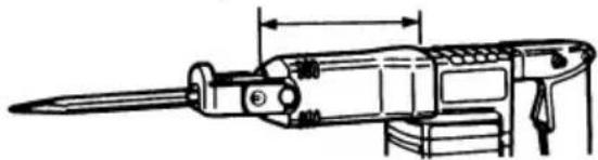
HOW TO USE THE DEMOLITION HAMMER (Fig. 3)
- After placing the tip of the tool in the base hole, switch ON.
- By utilizing the weight of the machine and by firmly holding the demolition hammer with both hands, one can effectively control the subsequent recoil motion.
Proceed at a moderate work-rate, the use of too much force will impair efficiency.
DRILLING AND DRIVING-IN OPERATION FOR SELF DRILLING ANCHORS
When self-drilling anchors (Fig. 4) are used, the anchors can be driven in. In this case, use the optional accessories for self-drilling anchors such as the anchor adapter.
- Attach the turning handle to the anchor adapter and turn the handle back and forth manually (Fig. 5). In this case, the plug is not attached to the anchor.
- When a predetermined depth has been attained, pull out the anchor tentatively (Fig. 6).
- By employing the syringe, blow out the debris.
- Attach the plug to the anchor tip and drive in the anchor again with the demolition hammer.
- After driving in the anchor, use the drift key to separate the anchor (Fig. 7).
- By employing a manual hammer or pliers, snap off the tapered portion of the anchor (Fig. 8).
CAUTION:
Since the snapped-off tapered portion will fly out, pay attention to the snapping direction.
GREASE REPLACEMENT
This machine is of full air-tight construction to protect against dust and to prevent lubricant leakage. This machine can be used without grease supplement for an extended period of time. However, perform the grease replacement to maintain the service life. Replace the grease as described below.
1. Grease Replacement Period
You should look at the grease when you change the carbon brush. (See item 4 in the section MAINTENANCE AND INSPECTION.)
Ask for grease replacement at the nearest authorized HiKOKI Service Agent.
In the case that you are forced to change the grease by yourself, please follow the following points.
2. How to replace grease
CAUTION:
Before replacing the grease, turn the power off and pull out the power plug.
(1) Remove the crank cover and wipe off the old grease inside (Fig. 9).
(2) Supply 30 g (the standard quantity to cover the connecting rod) of HiKOKI Electric Hammer Grease A to the crank case.
(3) After replacing the grease, install the crank case securely.
NOTE:
The HiKOKI Electric Hammer Grease A is of the low viscosity type. When the grease is consumed, purchase from an authorized HiKOKI Service Agent.
MAINTENANCE AND INSPECTION
1. Inspecting the tool
Since use of a dull tool will degrade efficiency and cause possible motor malfunction, sharpen or replace the tool as soon as abrasion is noted.
2. Inspecting the mounting screws
Regularly inspect all mounting screws and ensure that they are properly tightened. Should any of the screws be loose, retighten them immediately. Failure to do so could result in serious hazard.
3. Maintenance of the motor
The motor unit winding is the very “heart” of the power tool. Exercise due care to ensure the winding does not become damaged and/or wet with oil or water.
4. Inspecting the carbon brushes (Fig. 10)
The Motor employs carbon brushes which are consumable parts. When they become worn to or near the "wear limit", it could result in motor trouble. When an auto-stop carbon brush is equipped, the motor will stop automatically. At that time, replace both carbon brushes with new ones which have the same carbon brush Numbers shown in the figure. In addition, always keep carbon brushes clean and ensure that they slide freely within the brush holders.
5. Replacing a carbon brush
Loosen the set screw and remove the tail cover. Remove the brush cap and carbon brush. After replacing the carbon brush, do not forget to tighten the brush cap securely and to install the tail cover.
6. Service parts list
CAUTION
Repair, modification and inspection of HiKOKI Power Tools must be carried out by a HiKOKI Authorized Service Center.
This Parts List will be helpful if presented with the tool to the HiKOKI Authorized Service Center when requesting repair or other maintenance.
In the operation and maintenance of power tools, the safety regulations and standards prescribed in each country must be observed.
MODIFICATION
HiKOKI Power Tools are constantly being improved and modified to incorporate the latest technological advancements.
Accordingly, some parts may be changed without prior notice.
GUARANTEE
We guarantee HiKOKI Power Tools in accordance with statutory/country specific regulation. This guarantee does not cover defects or damage due to misuse, abuse, or normal wear and tear. In case of complaint, please send the Power Tool, undismantled, with the GUARANTEE CERTIFICATE found at the end of this Handling instruction, to a HiKOKI Authorized Service Center.
NOTE
Due to HiKOKI's continuing program of research and development, the specifications herein are subject to change without prior notice.
IMPORTANT
Correct connection of the plug
The wires of the main lead are coloured in accordance with the following code:
Blue: — Neutral
Brown: — Live
As the colours of the wires in the main lead of this tool may not correspond with the coloured markings identifying the terminals in your plug proceed as follows: The wire coloured blue must be connected to the terminal marked with the letter N or coloured black. The wire coloured brown must be connected to the terminal marked with the letter L or coloured red. Neither core must be connected to the each terminal.
NOTE
This requirement is provided according to BRITISH STANDARD 2769: 1984.
Therefore, the letter code and colour code may not be applicable to other markets except The United Kingdom.
Information concerning vibration
The measured values were determined according to EN60745.
The typical weighted root mean square acceleration value: 11.5 m/s ^2 .
natural_image
Technical line drawing of a mechanical component with two views: one showing a hexagonal nut and the other a cylindrical shaft (no text or symbols)(1) Stockerplatten
(2) Schaft
○Stampfen
natural_image
Simple line drawing of a speaker with a circular head and a cylindrical tool (no text or symbols)(1) Stampferplatten
(2) Schaft
natural_image
Line drawing of a hand tool with a pointed tip and handle (no text or symbols)(1) Spaten
natural_image
Technical line drawing of a mechanical tool or drill bit with no visible text or symbols○Hammer Schmierfett A
500 g (Dose)
70 g (in Tube)
30 g (in Tube)
natural_image
Technical line drawing of a mechanical component with two views: one showing a hexagonal nut and the other a cylindrical rod (no text or symbols)(1) Boucharde
(2) Queue
○Bourrage
natural_image
Simple line drawing of a speaker and a tool (no text or symbols)(1) Bourroir
(2) Queue
natural_image
Technical line drawing of a mechanical tool or drill bit (no text or symbols present)natural_image
Technical line drawing of a mechanical component with two views: one showing a hexagonal nut and the other a cylindrical rod (no text or symbols)natural_image
Simple line drawing of a circular component with a plus sign, next to a cylindrical tool (no text or symbols)(1) Pestello
(2) Gambo
natural_image
Simple line drawing of a shovel with a pointed tip and handle (no text or symbols)(1) Paletta
natural_image
Technical line drawing of a mechanical tool or drill bit with no visible text or symbolsnatural_image
Technical line drawing of a mechanical component with two views: one showing a hexagonal nut and the other showing a cylindrical shaft (no text or symbols)(1) Borstelhulpstuk
(2) Schacht
○Aanstampen
natural_image
Simple line drawing of a circular component with a plus sign, next to a cylindrical tool (no text or symbols)(1) Heiblok
(2) Schacht
natural_image
Line drawing of a shovel with handle and pointed tip (no text or symbols)(1) Schep
natural_image
Technical line drawing of a mechanical tool or drill bit with no visible text or symbols○Hamervet A
natural_image
Technical line drawing of a mechanical component with two views: one showing a flanged head and the other showing a threaded rod (no text or symbols)(1) Desbastadora
(2) Barrena
○Apisonamiento

natural_image
Simple line drawing of a speaker with a circular head and a cylindrical tool (no text or symbols)(1) Pisón
(2) Barrena
natural_image
Simple line drawing of a shovel with handle and base (no text or symbols)(1) Cuchara
natural_image
Technical line drawing of a mechanical tool or drill bit (no text or symbols present)○Grasa A para martillo
500 g (en una lata)
70 g (en un tubo)
30 g (en un tubo)
The exploded assembly drawing should be used only for authorized service center.
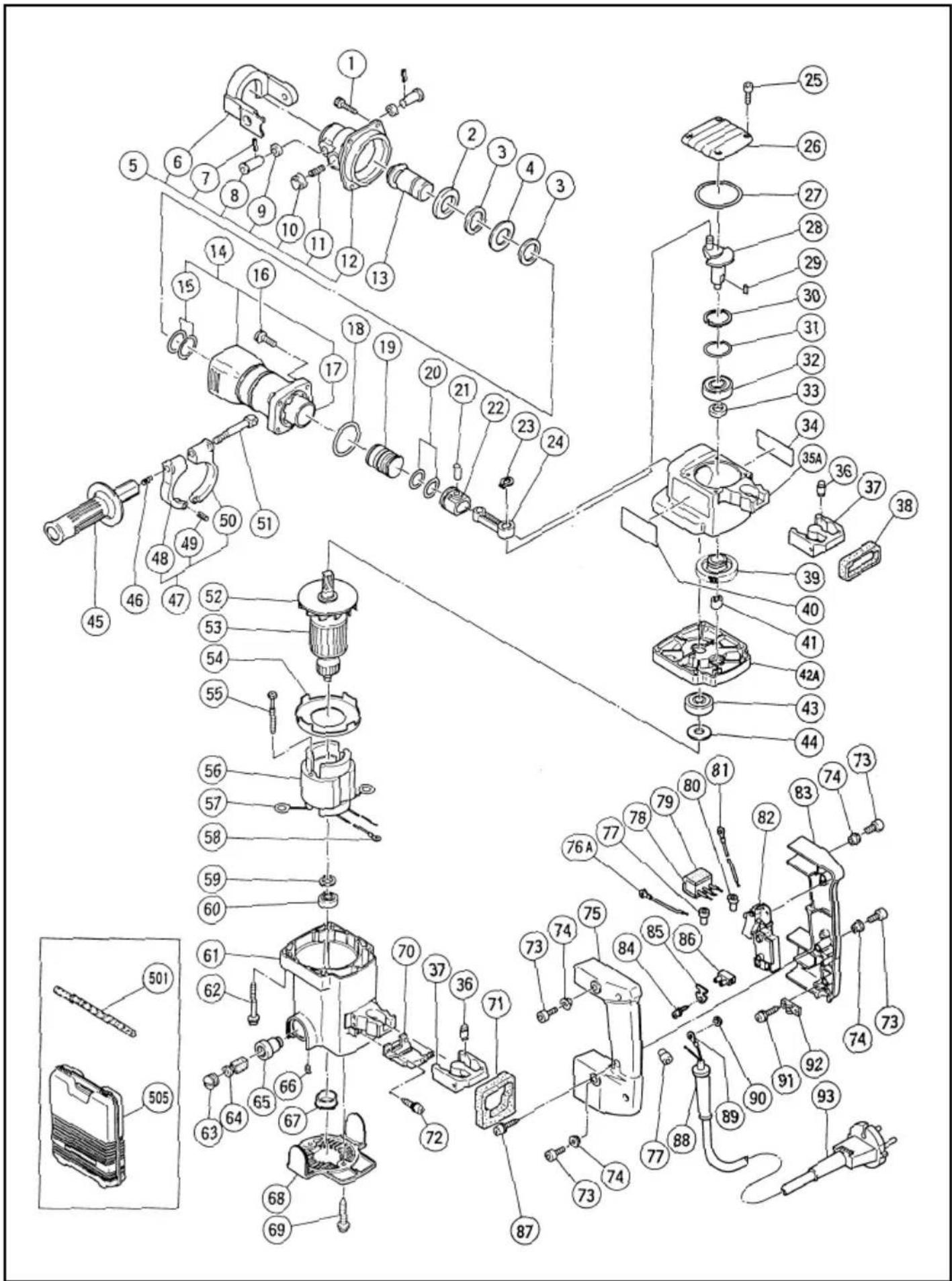
text_image
Exploded view diagram of a mechanical assembly with numbered parts for identification| Item No. | Part Name |
| 1 Nylock High Tension Bolt M7 × 25 | |
| 2 Damper Washer | |
| 3 Damper | |
| 4 Washer | |
| 5 Front Cover Ass'y | |
| 6 Retainer | |
| 7 Roll Pin D4 × 20 | |
| 8 Retainer Pin | |
| 9 Damper (B) | |
| 10 Pushing Button | |
| 11 Set Spring | |
| 12 Front Cover | |
| 13 Second Hammer | |
| 14 Cylinder Case Ass'y | |
| 15 O-Ring (A) | |
| 16 Nylock Bolt (W/Flange) M6 × 25 | |
| 17 Cylinder | |
| 18 O-Ring (S-48) | |
| 19 Striker | |
| 20 O-Ring | |
| 21 Piston Pin | |
| 22 Piston | |
| 23 Retaining Ring for D10 Shaft | |
| 24 Connecting Rod | |
| 25 Seal Lock Hex. Socket Hd. Bolt M4 × 12 | |
| 26 Crank Cover | |
| 27 O-Ring (S-55) | |
| 28 Crank Shaft | |
| 29 | Feather Key 4 × 4 × 10 |
| 30 Retaining Ring for D40 Hole | |
| 31 O-Ring (S-40) | |
| 32 Ball Bearing (6203DDUCMAV2S) | |
| 33 Oil Seal | |
| 34 Name Plate | |
| 35A Crank Case | |
| 36 Handle Damper | |
| 37 Transatory Unit | |
| 38 Handle Packing (A) | |
| 39 First Gear | |
| 40 BRAND Label | |
| 41 Needle Bearing (M661) | |
| 42A Gear Cover Ass'y | |
| 43 Ball Bearing (6201VVCMPS2S) | |
| 44 Washer (B) | |
| 45 Side Handle | |
| 46 Spring | |
| 47 Handle Holder Ass'y | |
| 48 Handle Holder (B) | |
| 49 Roll Pin D6 × 22 | |
| 50 Handle Holder (A) | |
| Item No. | Part Name |
| 51 | Handle Bolt |
| 52 | Fan |
| 53 | Armature |
| 54 | Fan Guide |
| 55 | Hex. Hd. Tapping Screw D5 × 50 |
| 56 | Stator Ass'y |
| 57 | Brush Terminal |
| 58 | Terminal |
| 59 | Washer (A) |
| 60 | Ball Bearing (608VVMC2EPS2L) |
| 61 | Housing Ass'y |
| 62 | Hex. Socket Hd. Bolt (W/Flange) M5 × 45 |
| 63 | Brush Cap |
| 64 | Carbon Brush |
| 65 | Brush Holder |
| 66 | Hex. Socket Set Screw M5 × 8 |
| 67 | Bearing Bushing (B) |
| 68 | Tail Cover |
| 69 | Tapping Screw (W/Flange) D4 × 16 |
| 70 | Internal Wire Holder |
| 71 | Handle Packing (B) |
| 72 | Tapping Screw (W/Washer) D5 × 20 |
| 73 | Seal Lock Hex. Socket Hd. Bolt M5 × 12 |
| 74 | Distance Piece (B) |
| 75 | Handle (B) |
| 76A | Internal Wire |
| 77 | Connector (50092) |
| 78 | Noise Suppressor |
| 79 | Support (B) |
| 80 | Connector (50091) |
| 81 | Internal Wire |
| 82 | Switch (A) |
| 83 | Handle (A) |
| 84 | Tapping Screw (W/Flange) D4 × 12 |
| 85 | Holder Plate |
| 86 | Pillar Terminal |
| 87 | Tapping Screw (W/Flange) D4 × 25 |
| 88 | Cord Armor |
| 89 | Terminal |
| 90 | Washer M4 |
| 91 | Tapping Screw (W/Flange) D4 × 16 |
| 92 | Cord Clip |
| 93 | Cord |
| 501 | Bull Point 280MM |
| 505 | Case |
Parts are subject to possible modification without notice due to improvements.
natural_image
Line drawing of a quill pen in an inkwell (no text or symbols)| English | Italiano | ||
| GUARANTEE CERTIFICATE1Model No.2Serial No.3Date of Purchase4Customer Name and Address5Dealer Name and Address(Please stamp dealer name and address) | CERTIFICATO DI GARANZIA1Modello2N° di serie3Data di acquisto4Nome e indirizzo dell'acquirente5Nome e indirizzo del rivenditore(Si prega di apporre il timbro con questi dati) | ||
| Deutsch | Nederlands | ||
| GARANTIESCHEIN1Modell-Nr.2Serien-Nr.3Kaufdaturn4Name und Anschrift des Kunden5Name und Anschrift des Händlers(Bitte mit Namen und Anschrift des Handlers abstempeln) | GARANTIEBEWIJS1Modelnummer2Serienummer3Datum van aankoop4Naam en adres van de gebruiker5Naam en adres van de handelaar(Stempel a.u.b. naam en adres vande de handelaar) | ||
| Français | Español | ||
| CERTIFICAT DE GARANTIE1No. de modèle2No. de série3Date d'achat4Nom et adresse du client5Nom et adresse du revendeur(Cachet portant le nom et l'adresse du revendeur) | CERTIFICADO DE GARANTIA1Número de modelo2Número de serie3Fecha de adquisición4Nombre y dirección del cliente5Nombre y dirección del distribudor(Se ruega poner el sellú del distribudor con su nombre y dirección) | ||
HiKOKI
| 1 | |
| 2 | |
| 3 | |
| 4 | |
| 5 |
natural_image
Line drawing of a quill pen with inkwell (no text or symbols)
natural_image
Line drawing of a quill pen in an inkwell (no text or symbols)Siemensring 34, 47877 willich, Germany
Tel: +49 2154 49930
Fax: +49 2154 499350
URL: http://www.hikoki-powertools.de
Hikoki Power Tools Netherlands B.V.
Brabanthaven 11, 3433 PJ Nieuwegein, The Netherlands Tel: +31 30
6084040
Fax: +31 30 6067266
URL: http://www.hikoki-powertools.nl
Hikoki Power Tools (U.K.) Ltd.
Precedent Drive, Rooksley, Milton Keynes, MK 13, 8PJ, United Kingdom
Tel: +44 1908 660663
Fax: +44 1908 606642
URL: http://www.hikoki-powertools.uk
Hikoki Power Tools France S.A.S.
Hikoki Power Tools Belgium N.V./S.A.
Koningin Astridlaan 51, B-1780 Wemmel, Belgium
Tel: +32 2 460 1720
Fax: +32 2 460 2542
URL http://www.hikoki-powertools.be
Hikoki Power Tools Italia S.p.A
Via Piave 35, 36077, Altavilla Vicentina (VI), Italy
Tel: +39 0444 548111
Fax: +39 0444 548110
URL: http://www.hikoki-powertools.it
Hikoki Power Tools Ibérica, S.A.
C/ Puigbarral, 26-28, Pol. Ind. Can Petit, 08227 Terrassa (Barcelona), Spain
Tel: +34 93 735 6722
Fax: +34 93 735 7442
URL: http://www.hikoki-powertools.es
