
GAK 750 B - Saw Güde - Free user manual and instructions
Find the device manual for free GAK 750 B Güde in PDF.


| Product type | Pole pruner (telescopic chainsaw) |
| Brand | Güde |
| Model | GAK 750 B |
| Order number | 94068 |
| Engine | Two-stroke engine, 25.4 cm³ |
| Max. power | 0.75 kW (1 PS) |
| Ignition | Electronic TCI |
| Fuel | Unleaded petrol / two-stroke oil mixture (1:40) |
| Fuel tank capacity | 0.6 L |
| Blade length | 25 cm |
| Total length (with cutting assembly) | 2.8 m |
| Weight | Approx. 5.5 kg |
| Usage | Tree pruning and undergrowth cutting from the ground |
| Chain lubrication | Biodegradable oil (dedicated tank) |
| Starting | Recoil starter, primer bulb, choke |
| Included equipment | Transport strap, chain guard |
| Safety | Stop switch, anti-kickback protection, chain guard |
| Maintenance | Cleaning, chain sharpening, drive shaft greasing |
| Warranty | According to enclosed warranty certificate |
| Minimum user age | 16 years (professional training possible) |
Frequently Asked Questions - GAK 750 B Güde
User questions about GAK 750 B Güde
0 question about this device. Answer the ones you know or ask your own.
Ask a new question about this device
Download the instructions for your Saw in PDF format for free! Find your manual GAK 750 B - Güde and take your electronic device back in hand. On this page are published all the documents necessary for the use of your device. GAK 750 B by Güde.
USER MANUAL GAK 750 B Güde
natural_image
Icon of an open book inside a black circle (no text or symbols)Deutsch
CE

natural_image
Industrial cleaning brush tool with black and red components, no visible text or symbols94068

natural_image
Close-up of a mechanical device with labeled parts, no visible text or symbolsAbb. 8
Abb. 9
Abb. 13
natural_image
Diagram of a chain drive mechanism with pulley and chain components (no text or labels)Abb. 12
natural_image
Close-up of hands using a power tool to cut a chain drive (no text or symbols visible)Abb. 14
natural_image
Close-up of a mechanical chain with a digital display and labeled component (no readable text or symbols)Abb. 15
natural_image
Mechanical component with a cylindrical part inserted into a housing, showing internal components and mounting holes (no text or symbols visible)Abb. 16
natural_image
Close-up of a metal chain saw and a mechanical clamp tool (no text or symbols visible)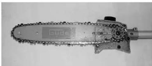
natural_image
Close-up of a metal chain-link robotic saw with visible teeth and chains (no text or symbols)Abb. 17
natural_image
Close-up of a mechanical chain or conveyor belt with a curved arrow indicating rotation (no text or symbols visible)Abb. 18
natural_image
Close-up of hands using a power tool to cut a chainsaw with a screwdriver (no visible text or symbols)Abb. 19
natural_image
Line drawing of a worker holding a long pole with tools, no text or symbols presentAbb. 20
Technische Daten
!!! Please read this instruction for operation carefully before putting the machine into operation !!!
A.V. 2 Surplus print even in shortened version requires permission. Technical changes reserved. Illustrations used represent examples.

Do you have any technical questions? Claim? Do you need spare parts or instructions for operation?
We are ready to help you quickly and without unnecessary bureaucracy at our site www.guede.com in the part Service. Please help us in helping you. In order to identify your machine in case of a claim we need its serial number, product number and year of production. All the data mentioned can be found at the type plate. Please write them down bellow to have them always handy:
Serial number:
Product number:
Year of production:
Phone.: +49 (0) 79 04 / 700-360 Fax: +49 (0) 79 04 / 700-51999 E-Mail: support@ts.guede.com
Unit
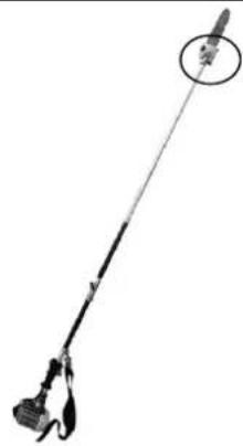
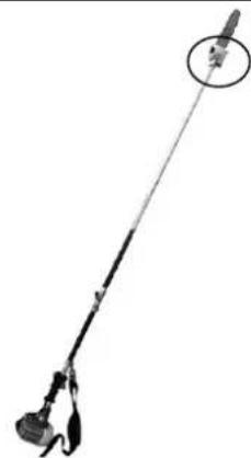
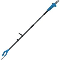
Professional care of trees and wood species done from the ground. With a pole 2.8 m long, considerable heights may be reached. Very small weight and user-friendly outfit provide conditions of safe and easy work. Included is a strand. Branded cutting assembly of premium quality. Driving mechanism with a stable metal pinion. Total length with the cutting assembly is 2.8 m. Quality electronic ignition secures high performance and good starting characteristics. With integrated fuel pump, starting is easy and free of any troubles even after prolonged periods of breaks and downtimes.
Scope of Delivery

Fig. 1


Fig. 2
Fig. 3
| 1. Extension tube | |
| 2. Engine | |
| 3. Switch | |
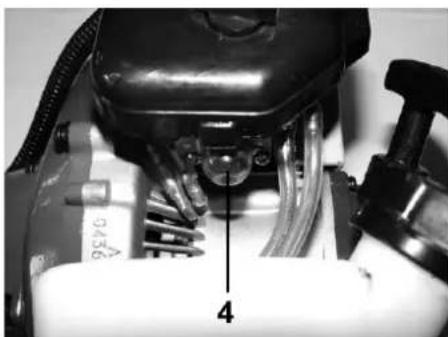
| 4. Holder | |
| 5. Wing screw | |
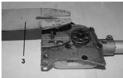
| 6. Saw head | |
| 7. Chain protection cover | |
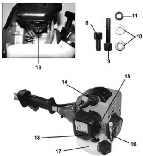
| 8. Inner hexagon screw | |
| 9. Inner hexagon screw | |
| 10. Washer | |
| 11. Retaining ring | |
| 12. Strap | |
| 13. Fuel pump | |
| 14. Spark plug socket |
| 15. | Choke | |
| 16. | Starter | |
| 17. | Fuel tank | |
| 18. | Air | filter |
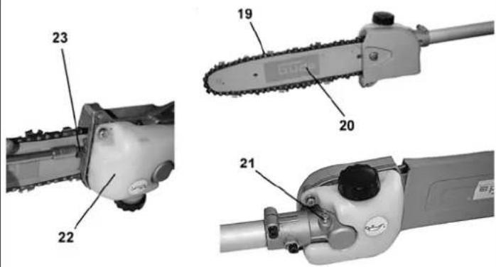
| 19. | Saw | chain |
| 20. | Bar | |
| 21. | Driving mechanism lubricator | |
| 22. | Oil tank | |
| 23. | Adjusting | screw |
Warranty
Warranty claims according to the warranty certificate attached.
General Safety Instructions
The instruction manual should be read in full prior to the initial use. In case of any doubts regarding connection and operation of the unit, turn to the manufacturer (servicing department).
TO GUARANTEE A HIGH DEGREE OF SAFETY, THE INSTRUCTIONS BELOW SHOULD BE OBSERVED:
CAUTION!
- Before getting down to work with the pruner, a flat and non-skid workplace providing for sufficient room and freedom of movement
- Observe any of the instructions contained herein before you start working with the pruner and in the course of the work.
- Do not operate the tool if you are tired or under effect of alcohol or drugs.
- Save these instructions.
- When not in use, the unit should be stored indoors in a dry place – out of reach of children.
• Any relevant regulations of accident prevention and other generally recognised safety technical rules should be observed. - Keep notebooks of professional association (VBG 7j).
• Use of other than genuine tools and accessories may result in a risk of accident.
• Upon completion of a repair or maintenance, any protection and safety devices should be re-installed immediately.
• Any damaged or defective protection devices should be replaced immediately.
• The persons working with the pruner should not be diverted to lack the concentration. - Clean the chips and cluttered parts of branched away from the working site.
- Do not use the pole pruner in windy weather or in a storm.
The pruner is intended for wood cutting only. Do not use it for other purposes. Do not use it to cut objects other than wooden.
Emergency Procedures
Give first aid appropriate to the injury and call a qualified medical help as fast as possible.
Protect the injured against more harm and put him/her in a resting position.
Unit Marking
Meaning of Symbols
Symbols shown below are used in this manual and on the unit:
Product Safety:
| CE | |||||
| Product conforming to respective EU standards |
Bans:
 |  |  |  |  | |
| General Prohibition (in combination with another pictograph) | No fire, no unprotected light, no smoking | Do not touch | Do not Reach in Equipment | Do not use the machine in wet weather |
Wanings :
 |  |  |  |  |  |
| Warning/caution | Beware of hazardous volrage | Beware of combustion promoting substances | Risk of stumble | Beware of health hazardous gases | Do not Reach in Equipment |
 |  |  | |||
| The machine should be used outside confined spaces only | Mind the risk of cutting | Keep safety distance |
Commands/Instructions:
 |  |  |  |  |  |
| Wear goggles | Wear protection headgear | Wear ear protectors | Wear safety footwear | Use protection gloves | Schutzkleidung benutzen |
 | |||||
| Read instruction manual before use |
Environment Protection:
 |  |  | |||||||
| Dispose of the waste in an environment-aware manner. | Cardboard packaging material may be delivered to a salvage point for recycling. | Defective electric and electronic devices or those to be disposed of should be delivered to a salvage point for recycling. | |||||||
Packaging:
 |  |  | |||
| Protect from rain | Packaging placing direction – up | Fragile! |
Technical Data:
 |  |  |  |  | ||
| Bar length Capacity 2-stroke engine | Tank capacity Weight | Noise level | ||||
Use in Compliance with Determination
The engine pole pruner is exclusively designed for pruning and treatment of other wood species from the ground.
The manufacturer shall not be held liable for any damages if the generally valid regulations and provisions contained herein are not observed.
Residual Hazard and Preventive Action
Mechanical Residual Hazards
| Threat Description Preventive | Action Residual Hazard | ||
| Bacjkash Turning the bar may result in backlash in the extension tube. | Work at sufficient speed and do not turn the bar. | ||
Noise Risk
Exposure to material and other substances hazards
| Gefährdung | Beschreibung | Schutzmaßnahme(n) | Restgefahr |
| Contact, inbreath Breathing in may be extremely dangerous or even fatal to health. | Use the unit outdoors only Work up the wind . | ||
| Fire or explosion The unit works on an easily inflammable mixture of fuel that may catch fire at refuelling e.g. | Do not replenish the fuel near an open fire. Do not smoke . | ||
Failure to Observe Human-Factor Principles
| Gefährdung | Beschreibung | Schutzmaßnahme(n) | Restgefahr |
| Negligence in the use of personal protection equipment | Negligence in the use of personal protection equipment may result in severe injuries. | Use all kinds of personal protection equipment. | |
| Human behaviour/human error | Focus on your job Cannot be excluded completely | ||
Other risks
| Gefährdung | Beschreibung | Schutzmaßnahme(n) | Restgefahr |
| Slipping, stubbing or falling Other persons may be exposed to danger in result of somebody's slipping or stubbing | Keep other persons as a reasonable distance away from the working area. | ||
Disposal
The instructions for disposal are expressed in the pictographs on the unit or the packaging. For description of individual meaning see chapter "Unit Marking".
Operator Requirements
The operator is required to read the instruction manual carefully before using the unit.
Qualification
No special qualification is required except for detailed briefing by a specialist.
Minimum Age
The unit shall be operated by persons above 16 years of age.
Operation by juvenile operators is an exception, if it is as a part of professional training under supervision of a teacher with an aim to obtain skills.
Training
The unit operation requires an adequate briefing. No special training is required.
Technical Data
| Engine: 2-taktní motor | |
| Maximum output 0,75 kW (1 PS) | |
| Tank capacity 0,6 L | |
| Mixture ratio 1:40 | |
| Barlength | 25 cm |
| Weight ca | ca. 5,5 kg |
| Ordering No. | 94068 |
Transport and Storage
If the pruner is to be stored for a period above 1 month, steps described below should be taken:
• Empty the fuel and the oil tanks.
- Remove and clean the guide bar and the chain.
- Clean the bar and the chain by dipping in kerosene solvent or fine soap solution.
• Dry the guide bar and the chain.
- Put the chain in a tank filled with oil to prevent corrosion.
- Apply a thin oil layer on the guide bar.
- Wipe the pruner interiors with soft cloth wetted with fine soap solution.
- Store the pruner at an elevated locked place out of the reach of children.
• Store the pruner in a plastic bag at a dry place or put the cover included on the guide bar.
Assembly and Initial Putting in Operation
| Assembly Group 1 Parts of Delivery | ||
 Fig. 4 Fig. 4 | Fig. 1 – Pos. 1Fig. 1 – Pos. 6 |  |
| Assembly Group 2 Assembly Groups | Required Parts of Delivery | ||
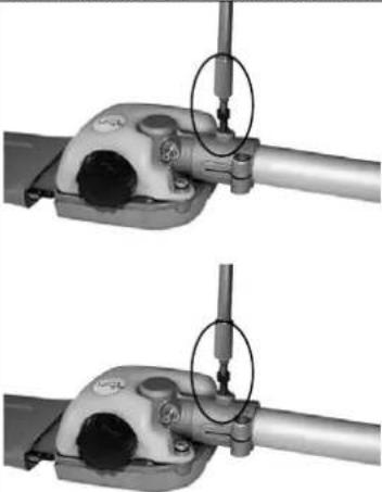 Fig. 5 Fig. 5 | Assembly Group 1 | Fig. 1 – Pos. 8Fig. 1 – Pos. 102 xFig. 1 – Pos. 9Fig. 1 – Pos. 11 |  |
| Assembly Group 3 Assembly Groups | Required Parts of Delivery | ||
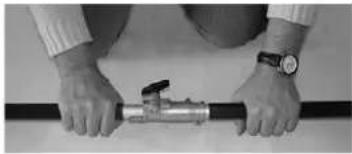
 | Assembly Group 2 | Fig. 1 – Pos. 4Fig. 1– Pos. 3 |  |
 | |||
 | |||
| Fig. 6 |
| Assembly Group 5 Assembly Groups Required Parts of Delivery | |||
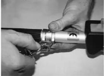 | Assembly Group 4 | Fig. 1 – Pos. 12 |  |
 | |||
| Fig. 7 | |||
 Fig. 8 Fig. 8 | Pour the 2-stroke fuel in the respective hole (1). Beware of spills.(Risk of ignition).Move from the place of replenishment at a distance of 3 metersat least. Never start the unit in confined or poorly ventilatedspaces.Filling:Mix leadless petrol with branded oil for two-stroke air-cooledengines at a ratio of 1:40. |
Fig. 8

Fig. 9
- Remove oil tank cover (1).
- Pour biologically degradable chain oil in the oil tank (2). Application of naturally degradable grain grease of rape of sunflower oil on guide rail and chain is recommended.
- Replace the oil tank cover (1) and tighten it well. That will prevent oil leakage from the tank.
- Wipe any excess oil off. Empty the oil tank after every use (2) for the oil not to pour off.

Take care for the fuel and the oil not to soak in the soil.
Safety Instructions for First Putting in Operation
Before putting the engine pole pruner in operation, check whether it is in safe serviceable condition. Never start the unit if in doubt.
Observe the following steps in particular:
- Correct installation of separate parts
- Ease of all the switches run.
- Safe positioning of the spark plug socket. If the socket is slack, the spark may put the fuel-air mixture on fire.
- Never use the pruner if the saw or handle are damaged, poorly adjusted or not safely assembled, when the starter is not working. The chain should stop if the starter is on. Defective starters should be replaced at one only authorised servicing centre.
- Do not use the pruner in a windy or stormy weather.
- Beware of falling branches. Inspect the tree before pruning. Make space for falling branches and watch out for the direction of fall.
- Do not use the pruner for cutting sprouts or shrubs.
- Do not work in the vicinity of flammable liquids or gases.
• Defective chain should be replaced immediately. - Keep your tools clean and sharp, your work will be better and safer.
People around should be kept at a safe distance.
Operation


natural_image
Close-up of a mechanical device with labeled parts (no readable text or symbols)- Shift the switch (1) towards the handle. At cold start, the choke switch (5) has to be pushed upwards.
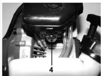
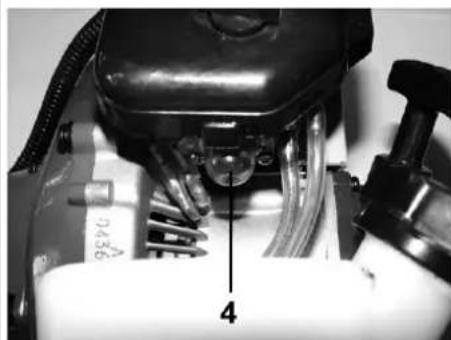
- Press the fuel pump (4) ca 8-10 times to fill the fuel system. (2-3 times at a normal operation).
- Put your hand on the handle and release the cut-out. Push the start button in and press the lock button (2). Keepit pressed and let the engine button go. The set-up is not ready (2).
- Hold the saw with one hand on the clasp (4). Pull the launching cable (6), until the engine runs. CAUTION! Do not pull the cable too far! Watch out the running chain.
- When the engine is running, shift the choke switch downwards again (5). Give full throttle 2-3 times and start working.
- After switching the machine off put the switch to (1) „STOP“ (in the direction of edge)
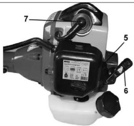
Fig. 10

Fig. 13
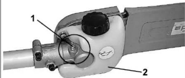
- Lubricate the drive shaft in the extension tube by pressing the lubricating pin (1).
- Fill the oil tank (2) with the indicated chain oil (see Chapter 5).
Chain Tension Set Up

WARNING: Always pay attention to the chain tension. A slackened chain will increase the risk of backlash. If d, the chain could spring out of the guide, could cause injury to the operator and get damaged. A slackened chain is very quickly and the sprocket wheel and the guide bar wears out

natural_image
Close-up of hands using a power tool to cut a chainsaw with a screwdriver (no visible text or symbols)
natural_image
Mechanical assembly diagram showing a motor and gear assembly with no visible text or symbolsFig. 11
- Prior to the chain tension set up make sure that the guide bar nut (1) is tightened by hand only.
- Turn the setting screw (2) clockwise until the chain fits but may be moved with ease.
The chain should fit evenly at every point of the bar but should not be too tense or clasped.

natural_image
Technical line drawing of a chain drive mechanism with pulley and chain components (no text or symbols)Fig. 12
- The chain should move freely. If it does not, release it by turning the setting screw (2) anticlockwise. - Once the chain is tensioned correctly, tighten the guide bar nut. If it is not tight, the guide bar will move and slacken the chain tension. This would increase a risk of backlash that may cause damage to the unit.
Notice: A new chain tends to extend. Check the new chain after initial minutes of operation. Le the chain cool down and reset the chain tension.
Bar and Chain Replacement

natural_image
Close-up of hands using a power tool to cut a chainsaw with a screwdriver (no visible text or symbols)Fig. 14
- Release the bar nut (1) - Remove the chain bar nut (1) and take the cover off

natural_image
Close-up of a chain-link robotic saw with a digital display and labeled component (no readable text or symbols)Fig. 15
- Remove the chain (2)

natural_image
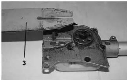
Mechanical component with a cylindrical part and mounting holes, labeled with number 3 (no text or symbols on the main subject)Fig. 16
- Remove the bar (3) from the guide.

natural_image
Three mechanical components: a chain-linked saw, a flat blade with a handle, and a mechanical lever (no visible text or symbols)m = 311
- Now, the bar or the chain may be exchanged. - Conduct the chain round the bar and insert it in the guide.

natural_image
Close-up of a mechanical chain-link robotic saw with visible teeth and mounting bracket (no text or symbols)Fig. 17


Operation Safety Precautions

Avoid the backlash. The backlash may cause severe injuries.
Do not use the unit if standing on a ladder or another unstable support or if your footing is not firm.
Call a specialist to assist if the circumstances require a use of heavier units.
Remember what are the conditions of your work. The unit produces toxic fumes as soon as the engine is running. These exhaust gases may be odourless and invisible. Therefore, never operate the pruner in confined or poorly ventilated spaces. Make sure to have good lighting. Take care in wet weather, on snow, ice, slope, rough ground and provide for safe footing.
- Do not use the unit until you have read the operating instructions.
- Observe all the directions contained herein.
- Your behaviour to other persons must be responsible.

Caution: Beware of falling branches.
Step by Step Instructions
- Prepare the engine pole pruner for operation taking steps described in Chapter 5 "First Putting in Operation" and start according to Chapter 6, Operation.
- Wear the right clothing and anti-skid footwear
- Hold the pruner at due spots of grasp with both the hands Hold the pruner safely. The thumbs and fingers should embrace the pruner pole.
Mind proper footing, distribute the weight evenly in both the feet.
- At the beginning, place the moving chain on the wood or a branch. Hold the pruner at a place strongly to avoid jerks or skids (to the sides). Work with the chain moving at the full speed if possible.
- Conduct the pruner with a light pressure. Do not force on it not to overload the engine. The pruner performance is better and safer at the highest speed possible.
- Remove the pruner from the cut slit when the engine is running at full. Push the button to switch the machine off. Mind that the unit has to be still completely and only then it may be put off.

natural_image
Line drawing of a worker holding a long tool with a bucket, labeled 'Abb. 20' (no other text or symbols)Faults – Causes – Troubleshooting
CAUTION: ALWAYS CHECK POWER FUSES FIRST!
| Fault | Cause | Troubleshooting |
| The pruner runs but is not cutting | The chain is fitted in reverse on the guide bar | Refer to the assembly of guide bar and chain |
| The pruner will cut only if the speed is high, result is only chips with several larger parts. | The chain is blunt | Refer to the saw chain sharpening |
| No oil is supplied to chain | 1. Oil tank empty.2. Oil too thick. | 1. Replenish oil tank.2. Use the right oil, oil tank filling. |
| 1. Chain slackened | ||
| The chain gets loosen from the guide bar | 1. Tighten the chain see Chain Tension set-up (see Operation)2. see Guide Bar and Chain Installation | |
| 2. Guide bar and chain misassembled | ||
| Smoke from unit | 1. Oil content in the fuel too high. 1. Use 1:25 mixture . | |
| Oil leaking from the unit | 1. Oil tank cover not closed sufficiently | 1. Tighten the oil tank cover. Notice: empty the oil tank when the saw is out of use |
Checks and Maintenance
Notice: Observe the saw maintenance instructions. Any maintenance not included herein should be done by an authorised servicing workshop.
Saw exteriors cleaning
Keep the saw exteriors clean. Use a soft cloth wetted in fine soap solution and wipe off the saw exteriors.

Warning:
• The chain cutting edges are sharp. Wear protective gloves any time when handling the chain.
- Saw exteriors cleaning
- Do not dip the saw in liquids.
• Do not use any detergents containing ammonia, chlorine or flour emery
• Do not use detergents chlorine, carbon chloride kerosene or petrol
Checks and Maintenance Safety Instructions
The unit may be a reliable tool only if maintained and cared for on a regular basis. Insufficient maintenance and care may cause unexpected accidents and injuries.
Uneven wear is the cause if guide bar problems most frequently. They may be due to inappropriate sharpness of the chain cutting elements and poor adjustment of the depth limiters. If the bar is worn unevenly, the bar rail will get wider. The saw will chatter then and the rivets get loosen. The saw cutting will not be straight. The chain bar should be replaced. The bar should be checked before the saw is sharpened. A worn or defective bar is not safe and damages the chain and makes cutting difficult.
- Remove the guide bar from the unit.
• From time to time, clean the guide bar slit from the sawdust. Use a wire or a filling knife for it. - After repeated grinding with a file, the chain should be sharpened at a servicing centre or on a sharpening machine to secure even sharpening.
- Remove any roughness on the guide bar sides. Use a flat file to make the corners true.
Chain Sharpening

WARNING:
- Cutting edges are sharp. Wear protective gloves when handling the chain.
The chain should be kept sharpened. The cutting job will be faster and safer then. A blunt chain will cause unnecessary wear of the sprocket wheel, guide bar, chain and motor. The chain is blunt if it is necessary to force it against the wood and cutting then results in sawdust and several larger chips.
Tip: Use some of the saw chain sharpeners by Güde.
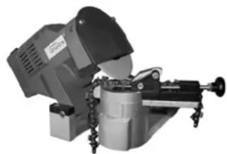
GS 650 saw chains sharpener
natural_image
Industrial machine with mechanical components and wheels (no visible text or symbols)Rugged universal sharpener of all common chains to be fitted. Skala high-efficiency motor, 2 x 35°, sharpening angle may be easily adjusted by manual wheel, guide bar and adjustable stop. Chain fixing by retaining screws. Easy sharpening of cutting elements by force applied on the motor casing.
EAN 40 15671 94090 2
Article-Nr. 94090
Profi 2500 saw chain sharpener

natural_image
Mechanical clamp or vise device with adjustable handle and base (no visible text or symbols)Professional chain sharpener, suitable for any common types of saws,
High-efficiency motor, no change of clamping chain, Both teeth positions may be sharpened by a swivelling jig and grinding head, lighting of the worked part included (230 Volt, 15 Watt, E14). All settings easily controlled, basic body of aluminium casting without twists, grinding head enabling easy turns at grinding and automatic reverse setting of the head.
Included 1 disk 145 x 22,3 x 3,2mm, 1 disk 145 x 22,3 x 4,7 mm, with an oil-stone and grinding gauge.
EAN: 40 15671 94131 2
Article-Nr. 94131
Manual sharpening with file
- Use a file guide for filing at 30^ .
- Adjust the chain for it to be tensioned properly Fasten the guide bar in the vice with care. Notice: Never fasten the chain.
- Insert a 4-mm round file (connected to a file guide) in the slit between the top plate and the depth limiter on the chain. The file guide should rest on both the top plate and the depth limiter
(Notice: File in the centre of the guide bar.) - Hold the file guide straight. Make sure that the 30^ mark on the file guide runs in a parallel with the guide bar centre line. That will guarantee that the cutting element are filed at an angle of 30^ .
File the element in inside-outside direction until it is sharp. File in one direction only.
Notice: Two or three strokes of the file should be sufficient to sharpen the cutting element.
- When the cutting element is sharpened, push the chain forward and proceed with a following element. File all the cutting elements on one side of the chain. Repeat the procedure on the other side.
Cutting elements depth limiters filing
The depth limiter clearance will decrease if the cutting elements are sharpened. The cutting elements depth limiters should be readjusted following every second or third sharpening.
• Fit the depth gauge (0.635 mm) firmly on two cutting elements tips.
• Make sure that the limiter slides into the depth gauge slit
• Use a medium sized flat file. File the depth gauge and the depth limiter straight.
- Remove the depth gauge. Using a flat file, dress the cutting element depth limiter corner.
Saw chain replacement
Replace the chain any time when the cutting elements are too worn after repeated sharpening or break of the chain is imminent. Only use the replacement chain mentioned herein. The sprocket wheel has to be replaced as well when the chain is being replaced. Proper drive of the chain will be provided then.. Notice: The chain and sprocket wheel are shown in chapter Chain and Bar Replacement.
Check and Maintenance Schedule
| Time Interval Description Other Details | ||
| After every use | Clean sawdust thoroughly from the unit | |
| As needed | Sharpen the chain | |
| As needed | Replenish oil | |
| After every 3^rd use | Lubricate drive shaft (see chapter 6.2) | |


Fig. 1

Fig. 2

Fig. 3
Fig. 9

natural_image
Close-up of a mechanical device with labeled parts (no readable text or symbols)Fig. 13
natural_image
Close-up of hands using a power tool to cut a chainsaw with a screwdriver (no visible text or symbols)
natural_image
Mechanical assembly diagram showing a rotating component with labeled parts (no readable text or symbols)Fig. 11
natural_image
Technical line drawing of a chain drive mechanism with inset close-up views (no text or symbols)Fig. 12
natural_image
Close-up of hands using a power tool to cut a chain-coated metal saw (no text or symbols visible)Fig. 14
natural_image
Close-up of a Gude chain saw with labeled component (no readable text or symbols beyond label)Fig. 15
natural_image
Three mechanical components: a chain-linked saw, a flat saw blade, and a wire-coated tool (no visible text or symbols)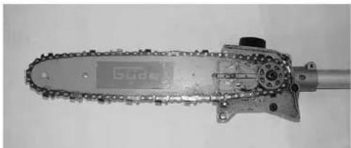
natural_image
Close-up of a metal chain-linking tool with visible teeth and chains (no text or symbols)Fig. 17
natural_image
Close-up of a mechanical chain track with visible joints and components, no text or symbols presentFig. 18
natural_image
Close-up of hands using a power tool to cut a chainsaw with a screwdriver (no visible text or symbols)Fig. 19
natural_image
Line drawing of a worker holding a long pole with tools, no text or symbols presentAbb. 20
natural_image
Industrial machine with cylindrical component and mechanical arms (no visible text or symbols)natural_image
Mechanical clamp or vise device with adjustable handle and base (no visible text or symbols)Obr. 1


Obr. 2
Obr. 3
natural_image
Close-up of hands operating a mechanical tool with a circular annotation highlighting a component (no visible text or symbols)Obr. 4
Obr. 1 – Poz. 1
Obr. 1 – Poz. 6
natural_image
Diagram of a handheld device with a circular inset showing a connector or sensor (no text or symbols present)Montážní skupina 2

natural_image
Mechanical assembly diagrams showing two configurations of a tool or clamp mechanism (no text or symbols present)Obr. 5
natural_image
Simple line drawing of a handheld device with a circular annotation highlighting a specific component (no text or symbols present)natural_image
Close-up of a mechanical device with black and white components, labeled with number 1 (no visible text or symbols on the device itself)Obr. 8
natural_image
Close-up of a mechanical device with labeled parts (no readable text or symbols)natural_image
Diagram of a chain drive mechanism with pulley and chain components (no text or labels)Obr. 13
natural_image
Close-up of hands using a power tool to cut a chainmail (no text or symbols visible)Obr. 14
natural_image
Close-up of a mechanical chain with a visible Gide blade and gear (no text or symbols)Obr. 15
• Vyjměte řetěz (2)
natural_image
Mechanical component with a cylindrical housing and mounting holes, labeled with number 3 (no text or symbols on the object itself)Obr. 16
natural_image
Three mechanical components: a chain-linked saw, a flat saw blade, and a wire clamp (no visible text or symbols)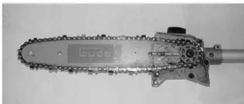
natural_image
Close-up of a metal chain-link robotic saw with visible chains and a small sensor (no text or symbols)Obr. 17
natural_image
Close-up of a mechanical chain with chains and gears, showing a curved arrow indicating motion (no text or symbols visible)Obr. 18
natural_image
Close-up of hands using a power tool to cut a GDUe chain (no text or symbols visible)Obr. 19
natural_image
Line drawing of a worker holding a long pole with tools, no text or symbols presentAbb. 19
natural_image
Industrial machine with mechanical components and mounting base (no visible text or symbols)natural_image
Mechanical clamp or vise device with adjustable arms and a central hub (no visible text or symbols)Obr. 1

Obr. 2
Obr. 3
natural_image
Close-up of hands holding a mechanical component with chains and a metallic clip (no visible text or symbols)
natural_image
Mechanical device with attached lever and belt (no visible text or symbols)
natural_image
Simple line drawing of a pole with a small object attached, no text or symbols present
natural_image
Close-up of a mechanical device with labeled parts, no visible text or symbolsObr. 8
Obr. 9
natural_image
Close-up of a mechanical device with labeled parts (no readable text or symbols)Obr. 13
natural_image
Two-step installation of a chain drive being cut, showing tool path and component details (no text or symbols)Obr. 11
natural_image
Technical line drawing of a chain drive mechanism with inset close-up views (no text or symbols)Obr. 12
natural_image
Close-up of hands using a power tool to cut a chainback (no text or symbols visible)Obr. 14
- Uvol'nite maticu ret'azovej čepele (1) - Odstráňte maticu ret'azovej čepele (1) a odoberte kryt.

natural_image
Close-up of a Gude chain saw with labeled component (no readable text or symbols beyond label)Obr. 15
• Vyberte ret'az (2)
natural_image
Close-up of a mechanical component with a cylindrical shaft and mounting holes, labeled with number 3 (no text or symbols on the object itself)Obr. 16
• Vytiahnite čepel' (3) z vedenia.

natural_image
Close-up of a metal chain saw and a wire crimping tool (no text or symbols visible)natural_image
Close-up of a metal chain-link robotic saw with visible teeth and chains (no text or symbols)Obr. 17

natural_image
Close-up of a mechanical chain with chains and components, no visible text or symbolsObr. 18
• Rešpektujte smer chodu ret'aze.

natural_image
Close-up of hands using a tool to cut a chain drive (no text or symbols visible)Obr. 19
- Nasad'te opät' kryt a zaskrutkujte ho (1). - Nakoniec ret'az znovu primerane napnite.
natural_image
Line drawing of a worker holding a long tool, labeled 'Obr. 20' (no other text or symbols)natural_image
Industrial machine with mechanical components and mounting base (no visible text or symbols)natural_image
Mechanical clamp or vise device with adjustable arms and a central hub (no visible text or symbols)Ábra. 1

Ábra. 2
Ábra. 3
natural_image
Close-up of hands operating a mechanical tool with a circular annotation highlighting a component (no visible text or symbols)Abra. 4
Abra. 1 – Poz. 1
Abra. 1 – Poz. 6

natural_image
Simple line drawing of a handheld device with a circular annotation highlighting a component (no text or symbols)natural_image
Mechanical assembly diagrams showing two configurations of a tool or clamp mechanism (no text or symbols present)Abra. 5
Szerelési csoport 1
Abra. 1 – Poz. 8
Abra. 1 – Poz. 102 x
Abra. 1 – Poz. 9
Abra. 1 – Poz. 11

natural_image
Mechanical device with a lever and attached sensor, shown in black and white (no text or symbols visible)natural_image
Close-up of a mechanical device with labeled parts, no visible text or symbols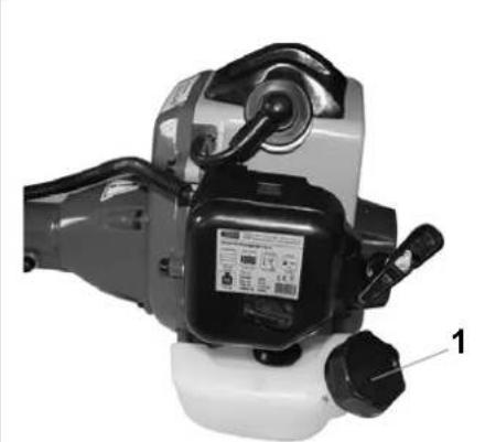
natural_image
Close-up of a mechanical device with labeled parts, no visible text or symbolsnatural_image
Close-up of a mechanical device with labeled parts (no readable text or symbols)
Ábra. 10
Ábra. 13
natural_image
Two-step installation of a chainsaw being cut, showing tool path and component details (no text or symbols)Ábra. 11
natural_image
Technical line drawing of a chain drive mechanism with inset close-up views (no text or symbols)Ábra. 12
natural_image
Close-up of hands using a power tool to cut a chainback (no text or symbols visible)Ábra. 14
natural_image
Close-up of a mechanical chain-link robotic saw with a digital display on the blade (no visible text or symbols)Ábra. 15
natural_image
Mechanical component with a cylindrical part inserted into a housing, labeled '3' (no visible text or symbols on the main subject)Ábra. 16
natural_image
Three mechanical components: a chain-linked saw, a flat blade with a handle, and a wire clamp (no visible text or symbols)natural_image
Close-up of a metal chain-link robotic saw with chains and a visible 'Slade' logo (no text or symbols on the saw itself)Ábra. 17

natural_image
Close-up of a mechanical chain with chains and components, no visible text or symbolsÁbra. 18
natural_image
Close-up of hands using a tool to cut a chain drive (no text or symbols visible)Ábra. 19
natural_image
Line drawing of a worker holding a long tool with a mounted device (no text or symbols)Abb. 20
natural_image
Industrial machine with mechanical components and mounting bracket (no visible text or symbols)natural_image
Mechanical clamp or vise device with adjustable handle and mounting bracket (no visible text or symbols)Afb. 1


Afb. 2
Afb. 3
| 1. | Verlengbuis | 15. | Choke |
| 2. | Motor | 16. | Starter |
| 3. | Schakelaar | 17. | Brandstoftank |
| 4. | Greep | 18. | Luchtfilter |
| 5. | Vleugelschroef | 19. | Zaagketting |
| 6. | Zaagkop | 20. | Zaagbalk |
| 7. | Zaagkettingbescherming | 21. | Smeernippel voor drijfwerk |
| 8. | Inbusbout | 22. | Olietank |
| 9. | Inbusbout | 23. | Afstelschroef |
| 10. | Onderlegring | ||
| 11. | Borgring | ||
| 12. | Draaggordel | ||
| 13. | Brandstofpomp | ||
| 14. | Bougieplug |
Garantie

natural_image
Close-up of a mechanical device with labeled parts (no readable text or symbols)
Afb. 10
Afb. 11
natural_image
Two-step installation of a chainsaw being cut, showing tool path and mounting detail (no text or symbols)Afb. 12
natural_image
Technical line drawing of a chain drive mechanism with inset showing close-up views (no text or symbols)Afb. 13
natural_image
Close-up of hands using a power tool to cut a chainsaw with a screwdriver (no visible text or symbols)Afb. 14
natural_image
Close-up of a chain-link robotic saw with a labeled component (no readable text or symbols)Afb. 15
natural_image
Three metal tools: a chain-linking saw, a flat blade with a handle, and a mechanical clamp (no visible text or symbols)
natural_image
Close-up of a metal chain-link robotic saw with visible teeth and chains (no text or symbols)Afb. 17
natural_image
Close-up of a mechanical chain with visible teeth and metal components, no text or symbols presentAfb. 18
natural_image
Close-up of hands using a power tool to cut a chainback (no text or symbols visible)Afb. 19
natural_image
Line drawing of a worker holding a long tool, labeled 'Afb. 20' (no other text or symbols)natural_image
Industrial robotic device with mechanical components and mounting base (no visible text or symbols)natural_image
Mechanical clamp or chisel device with no visible text or symbolsFig. 1

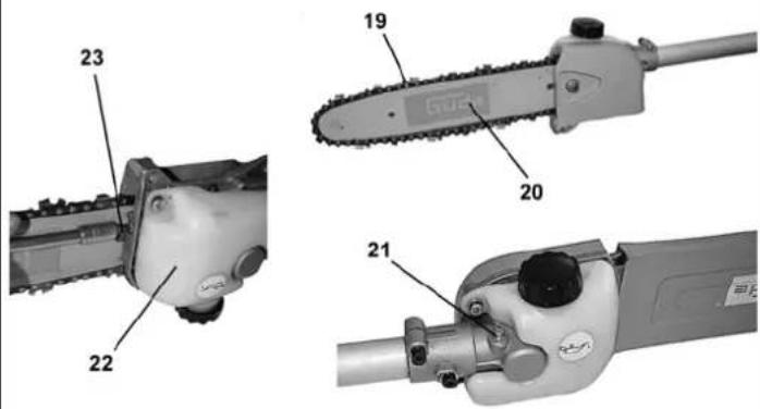
Fig. 2
Fig. 3
natural_image
Close-up of hands operating a mechanical tool with a circular annotation highlighting a component (no visible text or symbols)Fig. 4
Fig. 1 - Pos. 1
Fig. 1 - Pos. 6
natural_image
Mechanical device with lever and attached sensor (no visible text or symbols)natural_image
Two mechanical tool tips on a pipe fitting, showing different angles and mounting points (no text or symbols visible)natural_image
Simple line drawing of a handheld device with a circular annotation highlighting a component (no text or symbols)natural_image
Close-up of a mechanical device with labeled parts, no visible text or symbols
natural_image
Close-up of a mechanical device with black and white components and a labeled component (1), no visible text or symbols.Fig. 9
natural_image
Close-up of a mechanical device with labeled parts (no readable text or symbols)Fig. 13
natural_image
Two-step installation of a chain drive: top shows hand turning a tool, bottom shows close-up of mechanical components (no text or symbols visible)Fig. 11
natural_image
Technical line drawing of a chain drive mechanism with gear and pulley components (no text or symbols)Fig. 12
natural_image
Close-up of hands using a power tool to cut a chainback (no text or symbols visible)Fig. 14
natural_image
Close-up of a Gude chain saw with labeled component (no readable text or symbols beyond label)Fig. 15
- Estrarre la catena (2)

natural_image
Close-up of a mechanical component with a cylindrical shaft and mounting holes, labeled with number 3 (no text or symbols on the object itself)Fig. 16
natural_image
Three mechanical components: a chain-linked saw, a flat blade with a handle, and a wire clamp (no visible text or symbols)natural_image
Close-up of a metal chain-link robotic saw with visible teeth and chains (no text or symbols)Fig. 17


natural_image
Line drawing of a worker holding a long tool, labeled 'Abb. 20' (no other text or symbols)natural_image
Industrial machine with mounted components and a cylindrical housing (no visible text or symbols)natural_image
Mechanical clamp or vise device with adjustable arms and a handle (no visible text or symbols)EC Declaration of Conformity
That the following Appliance complies with the appropriate basic safety and health requirements of the EC Directive based on its design and type, as brought into circulation by us.
In a case of alternation of the machine, not agreed upon by us, this declaration will lose its validity.
Machine description:
Artikel-Nr.:
94068
Article-No.:
Applicable EC Directives:
89/336/EG_93/68/EG
97/68/EG_2004/26/EG
Applicable harmonized
- 55012:2002/+A1:2005
Standard:
Type-Approval-Nr.:
e11*97/68/SA*2004/26*0918*01
Date/Authorized Signature:



- 94068
- A.V. 2 Surplus print even in shortened version requires permission. Technical changes reserved. Illustrations used represent examples.
- Unit
- Scope of Delivery
- Warranty
- General Safety Instructions
- TO GUARANTEE A HIGH DEGREE OF SAFETY, THE INSTRUCTIONS BELOW SHOULD BE OBSERVED:
- CAUTION!
- Emergency Procedures
- Unit Marking
- Meaning of Symbols
- Use in Compliance with Determination
- Residual Hazard and Preventive Action
- Disposal
- Operator Requirements
- Qualification
- Minimum Age
- Training
- Transport and Storage
- Assembly and Initial Putting in Operation
- Safety Instructions for First Putting in Operation
- Observe the following steps in particular:
- Operation
- Chain Tension Set Up
- Bar and Chain Replacement
- Operation Safety Precautions
- Step by Step Instructions
- Faults – Causes – Troubleshooting
- Checks and Maintenance
- Warning:
- Checks and Maintenance Safety Instructions
- Chain Sharpening
- Profi 2500 saw chain sharpener
- Manual sharpening with file
- Cutting elements depth limiters filing
- Saw chain replacement
- Check and Maintenance Schedule
- Fig. 1
- Fig. 2
- Fig. 3
- Obr. 1
- Obr. 2
- Obr. 3
- Ábra. 1
- Ábra. 2
- Ábra. 3
- Garantie
- EC Declaration of Conformity
Brand : Güde
Model : GAK 750 B
Category : Saw