ECD50V - Pump Eco-Flo - Free user manual and instructions
Find the device manual for free ECD50V Eco-Flo in PDF.
User questions about ECD50V Eco-Flo
0 question about this device. Answer the ones you know or ask your own.
Ask a new question about this device
Download the instructions for your Pump in PDF format for free! Find your manual ECD50V - Eco-Flo and take your electronic device back in hand. On this page are published all the documents necessary for the use of your device. ECD50V by Eco-Flo.
USER MANUAL ECD50V Eco-Flo
Owner's Manual ECD Series Cast Iron Sump Pumps
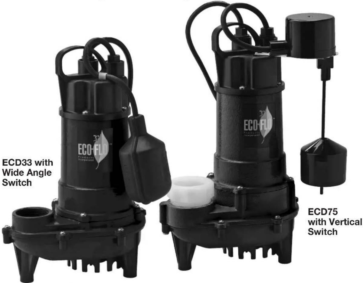
TABLE OF CONTENTS
General Safety 2
Specifications....3
Installation. 4 & 5
Troubleshooting 6
Warranty 7

Before you start
A sump pump is an electrical device designed to operate in inherently wet environments.
ALWAYS USE EXTREME CAUTION
when installing or maintaining this product!
Need Help: Call 1-877-326-3561 for assistance;
Do Not Return to Store
GENERAL SAFETY
Important Safety Instructions
Carefully read and follow all safety instructions in this manual and on pump.
SAVE THESE INSTRUCTIONS – This manual contains important instructions that should be followed during installation, operation, and maintenance of the product.
Save this manual for future reference.
Safety Labels
This is the safety alert symbol. When you see this symbol on your pump or in this manual, look for one of the following signal words and be alert to the potential for personal injury!

rd which, if
not avoided, will result in death or serious injury.

rd which,
if not avoided, could result in death or serious injury.

rd which, if
not avoided, could result in minor or moderate injury.
NOTICE indicates practices not related to personal injury.
Keep safety labels in good condition. Replace missing or damaged safety labels.
General Safety
A CAUTION Do not
touch an operating motor. Motors are designed to operate at high temperatures. To avoid burns when servicing pump, allow it to cool for 20 minutes after shut-down before handling.
Do not allow pump or any system component to freeze. To do so will void warranty.
Pump water only with this pump.
Periodically inspect pump and system components.
Wear safety glasses at all times when working on pumps.
A WARNING Risk of explosion. Pump
body may explode if used as a booster pump.
For parts or assistance, call ECO-FLO Customer Service at 1-877 326-3561
APPLICATIONS
Ideal for High-Volume Water Removal from Basement Sump Pits and Window Wells
SPECIFICATIONS & PERFORMANCE
| Model | HP | Volt | Ph | Amps | Capacity (GPH at 0') | Max Head | Construction | Impeller | Cord Length | Solids Pumped |
| ECD30W | 1/4 | 115 | 1 | 3.5 | 2700 | 23' | Cast Iron | Thermoplastic | 8' | 1/2" |
| ECD30V | 1/4 | 115 | 1 | 3.5 | 2700 | 23' | Cast Iron | Thermoplastic | 8' | 1/2" |
| ECD33W | 1/3 | 115 | 1 | 5.0 | 3300 | 31' | Cast Iron | Thermoplastic | 8' | 1/2" |
| ECD33V | 1/3 | 115 | 1 | 5.0 | 3300 | 31' | Cast Iron | Thermoplastic | 8' | 1/2" |
| ECD50W | 1/2 | 115 | 1 | 8.0 | 4000 | 27' | Cast Iron | Thermoplastic | 8' | 1/2" |
| ECD50V | 1/2 | 115 | 1 | 8.0 | 4400 | 27' | Cast Iron | Thermoplastic | 8' | 1/2" |
| ECD75W* | 3/4 | 115 | 1 | 8.0 | 6000 | 34' | Cast Iron | Thermoplastic | 8' | 3/4" |
| ECD75W* | 3/4 | 115 | 1 | 8.0 | 6000 | 34' | Cast Iron | Thermoplastic | 8' | 3/4" |
* 2" MNPT x 1-1/2" FNPT Adapter included
![ECD30/33/50 327.8 [12.92] 221.8[8.73] SWITCH OFF 401.8[15.82] SWITCH ON Ø234 [09.22]](/content/2026/04/641808/images/2d833257e10a52e2ecda9a771d851778cfd7e6a105b4dcc24c066e3bf93621c4.jpg)
![ECD75 357.8 [14.10] 251.8[9.91] SWITCH OFF 431.8[17.0] SWITCH ON Ø234 [Ø9.22]](/content/2026/04/641808/images/5925b29accc321c28f25e06e5f633f351cf569e5d3cd5826b940c40a898da999.jpg)
For parts or assistance, call ECO-FLO Customer Service at 1-877 326-3561
INSTALLATION

Do not work on pump until
power is unplugged.

use an adapter fitting.
Do not use an extension cord.
The pump power cord should be connected to a separately fused, grounded line with a minimum capacity of 15 amps. It can be connected to non-fuse breaker at the recommended amperes.
- Before installing or servicing this pump, be certain pump's power source is disconnected.
- Installation and electrical wiring must adhere to state and local codes and must be completed before priming pump. Check appropriate community agencies, or contact local electrical and pump professionals.
- Call an electrician when in doubt. Pump should be connected to a separate 15 amp circuit breaker or 15 amp fuse block.
Note that plugging into existing outlets may cause low voltage at motor. This could cause blown fuses, tripping of motor overload or burned out motor.
- A permanent ground connection from pump to the grounding bar at the service panel is mandatory. These sump pumps come with a grounding conductor and a grounding-type attachment plug. Do not connect pump to a power supply until permanently grounded.
For maximum safety, connect pump to a circuit equipped with a fault interrupter device when positioning the pump's grounding wire.
-
Voltage of power supply must match the voltage of the pump.
-
Before installing pump, clear sump basin of any water, debris or sediment.

plumbing codes. These Sump pumps are not designed for and CANNOT be installed in locations classified as hazardous.
- The following may cause injury and/or severe damage to pump and will void the warranty.
(a) Using an extension cord.
(b) Cutting off the ground pin or using an adapter fitting.
(c) Working on pump or switch while plugged in.
(d) Removing motor housing, unscrewing impeller, or otherwise removing impeller seal.
(e) Running the pump continuously.
(f) Pumping chemicals or corrosive liquids.
(g) Pumping gasoline or other flammable liquids
- Plastic PVC pipe can be installed in the outlet piping. Drain hose, galvanized steel or copper pipe may be used if desired. All piping must be clean and free of all foreign matter to prevent clogging.
- Pump will be inadequate if suspension liquids contain solid particles larger than 1/2" (3/4" ECD75).
ELECTRICAL WIRE CONNECTION

Verify that the voltage and frequency of the pump shown
on the nameplate corresponds to those available on the mains. The installer must make sure that the electric system is grounded in accordance with code.
- For outdoor use it is necessary to use cable with a length of 'at least 8'. The plug and connection should be protected from water splashes. Before using the pump, always inspect it visually (especially power cable and plug)
- Do not use pump if it is damaged
- If the pump is damaged, have it inspected by an authorized service center.
- Make sure that electric connections are protected from flooding. Protect the plug and the power cable from heat or sharp edges.

The power cable must be replaced by qualified personnel
only. Grounding: The plug of the power cable has a double grounding contact, so that grounding can be performed by simply inserting the plug.
OVERLOAD PROTECTION
This pump series has a built in thermal protection switch. The pump stops if an overload condition occurs. The motor restarts automatically after it has cooled down. If it doesn't start automatically, unplug the pump and plug it back in.
INSTALLATION
Discharge piping can be PVC, polypipe or galvanized steel.
CAUTION:
Check local codes before installing pump.
STEP 1:
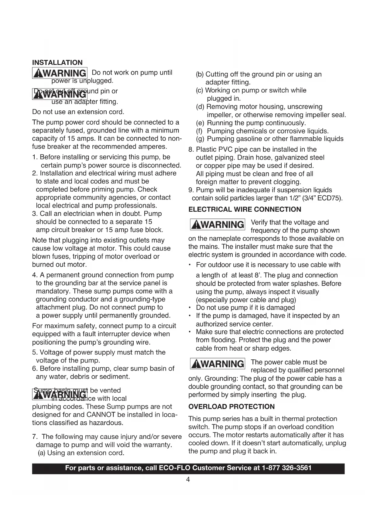
Pump must be installed in a suitable gas tight, properly vented basin which is at least 24" deep and is at least 18" wide for pumps fitted with wide angle on/off switches and at least 14" wide for pumps fitted with vertical on/off switches.
STEP 2:
Pump must be placed on a hard surface in a sump that has been cleared of all debris. Never place the pump on clay, earth or gravel surfaces and it is suggested the pump be placed on two bricks approximately 2" apart.
STEP 3:
Connect the discharge pipe, fittings and check valve to the discharge port of the pump. It is recommended that the discharge pipe diameter be equal to or larger than the discharge size of the pump.
TROUBLESHOOTING CHECKLIST (Caution: shut off power to pump)
| PROBLEMS | POSSIBLE CAUSES/SOLUTIONS |
| PUMP DOES NOT RUN AND MAKES HUMMING SOUND | Line circuit breaker is off, or fuse is blown or looseWater level in sump has not reached turn-on level as indicated in installation drawing.Pump cord is not making contact in receptacle.Float is stuck. It should operate freely in basin.If all of the above are OK, then the motor could be malfunctioning. |
| PUMP RUNS BUT DOES NOT DELIVER WATER | Check if valve is installed backwards.Arrow on valve should point direction of flowDischarge shut-off valve (if used) may be closed.Impeller or volute openings are fully or partially clogged.Remove pump and clean.Pump is air-locked. Start and stop several times by plugging and unplugging cord. Check for clogged vent hole in pump case.Inlet holes in pump base are clogged. Remove pump and clean the openings.Vertical pumping distance is too high. Reduce distance or change the discharge fittings of the pump. |
| PUMP RUNS AND PUMPS OUT SUMP, BUT DOES NOT STOP | Float is stuck in up position. Be sure float operates freely in basin.Defective float switch. Replace float switch. |
| PUMP RUNS BUT ONLY DELIVERS A SMALL AMOUNT OF WATER | Pump is air-locked. Start and stop several times by plugging in and unplugging cord. Check for clogged vent hole in pump case.Vertical pumping distance is too high. Reduce distance or change the discharge fitting of the pump. Inlet holes in pump base are clogged.Remove pump and clean the strainer and openings.Impeller or volute openings are fully or partially clogged.Remove pump and clean.Pump impeller is partially clogged with tar or paint, causing motor to run slow and overload. Remove pump and clean. |
| FUSE BLOWS OR CIRCUIT BREAKER TRIPS WHEN PUMP STARTS | Pump impeller is partially clogged causing motor to run slow and overload. Remove pump and clean.Motor stator may be defective.Fuse size or circuit breaker may be too small. (must be 15 amps).Impeller or volute opening are fully or partially clogged.Remove pump and clean . |
| MOTOR RUNS FOR A SHORT TIME, THEN STOPS | Inlet holes in pump base are clogged. Remove pump and clean the openings.Pump impeller is partially clogged causing motor to run slow and overload. Remove pump and clean.Motor stator may be defective.Impeller or volute openings are fully or partially clogged.Remove pump and clean. Also clean the strainer if one is installed. |
ELECTRICAL PRECAUTIONS

Before servicing a pump, always shut off the main power breaker and then unplug the pump. Make sure you are not standing in water and are
wearing insulated protective sole shoes, under flooded conditions. Contact your local electric company or a qualified licensed electrician for disconnecting electrical service prior to pump removal
For parts or assistance, call ECO-FLO Customer Service at 1-877 326-3561
WARRANTY
Retain Original Purchase Receipt for Warranty Eligibility
Limited Warranty
Manufacturer warrants to the original consumer purchaser (“Purchaser” or “You”) that its products are free from defects in material and workmanship for a period of twenty-four (24) months from the date of the original consumer purchase. If, within twenty-four (24) months from the original consumer purchase, any such product shall prove to be defective, it shall be repaired or replaced at manufacturer’s option, subject to the terms and conditions set forth herein. Note that this limited warranty applies to manufacturing defects only and not to ordinary wear and tear. All mechanical devices need periodic parts and service to perform well. This limited warranty does not cover repair when normal use has exhausted the life of a part or the equipment.
The original purchase receipt and product warranty information label are required to determine warranty eligibility. Eligibility is based on purchase date or original product – not the date of replacement under warranty. The warranty is limited to repair or replacement of original purchased product only, not replacement product (i.e. one warranty replacement allowed per purchase).
Purchaser pays all removal, installation, labor, shipping, and incidental charges.
Claims made under this warranty shall be made by returning the product to the retail outlet where it was purchased or to the factory immediately after the discovery or any alleged defect. Manufacturer will subsequently take corrective action as promptly as reasonably possible. No requests for service will be accepted if received more than 30 days after the warranty expires. Warranty is not transferable and does not apply to products used in commercial/rental applications.
General Terms and Conditions; Limitations of Remedies
You must pay all labor and shipping charges necessary to replace product covered by this warranty. This warranty does not apply to the following: (1) acts of God; (2) products which, in manufacturer's sole judgment, have been subject to negligence, abuse, accident, misapplication, tampering, or alteration; (3) failures due to improper installation, operation, maintenance or storage; (4) atypical or unapproved application, use or service; (5) failures caused by corrosion, rust or other foreign materials in the system, or operation at pressures in excess of recommended maximums.
This warranty sets forth manufacturer's sole obligation and purchaser's exclusive remedy for defective products.
MANUFACTURER SHALL NOT BE LIABLE FOR ANY CONSEQUENTIAL, INCIDENTAL, OR CONTINGENT DAMAGES WHATSOEVER. THE FOREGOING LIMITED WARRANTIES ARE EXCLUSIVE AND IN LIEU OF ALL OTHER EXPRESS AND IMPLIED WARRANTIES, INCLUDING BUT NOT LIMITED TO IMPLIED WARRANTIES OF MERCHANTABILITY AND FITNESS FOR A PARTICULAR PURPOSE. THE FOREGOING LIMITED WARRANTIES SHALL NOT EXTEND BEYOND THE DURATION PROVIDED HEREIN.
Some states do not allow the exclusion or limitation of incidental or consequential damages or limitations on how long an implied warranty lasts, so the above limitations or exclusions may not apply to You. This warranty gives You specific legal rights and You may also have other rights which vary from state to state.

1899 Cottage Street, Ashland, Ohio 44805
Telephone: 1-877-326-3561
Fax: 1-877-326-1994
www.ecofloproducts.com

Installation....11 - 12
Dépannage. 13
Garantie. 14

not avoided, will result in death or serious injury.
![ECD75 357.8 [14.10] 251.8[9.91] SWITCH OFF 431.8[17.0] SWITCH ON Ø234 [Ø9.22]](/content/2026/04/641808/images/93101a6fede5a24b3edaad89b459b142e1798ec504653456f986d0071ce6a324.jpg)
1899 Cottage Street, Ashland, Ohio 44805
Téléphonez: 1-877-326-3561
Fax: 1-877-326-1994
www.ecofloproducts.com

![ECD75 357.8 [14.10] 251.8[9.9] SWITCH OFF 431.8[17.0] SWITCH ON Ø234 [09.22]](/content/2026/04/641808/images/1a7f6a3766abc9fa8bc6ad3cdf89ddd036789e1c58d5002c37099f46ee557aee.jpg)
1899 Cottage Street, Ashland, Ohio 44805
Copyright © 2014, ECO-FLO PRODUCTS, INC.
EF-SPPOM-116-1114