Plastic Shallow Jet Pump - Pump Eco-Flo - Free user manual and instructions
Find the device manual for free Plastic Shallow Jet Pump Eco-Flo in PDF.

User questions about Plastic Shallow Jet Pump Eco-Flo
0 question about this device. Answer the ones you know or ask your own.
Ask a new question about this device
Download the instructions for your Pump in PDF format for free! Find your manual Plastic Shallow Jet Pump - Eco-Flo and take your electronic device back in hand. On this page are published all the documents necessary for the use of your device. Plastic Shallow Jet Pump by Eco-Flo.
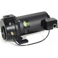
USER MANUAL Plastic Shallow Jet Pump Eco-Flo
Owner's Manual Plastic Shallow Jet Pumps
natural_image
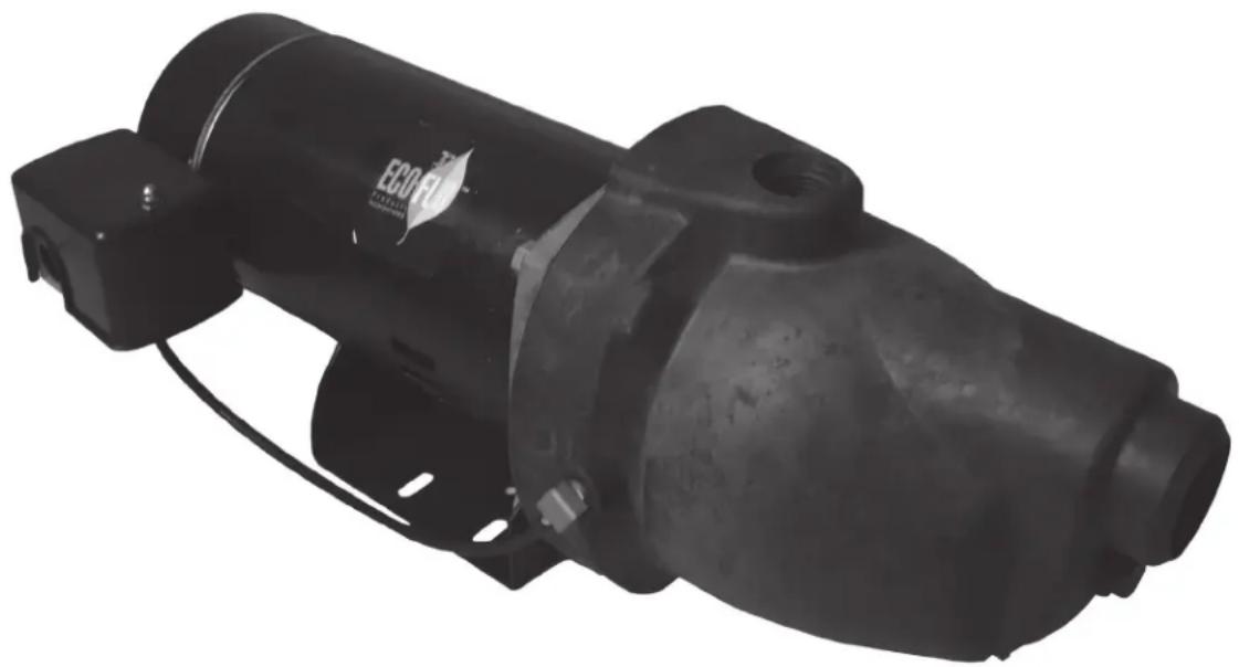
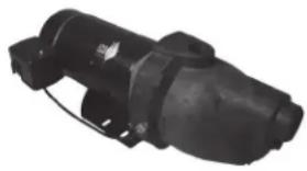
Black industrial electric motor with attached power outlet and mounting bracket (no visible text or symbols)TABLE OF CONTENTS
General Safety 2
Installation 3-5
Electrical 6
Operation 7
Troubleshooting 8
Repair Parts 9
Jet/Tank Assembly 10
Warranty 11

Before you start
Safety: Need safety Info
- Avoid Pressure Burns/Explosion
- Avoid Electric Shock
Fill Pump with water: Ensure pump body is filled with water to discharge.
Motor's Electrical Settings: Set motor to proper voltage, i.e. voltage supplied to pump – See electrical section
Need Help: Call 1-877-326-3561 for assistance
GENERAL SAFETY
Important Safety Instructions Safety Labels Carefully read and follow all safety instructions in this manual and on pump.
SAVE THESE INSTRUCTIONS – This manual contains important instructions that should be followed during installation, operation, and maintenance of the product. Save this manual for future reference.
This is the safety alert symbol. When you see this symbol on your pump or in this manual, look for one of the following signal words and be alert to the potential for personal injury!

rd which, if
not avoided, will result in death or serious injury.

rd which,
if not avoided, could result in death or serious injury.

rd which, if
not avoided, could result in minor or moderate injury.
NOTICE indicates practices not related to personal injury.
Keep safety labels in good condition. Replace missing or damaged safety labels.
General Safety
Risk of burns. Do not
touch an operating motor. Motors are designed to operate at high temperatures. To avoid burns when servicing pump, allow it to cool for 20 minutes after shut-down before handling.
Do not allow pump or any system component to freeze. To do so will void warranty.
Pump water only with this pump.
Periodically inspect pump and system components.
Wear safety glasses at all times when working on pumps.

n. Pump
body may explode if used as a booster pump.
REPLACING AN OLD PUMP
WARNING
Disconnect power to pump before
working on pump or motor.
- Drain and remove the old pump. Check the old pipe for scale, lime, rust, etc., and replace it if necessary.
- Install the pump in the system. Make sure that all pipe joints in the suction pipe are air-tight as well as water
tight. If the suction pipe can suck air, the pump will not be able to pull water from the well.
- Adjust the pump mounting height so that the plumbing connections do not put a strain on the pump body. Support the pipe so that the pump body does not take the weight of piping or fittings.
DEDICATED SHALLOW WELL PUMP INSTALLATIONS
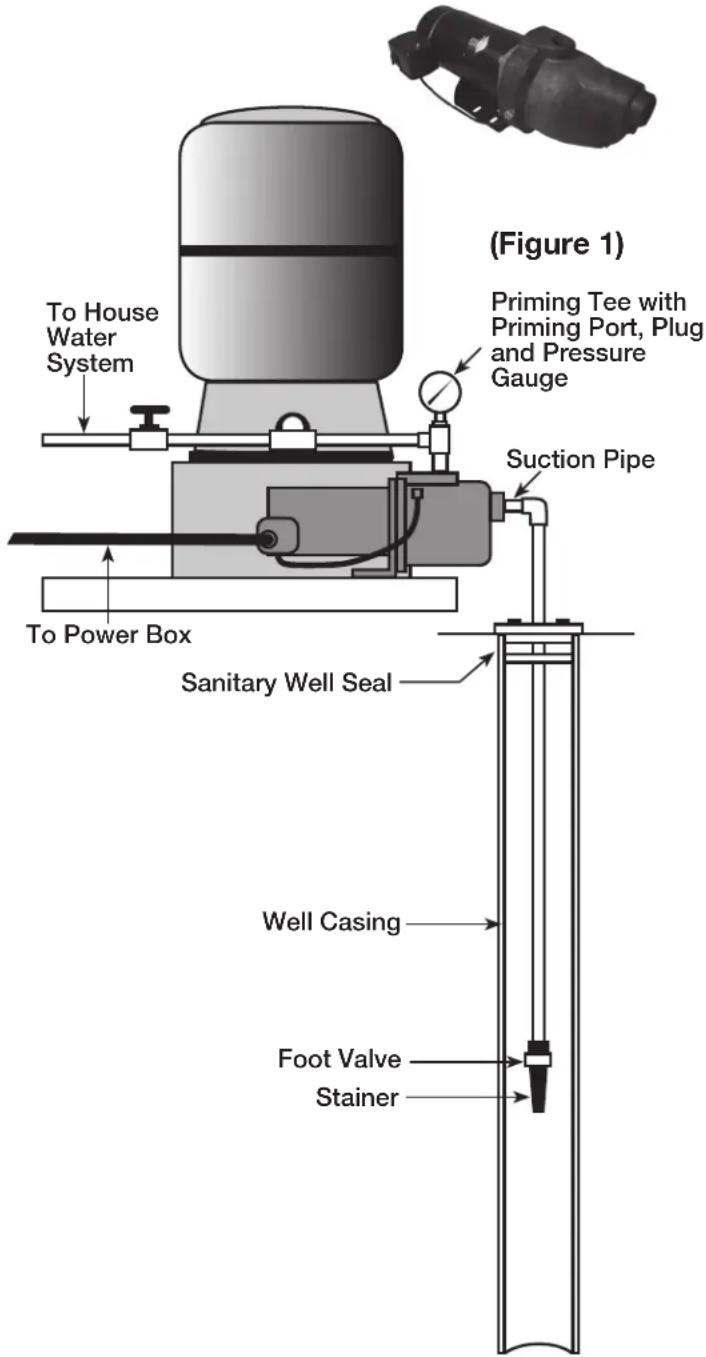
Cased Well Installation (Figure 1)
- Mount the pump as close to the well as possible.
- Assemble the foot valve, strainer, and well pipe. Make sure that the foot valve works freely.
- Lower the pipe into the well until the strainer is five feet above the bottom of the well. It should also be at least 10 feet below the well's water level.
- Install a sanitary well seal.
- Install a priming tee, priming plug, and pressure gauge to pump's discharge port. Connect the pipe from the well to the pump's suction port, using the fewest possible fittings-especially elbows – increase friction in the pipe. The suction pipe should be at least as large as the suction port on the pump. Support the pipe so that there are no dips or sags in the pipe, so not to strain the pump body, and so that it slopes slightly upward from the well to the pump (Note: Not doing so can create air locks preventing the pump from working properly). Seal the suction pipe joints with PTFE pipe thread sealant tape or a PTFE-based pipe joint compound. Joints must be air-and-water-tight. If the suction pipe can suck air, the pump cannot pull water from well.
- See instructions on page 8 for connecting discharge pipe to tank.
For parts or assistance, call ECO-FLO Customer Service at 1-877 326-3561
DEDICATED SHALLOW WELL PUMP INSTALLATIONS
Driven Point Installation (Figure 2)
- Drive the well point, using "drive couplings" and a "drivecap". "Drive fittings" are threaded all the way through and allow the pipe ends to butt against each other so that the driving force of the maul is carried by the pipe and not by the threads. The ordinary fittings found in hardware stores are not threaded all the way through the fitting and can collapse under impact. "Drive fittings" are also smoother than standard plumbing fittings, making ground penetration easier.
- Mount the pump as close to the well as possible.
- Use the fewest possible fittings (especially elbows) when connecting the pipe from the well point to the pump suction port. The suction pipe should be at least as large as the suction port on the pump.
- Install a check valve if your pump is not equipped with one.
- Install a priming tee, priming plug, and pressure gauge to pump's discharge port. Connect the pipe from the well to the pump's suction port, using the fewest possible fittings-especially elbows – increase friction in the pipe. The suction pipe should be at least as large as the suction port on the pump. Support the pipe so that there are no dips or sags in the pipe, so not to strain the pump body, and so that it slopes slightly upward from the well to the pump (Note: Not doing so can create air locks preventing the pump from working properly). Seal the suction pipe joints with PTFE pipe thread sealant tape or a PTFE-based pipe joint compound. Joints must be air-and-water-tight. If the suction pipe can suck air, the pump cannot pull water from well.
- If one well point does not supply enough water, consider connecting two or three well points to one suction pipe.
- See instructions on page 8 for connecting discharge pipe to tank.
natural_image
Black industrial electrical component with no visible text or symbols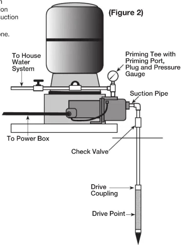
DEDICATED SHALLOW WELL PUMP INSTALLATIONS
Surface Water Installation (Figure 3)
Possible contamination. Do not use surface water for drinking. The installation shown could be used for sprinkler applications.
- The pump should be installed as close to the water as possible, with the fewest possible fittings (especially elbows) in the suction pipe. The suction pipe should be at least as large as the suction port on the pump.
- Assemble a foot valve and strainer to the suction pipe. Make sure that the foot valve works freely. Use PTFE pipe thread sealant tape or a PTFE-based pipe joint compound on threaded pipe joints.
- Install a screen to protect the water system from letting debris enter the system.
- Lower the pipe into the water until the strainer is five feet above the bottom. It should also be at least 10 feet below the water level in order to prevent the pump from sucking air.
- Install a priming tee, priming plug, and pressure gauge to pump's discharge port. Connect the pipe from the well to the pump's suction port, using the fewest possible fittings-especially elbows – increase friction in the pipe. The suction pipe should be at least as large as the suction port on the pump. Support the pipe so that there are no dips or sags in the pipe, so not to strain the pump body, and so that it slopes slightly upward from the well to the pump (Note: Not doing so can create air locks preventing the pump from working properly). Seal the suction pipe joints with PTFE pipe thread sealant tape or a PTFE-based pipe joint compound. Joints must be air-and-water-tight. If the suction pipe can suck air, the pump cannot pull water from well.
- Joints must be air-and water-tight. If the suction pipe can suck air, the pump cannot pull water from the water source.
- See instructions on page 8 for connecting discharge pipe to tank.
natural_image
Black industrial electrical component with no visible text or symbols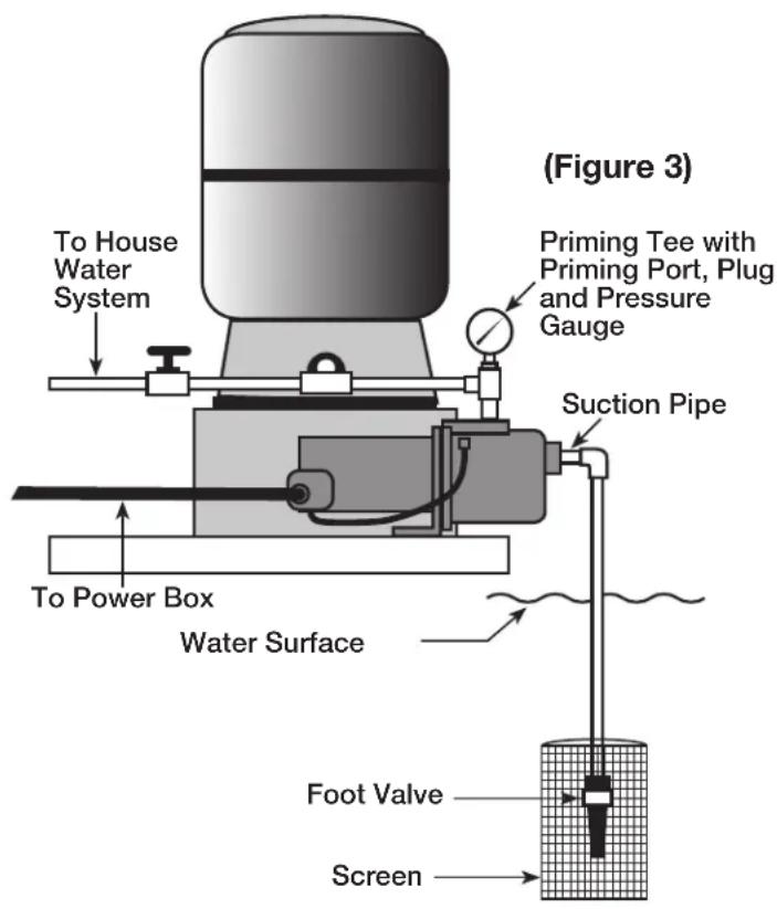
ELECTRICAL

Disconnect power before working on pump, motor, pressure switch or wiring

CAUTION
Motor may be hot. Allow to cool 20 minutes.

CAUTION
Water pressure may have built up in the pump, pipes and/or tank. Drain water to relieve pressure.
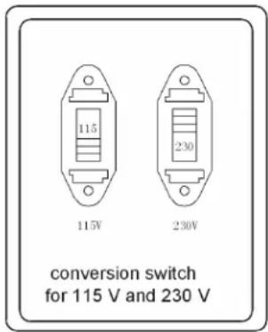
Motor Switch Settings (Figure 8)
Motors are designed to run on either 115 volt or 230 volt current. Be sure the motor's wires are attached properly to the motor's control panel for the voltage required.
Wiring Pressure Switch
Attach the wires from the power source to the pressure switch following the directions provided under the cover of the pressure switch, i.e. remove the pressure switch cover and follow wiring directions under the cover lid. Be sure to ground wire the pressure switch to the motor.
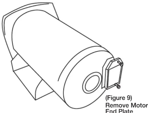
Wiring the Motor (Figure 9)
Attach wires between the pressure switch and the motor ensuring the wires are connected to the motor for the proper electrical source voltage, i.e. 115V or 230V- see the wiring diagrams in this manual or under the cover of the motor. Ensure to ground the pressure switch to the motor.
Wiring

Risk of electric shock.
Can shock, burn or kill.
- To avoid dangerous or fatal electrical shock, turn OFF power to motor before working on electrical connections.
- Ground motor before connecting to electrical power supply. Failure to ground motor can cause severe or fatal electrical shock hazard.
- Supply voltage must be within +/- 10% of nameplate voltage. Incorrect voltage can cause fire or damage motor and voids warranty. If in doubt consult a licensed electrician.
Figure 8
- Use wire size specified in Wiring Chart (below). If possible, connect pump to a separate branch circuit with no other appliances on it.
- Do not ground to a gas supply line.
- Wire motor according to diagram on motor nameplate. If nameplate diagram differs from diagrams above, follow nameplate diagram.
- If this procedure or the wiring diagrams are confusing, consult a licensed electrician.
Wiring Chart Recommended Wire and Fuse Sizes for 115 and 230 volts
| MOTOR HP | VOLTS | MAX. LOAD AMP RATING | BRANCH FUSE AMP SIZE (mm ^2 ) | AWG MIN. WIRE 0- | DISTANCE IN FEET FROM MOTOR TO SUPPLY | ||||
| 100 101-200 | 201-300 30 | 1-400 401-500 | 0 | ||||||
| AWG WIRE SIZE (mm ^2 ) | |||||||||
| 1/2 | 115/230 | 10.6/6.5 | 15/15 | 12/14 (3/2) | 12/14 (8.4/2) | 8/14 (2/2) | 6/14 (14/2) | 6/12 (14/3) | 4/10 (21/5.5) |
| 3/4 | 115/230 | 11/6.6 | 20/15 | 10/14 (5.5/2) | 12/14 (8.4/2) | 8/14 (8.4/2) | 6/12 (14/3) | 4/10 (21/5.5) | 4/10 (21/5.5) |
| 1 | 115/230 | 11.8/6.7 | 25/15 | 10/14 (5.5/2) | 6/14 (14/2) | 8/14 (8.4/2) | 6/12 (14/3) | 4/10 (21/5.5) | 4/10 (21/5.5) |
For parts or assistance, call ECO-FLO Customer Service at 1-877 326-3561
OPERATION

WARNING
Hazardous Pressure,
Install pressure relief valve in discharge pipe.
Release all pressure on system before working on any component.
PREPARING TO START THE PUMP - SHALLOW WELL
WARNING burns. Never run pump dry. Running pump without water may cause pump to overheat, damaging seal and possibly causing burns to persons handling pump. Fill pump with water before starting.
CAUTION
Be sure the pump is full of water before starting the motor.
WARNING Risk of explosion and scalding. Never run pump against closed discharge. To do so can boil water inside pump, causing hazardous pressure in unit, risk of explosion and possible scalding persons handling pump.
-
Open the control valve as far as possible. Then remove the priming plug from the pump and fill the pump, fill all piping between the pump and the well, and make sure that all piping in the well is full. If you have also installed a priming tee in the suction piping, remove the plug from the tee and fill the suction piping.
-
Replace all fill plugs. Leave the control valve open (in a shallow well installation, the control valve always stays open).
-
Turn electric power on!
-
Start the pump. The pump should pump water in two or three minutes.
-
If you don't have water after 2 or 3 minutes, stop the pump and remove the fill plugs. Refill the pump and piping. You may have to repeat this two or three times in order to get all the trapped air out of the piping. The control valve remains open throughout this procedure.
-
After the pump has built up pressure in the system and shut off, check the pressure switch operation by opening a faucet or two and running enough water out to bleed off pressure until the pump starts. If your jet has a 30/50 pressure switch, the pump should start when the pressure drops to 30 PSI and stop when pressure reaches 50 PSI. Run the pump through one or two complete cycles to verify correct operation. This will also help clean the system of dirt and scale dislodged during installation.
PREPARING TO START THE PUMP - DEEP WELL
WARNING Risk of burns. Never run pump dry. Running pump without water may cause pump to overheat, damaging seal and possibly causing burns to persons handling pump. Fill pump with water before starting.
CAUTION
Be sure the pump is full of water before starting the motor.
⚠ WARNING Risk of explosion and scalding. Never run pump against closed discharge. To do so can boil water inside pump, causing hazardous pressure in unit, risk of explosion and possibly scalding persons handling pump.
-
Open the pressure regulator control valve as far as possible. Then remove the priming plug from the pump and fill the pump, fill all piping between the pump and the well, and make sure that all piping in the well is full. If you have also installed a priming tee in the suction piping, remove the plug from the tee and fill the suction piping.
-
Replace all plugs.
-
Power on!
-
Start the pump and watch the pressure gauge. The pressure should build rapidly to 50 PSI as the pump primes.
-
Open several faucets in the residence to permit water flow and to release trapped air. After 2 or 3 minutes, the gauge should show pressure. If not, stop the pump,
remove the fill plugs, and refill the pump and piping. You may have to repeat this two or three times in order to get all the trapped air out of the piping.
-
When water pressure has built up and is maintained by the pump, slowly close the pressure regulator control valve while watching the pressure gauge needle. Continue closing the valve until you see the pressure gauge needle start to flutter. If the needle starts to flutter, slowly open the valve just enough to stop the flutter. Your pump is now operating at peak efficiency.
-
Close all open faucets. After the pump has built up pressure in the system and shut off, check the pressure switch operation by opening a faucet or two and running enough water out to bleed off pressure until the pump starts. If your jet has a 30/50 pressure switch, the pump should start when the pressure drops to 30 PSI and stop when pressure reaches 50 PSI. Run the pump through one or two complete cycles to verify correct operation. This will also help clean the system of dirt and scale dislodged during installation.
For parts or assistance, call ECO-FLO Customer Service at 1-877 326-3561
TROUBLE SHOOTING
| SYSTEM | POSSIBLE CAUSE(S) | |
| Motor will not run | Fuse is blown or circuit breaker tripped | Replace fuse or reset circuit breaker. |
| Starting switch is defective | DISCONNECT POWER; Replace starting switch | |
| Wires at motor are loose, disconnected, or wired incorrectly | Refer to instructions on wiring (Page 9). DISCONNECT POWER; check and tighten all wiring. (WARNING symbol) Hazardous voltage. Capacitor voltage may be hazardous. To discharge capacitor, hold insulated handle screwdriver BY THE HANDLE and short capacitor terminals together. Do not touch metal screwdriver blade or capacitor terminals. If in doubt, consult a qualified electrician. | |
| Motor runs hot and overload kicks off | Motor is wired incorrectly | Refer to instructions on wiring. |
| Voltage is too low | Check with power company. Install heavier wiring if wire size is too small (See Electrical/Wiring Chart) | |
| Pump cycles too frequently | See section below on too frequent cycling. | |
| Motor runs but no water is delivered* | Pump in new installation did not prime due to:1. Pipes were not filled with water2. Air leaks3. Leaking foot valve or check valve | In new installation:1. Re-prime according to instructions.2. Check all connections on suction line and AVC with shaving cream.3. Replace foot valve or check valve. |
| Pump has lost prime through:1. Air leaks2. Water level below suction pipe inlet3. Faulty check or foot valve. | In installation already in use:1. Check all connections on suction line and shaft seal.2. Lower suction line into water and re-prime. If receding water level in well exceeds 25' (7.6M0, a deep well pump is needed.3. Replace faulty valve. | |
| Foot valve or strainer is plugged | Clean foot valve or strainer | |
| Ejector or impeller is plugged | Clean ejector or impeller. | |
| Check valve or foot valve is stuck shut | Replace check valve or foot valve. | |
| Pipes are frozen | Thaw pipes. Bury pipes below frost line. Heat pit or pump house. | |
| Foot valve and/or strainer are buried in sand or mud | Raise foot valve and/or strainer above bottom of water source. Clean foot valve and strainer. | |
| Water level is too low for shallow well setup to deliver water | A deep well jet will be needed if your well is more than 25' (7.6M0 depth to water. | |
| Pump does not deliver water to full capacity (Also check point 3 immediately above) | Water level in well is lower than estimated. | A new nozzle and venturi combination may be needed. |
| Steel piping (if used) is corroded or limed, causing excess friction | Replace with plastic pipe where possible, otherwise with new steel pipe. | |
| Piping is too small in size | Use larger piping. | |
| Pump delivers water but does not shut off or pump cycles too frequently | Pressure switch is out of adjustment or contacts are welded together | DISCONNECT POWER; adjust or replace pressure switch |
| Faucets have been left open | Close faucets | |
| Venturi, nozzle or impeller is clogged | Clean venturi, nozzle or impeller | |
| Standard pressure tank is waterlogged and has no air cushion | Drain tank to air volume control port. Check AVC for defects. Check all connections for leaks. | |
| Pipes leak | Check connections. | |
| Foot valve leaks | Replace foot valve. | |
| Pressure switch is out of adjustment | Adjust or replace pressure switch. | |
| Air charge too low in pre-charged tank | DISCONNECT POWER and open faucets until all pressure is relieved. Using tire pressure gauge, check air pressure in tank at valve stem located on the tank. If less than pressure switch cut in setting (30-50 PSI), pump air into tank from outside source until air pressure is 2 PSI less than cut-in setting of switch. Check air valve for leaks (use soapy solution) and replace core if necessary. | |
| Air spurts from faucets | Pump is not primed | When pump has picked up prime, it should pump solid water with no air. |
| Leak in suction side of pump | Suction pipe is sucking air. Check joints for leaks with shaving cream. | |
| Well is gaseous | Consult factory about installing a sleeve in the well. | |
| Intermittent over-pumping of well. (Water drawn down below foot valve.) | Lower foot valve if possible, otherwise restrict pump discharge. | |
For parts or assistance, call ECO-FLO Customer Service at 1-877 326-3561
SHALLOW WELL PUMP REPAIR PARTS
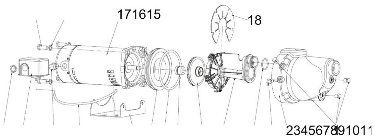
| NO. | QUANTITY | PART NUMBER | DESCRIPTION |
| 1 | 3 | EFSWJ5P01 | Plug |
| 2 | 1 | EFSWJ5P02 | Volute |
| 3 | 1 | EFSWJ5P03 | Adapter/Pressure Switch |
| 4 | 1 | EFSWJ5P04 | O-Ring |
| 5 | 1 | EFSWJ5P05 | Diffuser for 1/2 HP |
| 1 | EFSWJ7P05 | Diffuser for 3/4 HP | |
| 1 | EFSWJ7P05 | Diffuser for 1 HP | |
| 6 | 1 | EFSWJ5P06 | Impeller for 1/2 HP |
| 1 | EFSWJ7P06 | Impeller for 3/4 HP | |
| 1 | EFSWJ7P06 | Impeller for 1 HP | |
| 7 | 1 | EFSWJ5P07 | Seal |
| 8 | 1 | EFSWJ5P08 | O-Ring |
| 9 | 1 | EFSWJ5P09 | Seal Plate |
| 10 | 1 | EFSWJ5P10 | Base |
| 11 | 1 | EFSWJ5P11 | Pressure Tube |
| 12 | 1 | EFSWJ5P12 | Adaptor |
| 13 | 1 | EFSWJ5P13 | Pressure Switch |
| 14 | 1 | EFSWJ5P14 | Nut |
| 15 | 4 | EFSWJ5P15 | Screw |
| 16 | 4 | EFSWJ5P16 | Washer |
| 17 | 1 | EFSWJ5P17 | Motor for 1/2 HP |
| 1 | EFSWJ7P17 | Motor for 3/4 HP | |
| 1 | EFSWJ1P17 | Motor for 1 HP | |
| 18 | 1 | EFSWJ5P18 | Plate |
For parts or assistance, call ECO-FLO Customer Service at 1-877 326-3561
JET/TANK PUMP ASSEMBLY
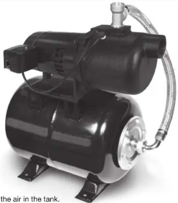
natural_image
Black industrial air compressor with coiled hose and valve, no visible text or symbols on device bodyTank
- Remove tank from its carton.
- Using a tire pressure gauge, check the air in the tank.
It may need to be adjusted once you know the on/off settings on the pump's pressure switch (see number 3 below).
Pump
- Remove the pump from its carton.
- Retain the pump's owners manual.
- Remove the cover from the pump's pressure switch, and read the on/off settings from the underside of the pressure switch cover. Typically readings are:
a. Pump (motor) on pressure: 30 PSI (pounds per square inch);
b. Pump (motor) off pressure: 50 PSI. - Once you know the turn on/off pressures, alter the air pressure in the empty pre-charge tank to 2 (two) PSI below the "on" pressure, i.e. to 28 PSI.
- It is critical the pressure in the tank be 2 PSI below the "tank turn" on pressure
Mounting Kit
- Remove the kit's contents and sort them into groups.
Jet Tank Assembly
- Mount the jet on to the tank securing the jet with the 4 bolts, washers, and nuts provided in the kit.
- Ensure the input end of the pump is on the same end of the tank input end.
- Snug the nuts on the bolts while you install other pieces of the kit.
- Use Teflon tape or other plumbing sealant to ensure all connections are sealed.
For parts or assistance, call ECO-FLO Customer Service at 1-877 326-3561
WARRANTY
Retain Original Purchase Receipt for Warranty Eligibility
Limited Warranty
Manufacturer warrants to the original consumer purchaser (“Purchaser” or “You”) that its products are free from defects in material and workmanship for a period of twelve (12) months from the date of the original consumer purchase. If, within twelve (12) months from the original consumer purchase, any such product shall prove to be defective, it shall be repaired or replaced at manufacturer’s option, subject to the terms and conditions set forth herein. Note that this limited warranty applies to manufacturing defects only and not to ordinary wear and tear. All mechanical devices need periodic parts and service to perform well. This limited warranty does not cover repair when normal use has exhausted the life of a part or the equipment.
The original purchase receipt and product warranty information label are required to determine warranty eligibility. Eligibility is based on purchase date or original product – not the date of replacement under warranty. The warranty is limited to repair or replacement of original purchased product only, not replacement product (i.e. one warranty replacement allowed per purchase).
Purchaser pays all removal, installation, labor, shipping, and incidental charges.
Claims made under this warranty shall be made by contacting and returning the product to the factory immediately after the discovery or any alleged defect. Manufacturer will subsequently take corrective action as promptly as reasonably possible. No requests for service will be accepted if received more than 30 days after the warranty expires. Warranty is not transferable and does not apply to products used in commercial/rental applications.
General Terms and Conditions; Limitations of Remedies
You must pay all labor and shipping charges necessary to replace product covered by this warranty. This warranty does not apply to the following: (1) acts of God; (2) products which, in manufacturer's sole judgment, have been subject to negligence, abuse, accident, misapplication, tampering, or alteration; (3) failures due to improper installation, operation, maintenance or storage; (4) atypical or unapproved application, use or service; (5) failures caused by corrosion, rust or other foreign materials in the system, or operation at pressures in excess of recommended maximums.
This warranty sets forth manufacturer's sole obligation and purchaser's exclusive remedy for defective products.
MANUFACTURER SHALL NOT BE LIABLE FOR ANY CONSEQUENTIAL, INCIDENTAL, OR CONTINGENT DAMAGES WHATSOEVER. THE FOREGOING LIMITED WARRANTIES ARE EXCLUSIVE AND IN LIEU OF ALL OTHER EXPRESS AND IMPLIED WARRANTIES, INCLUDING BUT NOT LIMITED TO IMPLIED WARRANTIES OF MERCHANTABILITY AND FITNESS FOR A PARTICULAR PURPOSE. THE FOREGOING LIMITED WARRANTIES SHALL NOT EXTEND BEYOND THE DURATION PROVIDED HEREIN.
Some states do not allow the exclusion or limitation of incidental or consequential damages or limitations on how long an implied warranty lasts, so the above limitations or exclusions may not apply to You. This warranty gives You specific legal rights and You may also have other rights which vary from state to state.

1899 Cottage Street, Ashland, Ohio 44805
Telephone: 1-877-326-3561
Fax: 1-877-326-1994
www.ecofloproducts.com
For parts or assistance, call ECO-FLO Customer Service at 1-877 326-3561
natural_image
Black industrial electric motor with attached terminal block (no visible text or symbols)Table des Matières
not avoided, will result in death or serious injury.

natural_image
Black industrial electrical connector with no visible text or symbols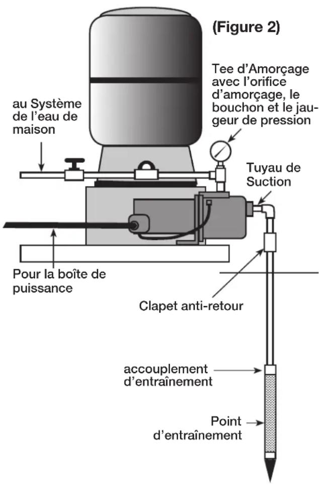
natural_image
Black industrial mechanical component with no visible text or symbols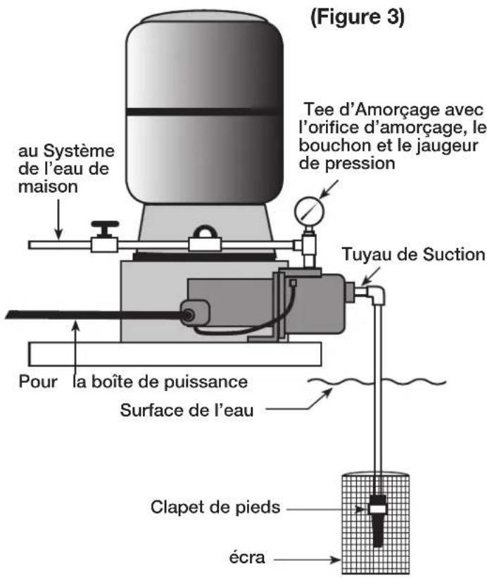
natural_image
Line drawing of a cylindrical mechanical component with mounting bracket (no text or symbols)natural_image
Black industrial air compressor with coiled tubing and mounting base (no visible text or symbols)LE RÉSERVOIR
1899 Cottage Street, Ashland, Ohio 44805
Téléphonez: 1-877-326-3561
Fax: 1-877-326-1994
www.ecofloproducts.com
Manual del usuario
natural_image
Black industrial electric motor with attached mounting bracket and mounting base (no visible text or symbols)Tabla de Contenido
natural_image
Black industrial electrical component with no visible text or symbols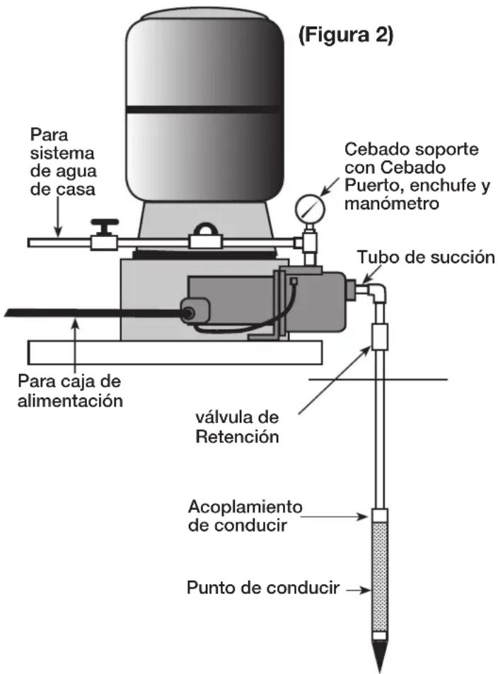
natural_image
Black industrial mechanical component with no visible text or symbols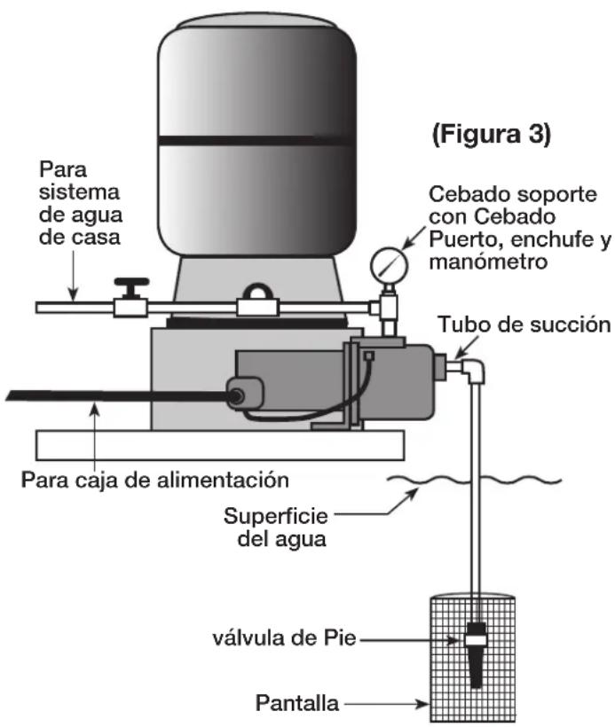
natural_image
Line drawing of a cylindrical mechanical component with mounting bracket, labeled (Figure 1) and 'Retire do ext' (no other text or symbols)(Figura 9) Retire Placa de extremo del Motor
natural_image
Black industrial air compressor with coiled tubing and mounting base (no visible text or symbols)Tanque
1899 Cottage Street, Ashland, Ohio 44805
Copyright © 2014, ECO-FLO PRODUCTS, INC.
EF-PJETOM-117-1114