USER MANUAL Zanotti Monoblock BSB0870Y1AA DAIKIN
CE
SB
natural_image
Illustration of a forklift and two industrial lifting devices (no text or symbols)
AVVERTENZE
natural_image
Illustration of a control panel connected to a yellow mechanical bracket (no text or symbols visible)
ATTENZIONE
AVVERTENZE
natural_image
Symbol of a trash bin crossed out by two crossed lines, representing no waste or discharge (no text or labels)
- Safety recommendations
- Table of warning and attention plates
- Description of the unit
- Operation
-
Handling
-
Installation
6.1 Plates
6.2 Dimensions
6.3 Location
6.4 Free room
6.5 Installation
6.6 Fitting the remote panel
6.7 Safety devices
6.8 Cleaning
- Connecting the unit
7.1 Electric connection
7.2 Connection to water system
- Electric controls
8.1 Control panel
- Checks, regulations and adjustments
9.1 Starting
9.2 How to Lock / Unlock the keyboard
-
Wiring
-
Maintenance and repairs
-
Routine maintenance
12.1 Periodical maintenance
12.2 Service operations to be carried out by qualified technicians or by the manufacturer
12.3 Troubleshooting
12.4 Alarms
-
How to order spare parts
-
How to dispose of the packing
-
How to dispose of the unit
Thank you for choosing Uniblock.
Please read these instructions carefully. They provide details and advice on the correct method of installing, using and maintaining this unit, in order to obtain maximum reliability, efficiency and long life.
1. SAFETY RECOMMENDATIONS
When installing and using the unit please follow the recommendations listed here below.
- Installation shall be carried out in strict compliance with the diagrams and instructions supplied by the manufacturer.
• Damages due to improper connections are excluded.
• The electric system available where the unit is installed shall meet the relevant standards in force.
- Maintenance shall be effected by trained personnel or by the manufacturer according to the provisions supplied by EN378.
WARNING
Use safety gloves to protect your hands from possible cuts.
The user is strongly recommended to contact the manufacturer before attempting any intervention on the unit and any use not corresponding to the manufacturer's indications (in particular as for the field of application) and to enquire about the possible dangers and contra-indications connected with an improper use of the machine.
- The unit shall be used following these instructions and sticking to the destination of use indicated by the supplier. Any incorrect use can result in damages to the unit and represents a serious danger for people's health.
ATTENTION
The unit is not suitable for working in explosive environments.
Therefore the use of the unit in an explosion-dangerous atmosphere is absolutely forbidden.

ATTENTION
The unit is not suitable for working in salty environments. In such a case protect condenser and evaporator with appropriate means.
When maintenance involves operations on the refrigerating circuit, empty the system and let it reach the atmospheric pressure.

WARNING
Do not discharge the refrigerant in the atmosphere. It must be recovered by specialized technicians using suitable equipment.
• Quantity and quality of the refrigerant to be charged are indicated on the data plate.
- Do not use refrigerants of different kind (especially inflammable fluids, for example hydrocarbons) or air.
- Do not modify or alter the refrigerating circuit or its components (for example: welding on compressor body)
- The final user shall protect the system from external fire dangers.
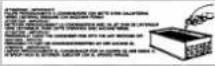
2. TABLE OF WATNING AND ATTENTION PLATES
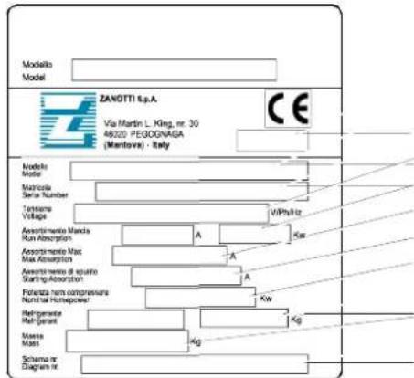
a) Year of manufacture
b) Zanotti unit code
c) Serial Number
d) Voltage
e) Run Absorption
f) Max Absorption
g) Starting Absorption
h) Compressor's nominal power
i) Refrigerant; Type; Quantity;
j) Mass of the unit
k) Electric diagram number
 | Refrigerant |
 | Condensate drain line |
 | Attention: hot or cold parts. |
 | Attention: switch off before operating on the unit. |
 | Attention: danger of electrocution. |
 | Connect this cable to a circuit breaker, never to the main line directly. |
 | Direction of rotation |
 | Colours of supply cable wires |
 | Attention – important: clean the condenser periodically by blowing air from the inside outwars. Stop the unit before cleaning. |
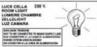 | Room light cable |
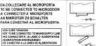 | Microdoor cable |
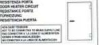 | Door heater cable |
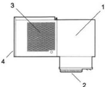
3. DESCRIPTION OF THE UNIT
The SB series includes air-cooled or water-cooled (optional) condensing units built on the basis of the single-block principle. They consist of:
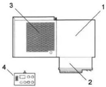
- a condensing unit placed outside the cold room;
- an evaporator placed in an insulated box and installed outside the cold room;
- an electric control panel placed on the condensing unit;
- a wall-mounted remote control panel.
4. OPERATION
SB single blocks are compression units where cold is produced by vaporizing a liquid refrigerant (HFC type) at low pressure in a heat exchanger (evaporator). The resulting vapour is brought again into the liquid state by mechanical compression at a higher pressure, followed by cooling in another heat exchanger (condenser). The compressor is hermetic, with reciprocating motion, supplied with single-phase or three-phase power. Defrost takes place automatically in pre-set cycles; manual defrost is also possible.
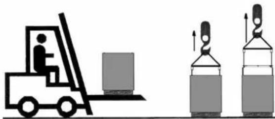
5. HANDLING
The unit can be handled by lifting and transport means.
natural_image
Illustration of a forklift and two stacked storage tanks with upward arrows indicating flow or operation (no text or symbols)
WARNING
Make sure that no one is in transit in the operating area of the lifting/transport means to prevent any possible accidents to people.

If the unit is in a wooden case or crate, sling the packing properly before handling it.
Lifting speed shall be such as not to make the packed unit oscillate dangerously and possibly fall.
6. INSTALLATION
6.1 Plates
The unit is supplied with warning and attention plates as listed in the relevant table.
6.2 Dimensions
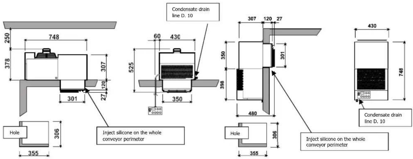
SB0 (SB120 O) SBV (SB120V)
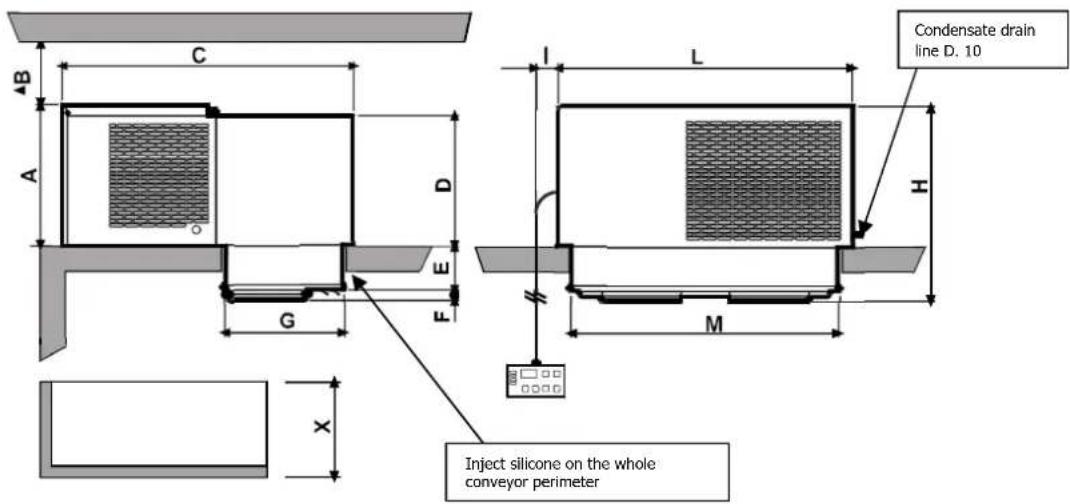
| Mod. | A | B | C | D | E | F | G | H | I | L | M | X | Y |
| SB1(125) | 357 | 250 | 719 | 340 | 122 | 28 | 332 | 506 | 60 | 620 | 545 | 337 | 550 |
| SB2(225) | 390 | 250 | 809 | 360 | 122 | 28 | 332 | 540 | 60 | 820 | 745 | 337 | 750 |
| SB3(135) | 427 | 250 | 929 | 410 | 122 | 98 | 452 | 645 | 60 | 820 | 745 | 456 | 750 |
| SB4(140) | 540 | 250 | 1042 | 410 | 122 | 98 | 452 | 760 | 60 | 920 | 745 | 458 | 750 |
| SB5(235) | 542 | 250 | 1046 | 520 | 122 | 98 | 452 | 785 | 60 | 1075 | 1000 | 458 | 1005 |
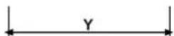
6.3 Location
To obtain optimal operation of the unit act as follows:
A) Place the unit in a well ventilated room, far from heat sources.
B) Limit the number of door openings.
C) Make sure that the unit has good air supply and discharge.
D) Fit a drain line to the defrost water drain connection in the lower part of the unit.
Note: SB units are equipped with automatic evaporation of defrost water;
drain is just a precaution in case of troubles.
flowchart
graph TD
    A["Inject silicone on the whole conveyor perimeter"] --> B["Solution 1"]
    A --> C["Solution 2"]
    B --> D["Flow direction arrows"]
    C --> E["Flow direction arrows"]
    D --> F["Final output"]
    E --> G["Final output"]
6.4 Free room
When installing the unit leave enough free room to allow opening, correct use and easy maintenance in safe conditions.
6.5 Installation
A) Prepare a opening with suitable dimensions in the cold room wall (see pictures above). Position the unit onto the cold room wall inserting the evaporator section in the opening.
B) Fix the unit using the screws supplied.
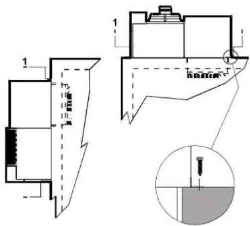
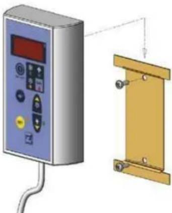
6.6 Fitting the remote panel:
Fix the back plate to the wall using the pre-drilled holes; be careful the panel is kept in a vertical position. Fit the connecting cable between panel and unit making sure not to bundle it with other cables.
natural_image
Illustration of a control panel connected to a yellow mechanical bracket (no text or symbols visible)

ATTENTION
Check that the unit and its devices have suffered no damages during transport. Pay special attention to the components secured to the electric panel door and to the refrigerating circuit pipes. Mount the unit as shown in the drawings; make sure that the electric connections are carried out properly.
6.7 Safety devices
The following mechanical safety devices are supplied:
- Fixed upper and side protections for evaporator and condensing unit, secured by locking screws.
- External fan protections placed on the evaporating and condensing units, secured with screws.
The following electrical safety devices are supplied:
a. Protection of fans (belonging to motors) against high power absorption; with automatic reset.
b. High pressure switch (only for special components) to protect against excessive pressure; with automatic reset.
WARNING
Above devices have been developed to safeguard the operator's safety.
6.8 Cleaning
Clean the unit carefully. Remove any dust, foreign substances and dirt possibly deposited during handling. Use detergents and degreasers.

ATTENTION
Solvents are not allowed.
7. CONNECTING THE UNIT

ATTENTION
Before connecting the unit make sure that mains voltage and frequency correspond to the values shown in the data plate. Voltage tolerance: +/- 10% compared to nominal value.
7.1 Electric connection
Connect the unit after checking the panel components.

ATTENTION
Connection to the electric line shall be effected applying a suitable safety device (a circuit breaker or a ground fault interrupter) selected by the installer on the basis of the line involved and of the absorption indicated on the unit plate.
If a cold room includes more units, each unit shall be provided with its own safety device.
Connect the unit paying attention to the colours of the supply cable wires:
a) 230V/1/50-60Hz
3 wires
Blue = Neutral
Yellow/Green = Ground
Brown = Phase
b) 230V/3/50-60Hz 4 wires Grey = Phase
Yellow/Green = Ground
Brown = Phase
Black = Phase
c) 400/3/50 Hz 5 wires Blue = Neutral
Yellow/Green = Ground
Brown = Phase
Black = Phase
Grey = Phase
We advise to install a microswitch (not supplied) on the cold room door which will
- switch on the light in the cold room, stop the unit and
- override the temperature alarm (for about one hour after
door closing) every time the door is opened.
The necessary cable is available with the unit. Connect it keeping in mind the following:
microswitch closed = door closed.
ATTENTION
Above microswitch is not supplied with the unit. If the microdoor cable is disconnected or damaged, the same conditions will occur as in case of open door and connected microdoor.
"B" RANGE units (B = low temperature) are supplied with a cable for door heater connection, to be made using a fuse suitable for the door heater used.
The unit is also equipped with a cable for cold room lamp connection (lamp voltage should be 230 V and lamp max capacity 100 Watts).

ATTENTION
Do not connect microdoor, cold room light or door heater cables to the 230V line. Each cable is equipped with a plate showing how it should be connected.
WARNING
Any defective electrical part should be replaced by trained personnel exclusively.
The electric connection should be effected by qualified personnel.
7.2 Connection to water system (water condenser)
This connection is only necessary if the unit has a water-cooled condenser. It is effected by following the indications of the tags positioned by the INLET and OUTLET pipes. Connection pipes should never be smaller in diameter than those on the unit. A minimum water pressure of 1 bar is required for correct operation of the unit.
8. ELECTRIC CONTROLS
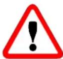
8.1 Control panel
|
 | Control LED (GREEN)ON: compressor is running, unit is refrigerating.Flashing: compressor is in start delay mode.OFF: compressor is off, room temperature is down to set value |
 | Control LED (GREEN)ON: evaporator fan is running.Flashing: evaporator fan is in start delay mode. OFF: evaporator fan is off. Defrost is in course. |
| [14T8] | Control LED (YELLOW)ON: Automatic or manual defrost is in course. |
 | Alarm LED (RED)ON: alarm has been activated because of a malfunctioning sensor, or pressure switch intervention, or cold room temperature exceeding allowed tolerances.OFF: Unit is operating normally. |
| [44H9] | DISPLAY: on connection to the mains it shows OFF to indicate the condition of the unit. By pressing ON/OFF key for 3 seconds the unit is turned ON and the display shows the cold room temperature. In programming mode the parameters to be set are displayed; in alarm mode the alarm code is displayed. |
| [722B] | "SET" key: when pressed it lights up and allows room temperature to be set. During programming it is used to pass from a submenu to an |
 | "DOWN/ROOM LIGHT" key: in programming mode or when setting room temperature it is used to reduce the value displayed; otherwise it is used to switch on/off the cold room light. |
 | "SB.M./UP" key: in programming mode it is used to increase the values displayed. If pressed for more than 5 seconds it enables manual defrost to be carried out. |
 ON/OFF ON/OFF | "ON/OFF" key: when pressed for 3 seconds it turns the unit on or off. |
| [9ZZ0] | "Enter" key: it gives access to programming menu and submenus. Access to the programming mode requires the installator's assistance and should be effected only if necessary. |
9. CHECKS, REGULATIONS AND ADJUSTMENTS
Before turning the unit on, check that:
- locking screws are tight
- electrical connections have been carried out correctly.
In the event that the unit has been opened:
- no tools were left inside
- assembly is correct
- there are no gas leaks
- front cover is secured correctly
9.1 Starting
Before starting the unit act as follows:
- Connect the unit to the mains. The display is turned on and shows OFF.
- If the unit has a preheating cycle, leave it in this condition for at least 3 hours.
- If the unit has a voltage monitor, leave it in this condition for at least 7 minutes to have the counting phase carried out.
- Press ON/OFF key to switch the unit on.
- Set the required cold room temperature.

ATTENTION
Medium temperature range: +10 -5°C
Low temperature range: -15 -25°C
Setting room temperature:
- Connect the unit to the mains. OFF is displayed.
- Press ON/OFF key, for 3 seconds, to switch the unit on.
- Press SET key. The wellow led lights up and the previously set temperature is displayed.
• To change this value press following keys:
UP to increase temperature
DOWN to decrease temperature
Press SET key to confirm the set value or wait 15 seconds, Now the unit is operating and does not require any further programming. The refrigerating cycle is fully automatic according to the factory-set parameters, which can be modified by authorised personnel only.

ATTENTION
24 hours after starting check evaporator state. If ice has formed, defrost frequency should be increased. In low temperature units the evaporator condition should be checked every week during the first month of operation.
9.2 How to Lock / Unlock the keyboard
Lock
- Keep pressed for more than 3" and keys.
- The (POF) message will be displayed and the keyboard will be locked. At this point it will be possible only to see the set point or the Max o Min temperature stored.
- If a key is pressed more than 3" the (POF) message will be displayed.
Unlock
- Keep pressed together for more 3" and keys, till the (Pon) message will be displayed.
10. WIRING
A wiring diagram, specific for the units of the SB series, is enclosed with these use and maintenance instructions.
11. MAINTENANCE AND REPAIRS
Suitable maintenance is crucial for obtaining longer life, perfect working conditions and high efficiency of the unit as well as for ensuring the safety features provided by the manufacturer.
12. ROUTINE MAINTENANCE
Good operation of the unit requires the condenser to be cleaned periodically (frequency of cleaning depends on the environment where the unit is installed).
Turn off the unit and clean it by blowing air from the inside outwards. Should no air jet be available, use a long-haired brush and work on the outside of the condenser.
In case of water-cooled condensers have the unit cleaned by a plumber with special descaling agents.

WARNING
Use safety gloves to protect your hands from possible cuts.

WARNING
Disconnect the unit before working on it.
12.1 Periodical maintenance
Periodically check wear condition of electrical contacts and remote switches; if necessary replace them.
12.2 Service operations to be carried out by qualified technicians or by the manufacturer
Following operations shall be carried out by qualified technicians or by the manufacturer exclusively. Under no circumstances the user is allowed to:
• replace electrical components
• work on the electric equipment
• repair mechanical parts
• work on the refrigerating system
• work on the control panel, ON/OFF and emergency switches
• work on protection and safety devices.
12.3 Troubleshooting
During operation following troubles may occur:
- Compressor stops. The unit is equipped with an overtemperature device which stops the compressor every time the max. allowable temperature of motor windings is exceeded.
Possible causes are:
- insufficient ventilation of the room where the unit is installed;
- anomaly in mains voltage;
- faulty operation of condenser fan.
Device reset is automatic.
- Ice forms on the evaporator preventing air from flowing regularly.
Possible causes are:
- the door is opened too frequently;
- faulty operation of evaporator fan;
- faulty solenoid valve (in models with hot gas defrost);
- faulty defrost heater (in models with electric defrost);
- faulty defrost process.
In this case some measures can be taken:
increase defrost termination temperature by some degrees, increase number of defrosts.

ATTENTION
Do not use either hot water or any pointed, cutting, metal objects to remove ice blocks.
-
Display does not light up. Check:
-
if there is power to the unit;
- if mains cable is connected properly;
-
fuses inside the electric panel
-
Unit does not start operating when pressing ON/OFF key (the display is turned on): check microdoor connection keeping in mind that the switch contact must be closed when the door is closed.
Unsatisfactory efficiency of the unit:
If no defects are found in the unit check that: cold room doors are perfectly tight; there is no cold dispersion; the cold room is used wisely; no unfrozen liquids or foodstuffs are placed in the low temperature room; the evaporator is ice-free. We recommend installation of the machines far from the doors especially when the cold room is expected to be opened many times a day.
WARNING:
Removal of protections during machine operation is absolutely forbidden. They have been developed to safeguard the operator's safety.
12.4 Alarms
When the unit is in alarm mode, the control LED lights up, the buzzer (available if installed by the customer) starts operating and the display shows an alarm code allowing the immediate identification of the alarm.
| ALARM | DISPLAY | CAUSE | REMEDY |
| High temperature | (HA) alternating with cold room temperature. | Excessive door openings. Too high temperature of products stored. Malfunction of the unit. | |
| Low temperature | (LA) alternating with cold room temperature. | Malfunction of electronic controller | Service intervention |
| Room sensor | Steady (P1). | Sensor not connected | Replace sensor |
| Evaporator sensor | (P2) alternating with cold room temperature | Sensor not connected | Replace sensor |
| Open Door | (dA) alternating with cold room temperature | Door opening time exceeds max opening by parameter | Automatic reset when the door is closed. |
| High/Low pressure | (PrE) alternating with room temperature; LED (4) lights up each time the high or low pressure switch is tripped. If more than 10 trips occur in one hour, then (PAL) alternating with cold room temperature is displayed and alarm relay is activated together with LED (4). In this situation all functions are interrupted. | Faulty operation of condenser fan. Check condenser cleaning and gas charge. | Switch off the refrigerating unit, wait a few seconds and switch on again. |
| Voltage monitor | (bAL) alternating with cold room temperature. The voltage monitor is an electronic device which checks the supply voltage of the unit when voltage variations exceed +/-12%. The unit stops for about 6 minutes and restarts automatically if voltage is within the prescribed limits. Warning: on first starting the monitor carries out a counting phase of 7 minutes, during which the unit should be left connected but in OFF condition. | Wrong supply voltage | |
13. HOW TO ORDER SPARE PARTS
When ordering spare parts make reference to the number written on the unit plate.
WARNING
Worn parts should be replaced only by qualified personnel or by the manufacturer.
14. HOW TO DISPOSE OF THE PACKING
Wooden, plastic, polystyrene packing shall be disposed of according to the regulations in force in the country where the unit is used.
15. HOW TO DISPOSE OF THE UNIT
Do not discharge scrapped components in the environment. They should be disposed of by companies dealing with special waste collection and recovery, according to the regulations in force in the country where the unit is used.
WARNING
Do not discharge the refrigerant in the atmosphere. It should be disposed of by companies dealing with special waste collection and recovery.
natural_image
Simple line drawing of a table with a cart and wheels, crossed by diagonal lines (no text or symbols)
Declaration of conformity with article 14 of the EU regulation no.517/2014 of the European Parliament and Council
The undersigned company ZANOTTI SPA – VAT NUMBER 01856570203 declares under its own responsibility that the pre-loaded machineries it manufactures contain hydrofluorocarbons contained in the quota system of the Union indicated in Chapter IV of the EU regulation no. 517/2014 as:
☐A. it is holder of authorizations issued in compliance with article 18, paragraph 2, of the EU regulation no. 517/2014 and registered in the register indicated in article 7 of such regulation, at the moment of release for free circulation for the use of the quota of a manufacturer or importer of hydrofluorocarbons, without prejudice to article 15 of the EU regulation no. 517/2014, for the quantity of hydrofluorocarbons contained in the equipment.
☐B. the hydrofluorocarbons contained in the machineries have been placed on the market of the Union, subsequently exported and loaded in the machineries outside the Union, and that the company which has placed the hydrofluorocarbons on the market has issued a declaration in which it states that the quantity of hydrofluorocarbons has been or will be marked as placed on the market of the Union and that it has not been and will not be marked as supply designed for export pursuant article 15, paragraph 2, letter c), of the EU regulation no. 517/2014 and of the point 5C of the annex of the EU Implementing Regulation no. 517/2014 of the Commission.

the hydrofluorocarbons loaded in the machineries have been placed on the market by a manufacturer or importer of hydrofluorocarbons to which article 15 of the EU regulation no. 517/2014 applies.
Pegognaga, 01/01/2017
Chief Executive Officer
Wakio-Mawchi
INDEX
natural_image
Illustration of a forklift and two stacked industrial lifting devices (no text or symbols)
AVERTISSEMENTS
flowchart
graph TD
    A["Solution 1"] --> B["Flow Direction"]
    C["Solution 2"] --> D["Flow Direction"]
    E["Solution 3"] --> F["Flow Direction"]
    G["Solution 4"] --> H["Flow Direction"]
    I["Solution 5"] --> J["Flow Direction"]
    K["Solution 6"] --> L["Flow Direction"]
    M["Solution 7"] --> N["Flow Direction"]
    O["Solution 8"] --> P["Flow Direction"]
    Q["Solution 9"] --> R["Flow Direction"]
    S["Solution 10"] --> T["Flow Direction"]
    U["Solution 11"] --> V["Flow Direction"]
    W["Solution 12"] --> X["Flow Direction"]
    Y["Solution 13"] --> Z["Flow Direction"]
    AA["Solution 14"] --> AB["Flow Direction"]
    AC["Solution 15"] --> AD["Flow Direction"]
    AE["Solution 16"] --> AF["Flow Direction"]
    AG["Solution 17"] --> AH["Flow Direction"]
    AI["Solution 18"] --> AJ["Flow Direction"]
    AK["Solution 19"] --> AL["Flow Direction"]
    AM["Solution 20"] --> AN["Flow Direction"]
    AO["SB0 SBV"] --> AP["A"]
    AQ["SB120"] --> AR["A"]
    AS["SB1"] --> AT["A"]
    AU["SB125"] --> AV["A"]
    AW["SB2"] --> AX["A"]
    AY["SB225"] --> AZ["A"]
    BA["SB3"] --> BB["A"]
    BC["SB135"] --> BD["A"]
    BE["SB4"] --> BF["A"]
    BG["SB140"] --> BH["A"]
    BI["SB5"] --> BJ["A"]
    BK["SB235"] --> BL["A"]
natural_image
Illustration of a control panel connected to a yellow mechanical bracket (no text or symbols visible)
ATTENTION
AVERTISSEMENTS
natural_image
Two identical black-and-white icons: one with a snowflake and flower, the other with a sun and downward arrow (no text or symbols)
UP pour augmenter
DOWN pour diminuer
natural_image
Symbol of a trash bin with no text or labels
natural_image
Illustration of a forklift and two stacked industrial lifting devices (no text or symbols)
HINWEISE
natural_image
Illustration of a control panel connected to a yellow mechanical bracket (no text or symbols visible)
ACHTUNG
HINWEISE
natural_image
Two identical black-and-white icons: one with a leaf and flower, the other with a lightbulb and downward arrow (no text or symbols)
natural_image
Symbol of a trash bin crossed out by two diagonal lines, representing no waste or discharge (no text or labels)
natural_image
Illustration of a forklift and two stacked industrial lifting devices (no text or symbols)
AVISOS
natural_image
Illustration of a control panel connected to a yellow metal bracket (no text or symbols visible)
CUIDADO
AVISO
natural_image
Pure electrical circuit lines without any symbols
ACUSTIC TEMPERATURE ALARM
SONNERIE ALARME TEMPERATURE
TEMP.- ALARMWECKER
ALARMA SONORA DE TEMPERATURA
SINALEIRA ALARME DE TEMPERATURA
K1
TELERUTTORE COMPRESSORE M1
COMPRESSOR M 1 CONTACTOR
The equipment contains fluorinated greenhouse gases.
natural_image
Abstract black-and-white geometric pattern with horizontal lines and diagonal stripes (no text or symbols)
ZANOTTI
a member of DAIKIN group
Zanotti S.p.A.
Via M.L. King, 30 - 46020 Pegognaga (MN) Italy
Tel. 0376.5551 - Fax 0376.536554
info@zanotti.com - www.zanotti.com
0MAN052/S
01/2018