Phantom CI AMP-2500 DSP - Audio Amplifier Dali - Free user manual and instructions
Find the device manual for free Phantom CI AMP-2500 DSP Dali in PDF.
| Product type | In-wall audio amplifier (Custom Installation) |
| Brand | DALI |
| Model | Phantom CI AMP-2500 DSP |
| Dimensions (H x W x D) | 88 x 440 x 320 mm (2U rack) |
| Net weight | 5.6 kg |
| Power supply | 100-240 V AC, 50/60 Hz, universal with power factor correction |
| Standby power consumption | < 0.5 W |
| Output power (stereo, 4 Ω) | 2 x 500 W |
| Output power (mono BTL, 8 Ω) | 1 x 1000 W |
| Number of channels | 2 (configurable as stereo, mono, Hi-Z or BTL) |
| Analog inputs | 4 balanced (Euroblock) + 4 unbalanced (RCA) |
| Digital input | 1 stereo S/PDIF (RCA) |
| Speaker outputs | 2 channels on Euroblock connectors (up to 2.5 mm²) |
| Network connectivity | Ethernet (RJ45) and WiFi (access point or client) |
| Configuration interface | Web interface via browser (DALI PHANTOM CI AMP CONFIGURATOR) |
| DSP functions | Loudspeaker profiles, parametric EQ, crossover, delay, limiter, FIR, input/output routing |
| External control | GPIO (volume, standby, mute, 12V trigger) |
| Protections | Short circuit, overvoltage, overheating, clipping |
| Operating temperature | 0 °C to 40 °C |
| Included accessories | Mains cable, Euroblock connectors (inputs, outputs, GPIO), 4 adhesive feet |
| Cleaning | Use a soft, dry cloth. Do not use liquids or aerosols. |
| Repairability | Contact a qualified technician. No user-serviceable parts. |
| Warranty (approx.) | 2 years (according to local legislation) |
Frequently Asked Questions - Phantom CI AMP-2500 DSP Dali
User questions about Phantom CI AMP-2500 DSP Dali
0 question about this device. Answer the ones you know or ask your own.
Ask a new question about this device
Download the instructions for your Audio Amplifier in PDF format for free! Find your manual Phantom CI AMP-2500 DSP - Dali and take your electronic device back in hand. On this page are published all the documents necessary for the use of your device. Phantom CI AMP-2500 DSP by Dali.
USER MANUAL Phantom CI AMP-2500 DSP Dali
DALI PHANTOM CI AMP-2500 DSP
INSTALLATION GUIDE
USER MANUAL

DALI PHANTOM CI AMP-2500 DSP
INSTALLATION GUIDE / USER MANUAL
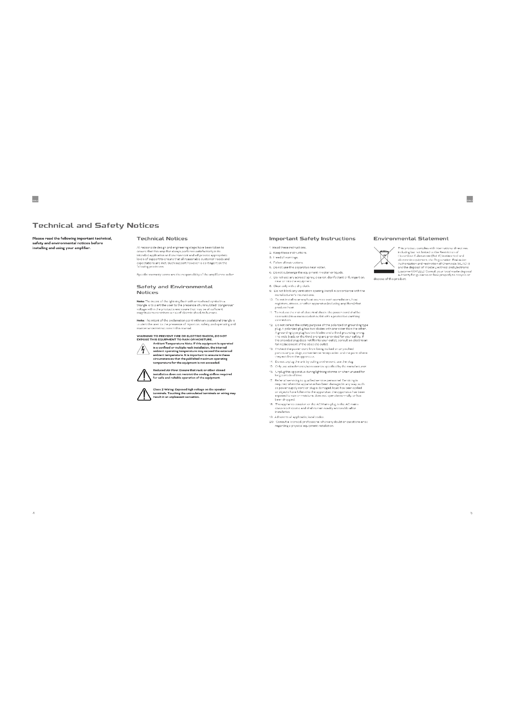
Technical and Safety Notices
Please read the following important technical, safety and environmental notices before installing and using your amplifier.
Technical Notices
All reasonable design and engineering steps have been taken to ensure that the smaller always part of the material is normally in its intended application and environment, and will provide appropriate levels of support to ensure that all reasonable conditions or conditions expectations are met. Such supports however can contingent on the following provisions.
Specifically similar results are the randomly low values of the amplifier re-meter
Safety and Environmental Notices
Note: The extent of the lighting flash with an inverted symbol in a triangle is to alert the user to the presence of uninsulated "congenous" value within the product is enough that may be of sufficient ingredients to constitute a risk of clean stock to humans.
Note: The intent of the explanation point within an equilateral triangle is to start the author to the presence of important society, and operative and maintenance instructions in this material.
WARNING TO PREVENT FIRE OR ELECTRIC SHOCK, DO NOT EXPOSE THIS EQUIPMENT TO RAIN OR MOISTURE.

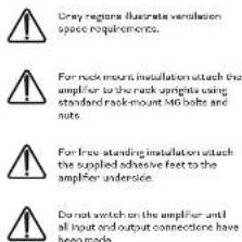
Ambient Temperature Note: If this equipment is operated in a confined or multiple rock installation, the internal ambient operating temperature may exceed the external ambient temperature. It is important to ensure in these circumstances that the published maximum operating temperature for the equipment is not exceeded.

Reduced Air Flow: Ensure that rack or other closed installation does not restrict the cooling airflow required for safe and reliable operation of the equipment.

Class 2 Wiring: Exposed high voltage on the speaker terminals. Touching the uninsulated terminals or wiring may result in an unpleasant sensation.
Important Safety Instructions
-
Read these instructions.
-
Keep these instructions.
-
Headline earnings.
-
Follow all instructions.
-
Do not use this apparatus near water
-
So not subcontinue the equipment in water or liquids.
-
Деталан жеремателей нау, сложен, доспектелей огларынел ир.
nech or into the equipment.
B. Clean only with a dry cloth
- In red black any ventilation opening install in accordance with the
The following table is in English.
10 Do not install near dry nest sources such as rotators, hect registers, staves, or other apparatus (including aquifers), that structure heat
-
To reduce the risk of electrical shock, the power contained is connected to a main socket outlet, with a protective carding connection.
-
On the basis the safety purpose of the pulsed or grouting type plug. A pulsed plug uses a hollow with one outer than the other. A grouting type plug has two blades and a hard pressing angle. The wide blade or the third being pre-provided for your safety if the provided plug does not fit into your outlet, consult on electric oven for replacement of the obsolete outlet.
-
Protect the lower cord from being walked on or pinched particularly at slugs, convenience receptacles, and the point where they exit from the apparatus.
M. Do not plug the unit by pulling on the cord use the plug
-
Only use attachments/accessories specified by the manufacturer
-
Unplug the apparatus during lighting storms or when unused for long periods of time.
-
Staller of being up to qualified outside perinatal gathering in required when the apparatus has been damaged in any way, such as power supply cord or plug is damaged, liquid has been polled or objects have fallen into the apparatus, the apparatus has been exposed to rain or moisture, does not operate normally, or has been dropped.
-
The spolence coupling or the AC Mars plug is the AC mains disconnect device and shall remain readily accessible after installation.
12 Adhere to all applicable local cases.
- Consult a license professional when any doubt or questions arise regarding a physical equipment installation
Environmental Statement

The product complex with internation directives, including but not related to the destruction of Hydroelectric Appliances (Kan. 85) in electrical and electronic instruments, the preparation, maintenance, authorization and restriction of Chemicals (REACH), and the disposal of Woste Electric-Iceland Electronic Equipment (WLT I). Conduct your local waste disposal author by a guide on how properly to recycle an
dispose of this product
Contents
- Introduction 6
2 Overview 7
-
Pack Contents 8
-
Installation 9
-
Initial Configuration 10
-
Connections 14
-
Operation 20
-
Advanced Configuration 22
1. Introduction
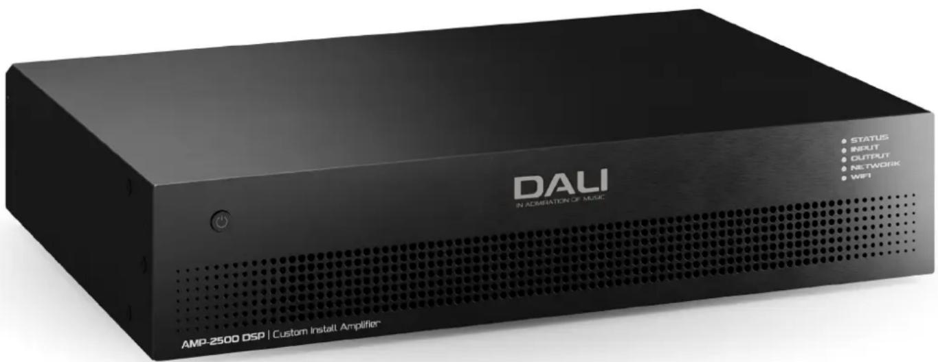
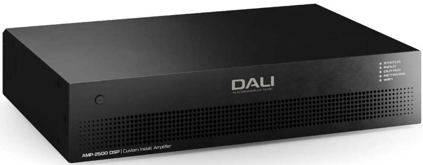
The DALI PHANTOM CLAMP-2500 DBP amplifier is designed to provide high performance and configurable audio power amplification for all DALI PHANTOM custom install speakers and subworkers. It can however also be used to power conventional DALI passive hi-fi speakers.
This manual covers the features, installation and functions of the AMP 2500 DGP. Please read the manual fully before installing and using the amplifier. If you have any questions regarding amplifier configuration, installation or operation please contact your DALI retailer or installer, or DALI directly via the support pages at dali-speakers.com.
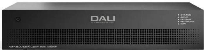
2. Overview
The AMF-2500 DSP is a full rack width, 2U format two channel power amplifier rated at 600 Watts per channel. It is able to power up to four DALI CHUBH 8-100 subwoofer simultaneously on one or two front or surround channel speakers. The AMF-2500 DSP provides four analogue inputs and one stereo S/PDIF digital input.
The AMP-2500 DSP is comprehensively equipped with DSP (digital signal processing) functions that enable it to be configured via the DAL-PHANTOMOAMP CONFIGURATOR with specific functional profiles designed for individual DAL speaker models.
The AMP 2500 DBP is by default act up with the DALI PHANTOM IV SUB S-100 functional profile installed. Installing profiles for alternative speakers is covered in Section b of this manual. DALI AMP-2500 DBP functional profiles for other speakers can be downloaded from: dali-speakers.com
2.1 DALI PHANTOM CI AMP CONFIGURATOR
The DALI PHANTOM CI AMP\~2500 DSP provides comprehensive DSP based configuration menus accessible via the DALI PHANTOM CI AMP CONFIGURATOR web interface.
Access to the AMP CONFIGURATOR interface is made through wind (Ethernet) or wireless (WiFi) network connection to the AMP 2500 DSP other directly from a configuration device such as a smart phone or computer, or via a network router or switch.
The AMP CONFIGURATOR cover Speaker Profiles, Inputs, Outputs and General Settings and is described in Sections 5 and 8 of this manual. Connecting the AMP-2500 DSP to a wire or wireless configuration device on network is described in Section 5.2.

2.2 Amplifier Connections and Power Switching
AMT-250C DSP signal input and output connections are accomplished via ROA Phono and Euroblock style connectors. A GPIO (General Purpose In/Out) Eurolock connector enables some amplifier functions to be controlled externally, and wireless or RJ-15 socket. Ethernet network connection options are also provided. Cable connectors and connections are described and illustrated in Section 6 of this manual. Connection and use of the GPIO socket is described in Section 5.
AMP-2500 DSP amplifier incorporates a front panel mounted power button. Press the button once to switch the amplifier on or off. Amplifier power management behaviour can be configured via the Control web interface [Settings] Menu described in Section 5 of this manual.
2.3 Firmware
This manual describes the features, functions and user interface of the AMP-2500 DSP amplifier running Firmware Version 1.3.3.
It is strongly recommended that the firmware version installed in the amplifier in use is checked initially, and regularly thereafter. If updated firmware is available, the amplifier should be updated as a priority.
The firmware installed in the amplifier can be identified and updated by selecting the [Device] option in the AMP CONFIGURATOR web interface [Settings] Manual Firmware versions can be checked, and firmware downloaded, from the website: osi-sspeakers.com
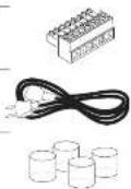
3. Pack Contents
The AMP-2500 DSP amplifier is shipped in a cardboard carton containing the amplifier unit, accessories, a main cable appropriate for the sales territory, and a document pack. The full contents is illustrated below.
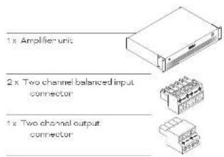
1x GPIO socket connector
1 x Mains power cable
4 x Adhesive rubber feet
4. Installation
4.1 Amplifier Location
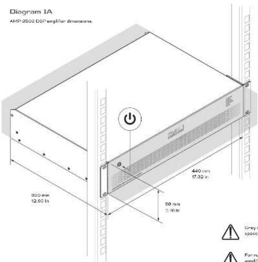
The AMP-2500 DSP amplifier is shipped with rack "ears" attached and are primarily intended for standard (19 inch) equipment rack installation.
If not to be installed in an equipment rack, the AMP 2500 DSP amplifier can be placed free-standing on a flat surface. Adhesive rubber feet are supplied for the purpose. The rack ears can be removed if desired by unscrewing the six securing screws (three each side).
It is important that any installation provides space for airflow through the ventilation apertures at the front and rear of the amplifier. This is illustrated in Diagram 1A.
5. Initial Configuration

Before making input, output or GPIO connections to an AMP-2500 DBF amplifier; it is important that it is configured appropriately, or has the appropriate functions' profile installed, speakers that are to be used.
The AMP-2500 DSP is by default configured with a DALI PHANTOM IW SUB 5-100 subwoofer functional profile installed. Deleting or modifying the IW SUB 5-100 profile, or installing a profile for an alternative DALI speaker, requires that the AMP-2500 DSP amplifier is connected to mains power, switched on, and connected to either a TCP/IP network or directly to a configuration device for access to the DALI CI AMP CONFIGURATOR web interface.
NOTE
If access to the AMP CONFIGURATOR is not required jump to Section 6 of this manual for guidance on audio signal and IW SUBS-100 subwoofer connections. Establishing network access to the AMP CONFIGURATOR is however recommended in all cases.
5.1 Mains Power Connection
The AMP 2500 DSP amplifier incorporates a power factor corrected universal power supply and can be used with mains input voltage from 10CV AC to 24CV AC, b0/60Hz. Use the mains cable supplied with the amplifier and connect it to a mains supply.
Press the front panel power button to switch on the amplifier. After a short delay the front panel Status indicator will illuminate green.
5.2 Amplifier Network Connection
The AMP 2500 DSP amplifier is configured via the DAL PHANTOM OF AMP CONFIGURATOR web interface. Before the configuration menus can be accessed, the AMP-2500 DSP amplifier must be either connected to the same network as the configuration device, or connected directly to a configuration device via either WiFi or Ethernet. The configuration device can be a smart phone, tablet or computer.
5.2.1 Wired (Ethernet) Connection
To connect an AMP 2500 DSP amplifier to a TCP/IP network or directly to a configuration device using a wired connection (Ethernet) follow the steps below.
- Use an Ethernet cable to connect the AMP 2500 DGP amplifier near panel [Network Control] socket to a free socket on a network router or switch, directly to an Ethernet equipped laptop or desktop computer.
- With the AMP-2500 DSP amplifier connected to main power and switched on the front panel [Network] indicator will illuminate gain to indicate that the amplifier has network connectivity.
- The AMP 2500 DIP amplifier default: AN IP address is 192.168.64.100. Configure the laptop or desktop computer for a fixed IP address in the same IP range; eg 182.168.64.10, with Subnet mask of 255.255.255.0 (or prefix 24) and set the Gateway to 192.168.64.1
- Open a smart phone, tablet or computer web browser and enter the IP address. http://192-168.84100. The DALIP-PHANTOM OIAMP CONFIGURATOR web interface will open to enable amplifier configuration as required.
NOTE:
AMP-2500 DSP amplifiers can be configured to use DHCP for network connection if required. However, if a AMP-2500 DSP amplifier using DHCP is switched off and on, it is possible that the TCP/IP network router will assign a different IP address, leaving its configuration page inaccessible via the previous IP address. If this occurs a network scanning app can be used to identify the new IP address, DHCP and Fixed IP address option settings can be found in the AMP CONFIGURATOR [Settings] menu described in Section 8 of this manual
5.2.2 Wireless (WiFi) Connection
To connect an AMP 2500 DSP amplifier to a TCP/IP network or directly to a configuration device using a wireless connection (WIFI) follow the steps below.
1. With the AMP 2500 DSP amplifier connected to main power and switched on, the front panel WiFi indicator will illuminate green to indicate the WiFi is available.
2. Use a mobile, isop or desktop device to search for available WiFi networks. Connect to "AMP-2500 DSP" (product serial number)* using the password (*password*) The ampifice serial number can be found on its rear panel.
3. Open a smart phone, tablet or computer web browser and enter the IP address. 192.169.4.1. The DALI PHANTOM OAMP CONFIGURATOR web interface will open to enable amplifier configuration as required.
4. If it is required to connect the amplifier to an alternative WiFi network, select the AMP CONFIGURATOR [Settings] Tab followed by [WiFi > WIFI Mode > Client] to configure the amplifier to connect to the required WiFi network. The WiFi network name and password will be required.
It is strongly recommended that the AMP-2500 DSP amplifier Access Point WiFi password is changed following initial wireless connection.
5.3 The DALI PHANTOM CI AMP CONFIGURATOR
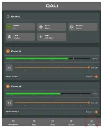
Opening the IP address 192.168.64.10 in a web browser that is network-connected to an AMP-2500 DGP amplifier displays the DALIPHANTOM CI AMP CONFIGURATOR web interface [Dashboard], illustrated in Diagram 5A. The Dashboard is the AMP CONFIGURATOR 'home' page from which all other configuration options can be processed.
The [Dashboard] displays the amplifier status, output zones and the configuration menu tabs. It also enables access to the functions that enable DALI speaker or subwoofer profiles to be managed. This is described in the following paragraphs:
NOTE:
Advanced amplifier configuration using the AMP CONFIGURATOR is described in Section 8 of this manual.
5.3.1 Standard functional profile, Backup and Restore
When an AMP-2500 DSP is used with DALL custom install in-wall speakers and subwoofera it is important that the correct functional profile is installed. Installing functional profiles is described in the following paragraphs.
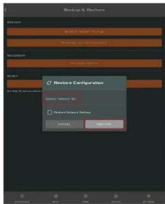
- Using a web browser app, open the DALI PHANTOM OAMP CONFIGURATOR and select [Settings] from the [Dashboard] followed by the [Backup & Restore] option.
- Selecting the [Backup & Restore] option will open the [Backup & Restore] menu and provide the option to restore the amplifier settings from a configuration file. This file will incorporate the appropriate functional profile data.
NOTE:
If the default profile IW SUB 5-100 subwoofer is to be deleted, select the [RESET] option. This will return the amplifier to its baseline state with no functional profile installed.
Diagram 5A
AMP CONFIGURATOR [Dashboard] display.
12 13
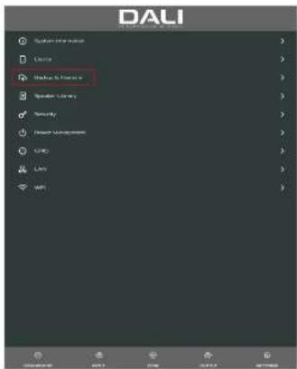
Diagram 5B
AMP CONFIGURATOR [Settings] menu
- Selecting [Restore Setup from file] will open a dialogue box that enables selection of a previously downloaded configuration file. Select [Select restore file], browse to the appropriate file and select the [Restore] option. The configuration file will be uploaded and automatically react the amplifier to the correct configuration for the speakers or subworkers to be used.
NOTE
If the appropriate configuration file has not been downloaded it can be found at: dali-speakers.com
With the appropriate functional profile installed it is recommended that the amplification is switched off while input, output and GPIO connections are made
NOTE
Do not tick the [Restina Network Settings] check box.
Diagram SC
AMP CONFIGURATOR [Backup & Restore] menu.
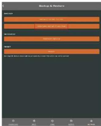
Diagram 5D
AMP CONFIGURATOR [Backup & Restore] menu.
6. Connections
DALI PHANTOM OI AMP-2500 DSP amplifier rear panel connections are illustrated in Diagram 6A.
6.1 Mains Power Connection and On/Off Switch
The AMP-2500 DSP amplifier incorporates a power factor connected universal power supply and can be used with mains input voltage from 100V AC to 240V AC, 50/60Hz. Use the mains cable supplied with the amplifier. Press the power button on the front panel once to switch the amplifier on or off.
6.2 Amplifier Input Connection
The AMP-2500 DGP amplifier provides four balanced or unbalanced analogue audio inputs and a atance S/PDIF digital audio input. Any input channel can be routed to any output channel. Input routing options can be configured via the DALIPHANTOM OFAMP CONFIGURATOR web interface. See Section 8 of this manual.
Analogue Inputs
AMP-2500 DBP analogue inputs are of the level format with a default input sensitivity of +4dBu (full output voltage swing/acoustivity) in all output modes. Depending on the selected sensitivity, the inputs can handle up to -24dBu without clipping. Input sensitivity options can be set via the AMP CONFIGURATOR web interface [Input] Tab. Sea Section 8 of this manual.
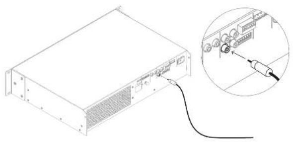
Balanced input connections to the amplifier are made via male "Euro Black" connectors. Connecting cables to the supplied female Input connectors is illustrated in Diagram 6D.
Unbalanced input connections to the amplifier are made via RCA phone sockets connected in parallel with the balanced inputs.
Digital Inputs
AMP-2500 DSP S/PDIF stereo digital audio input connections are made via the 'DIGITAL IN' ROA Phono socket. The S/PDIF input is connected by default to amplifier installation Zones 1 (left) and 2 (right).
Digital Outputs
AMP 2500 DSP S/PDIF stereo digital audio output connections are made via the 'DIGITAL CUT' RCA Phono socket. The S/PDIF output signal by default reflects the input to amplifier installation Zones 1 and 2 and is intended to be used for daisy-chaining AMP-2500 DSP amplifiers.
NOTE:
750 RCA phono cables specifically intended for digital audio should always be used for S/PDIF connections. Standard Phono cables can be used but may not result in optimal performance.
NOTE:
The 8/PDIF output level is by default set at -10dB to reduce the possibility of downstream input clipping.
Diagram 6A
AMP-2500 DSP rear panel connections.
![Network Control Configurable GPIO 5/30FIF Audio I/O Audio Inputs Balanced: Euroblock Unbalanced: RCM Phone Speaker Outputs Maine Power Input NETWORK CONTROL GPIO DIGITAL OUT N ANALOG INPUTS CH2 CH4 [WEI Antenna] [Do not touch] OUTPUTS COMPLIMINUM ACMANS JX 3800K 12-63HU/70W](/content/2026/04/640155/images/c04d62042a0a7c1d3139137a4ef7f4438f1b0239e96571fac076e0b069e884cb.jpg)
14 15
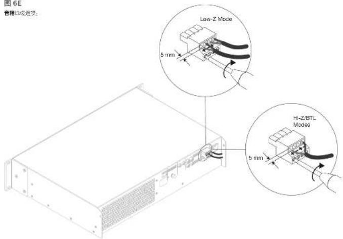
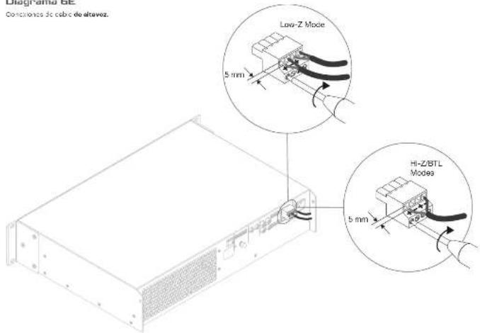
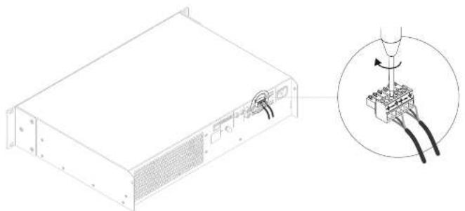
6.3 Speaker Connections
Speaker connections from the AMP-2500 DSP amplifier are made via male "Euro Block" connectors. Ensure that speaker connection polarity is correct throughout the installation:
In the case of conventional Lo-Z speaker connections, positive (+) amplifier terminals should always be connected to positive speaker terminals and negative (-) amplifier terminals always connected to negative speaker terminals.

In the case of HI-Z or BTL speaker connections, the two speaker cable conductors should be connected between the positive (+) terminal of Output 1 and the negative terminal (-) of Output 2.
NOTE:
Hi-Z and BTL speaker connection is not typically relevant to home audio systems and requires specialist knowledge. It should only be carried out by appropriately qualified audio technicians.
Output mode options (La Z or Hi-Z) can be configured via the AMP CONFIGURATOR [Output] Tab. See Section 8 of this manual.
Connecting cables to the supplied female output connector is illustrated in Diagram 6E.
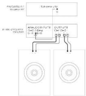
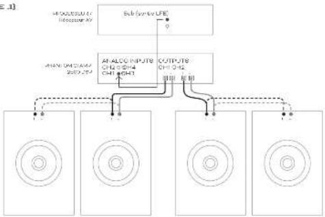
6.4 Subwoofer Connection Options
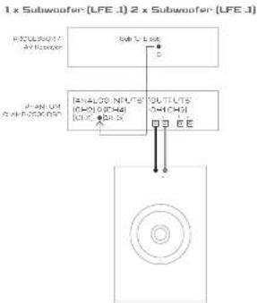
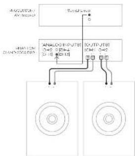
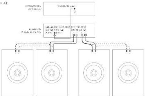
The AMP-2500 DSP is able to power a variety of DALI PHANTOM custom install speakers, however it is by default setup with the DALI PHANTOM IW SUB 5-100 subwoofer profile installed.
Up to four IW SUB S-100 subwoofers can be powered by one AMP-2000 DSP amplifier. The connection schemes recommended for systems comprising one, two and four subwoofers are illustrated in the Diagram 6B.
NOTE
The default amplifier input and output routing is shown in Diagram 6B. Alternative input and output routing can be configured via the AMP CONFIGURATOR. See Section 8 of this manual for information on input and output routing.
Diagram 6B
AMP-2500 DSP and IW SUB 8-100 connection schemes.
flowchart
graph TD
    A["Input"] --> B["Subwoofer 1"]
    B --> C["Output"]
    C --> D["Subwoofer 2"]
    D --> E["Output"]
    E --> F["Subwoofer 3"]
    F --> G["Output"]
    G --> H["Subwoofer 4"]
    H --> I["Output"]
    I --> J["Subwoofer 5"]
    J --> K["Output"]
    K --> L["Subwoofer 6"]
    L --> M["Output"]
    M --> N["Subwoofer 7"]
    N --> O["Output"]
    O --> P["Subwoofer 8"]
    P --> Q["Output"]
    Q --> R["Subwoofer 9"]
    R --> S["Output"]
    S --> T["Subwoofer 10"]
    T --> U["Output"]
flowchart
graph TD
    A["ANALOG-INPUT 0-2 3-1"] --> B["Ground"]
    C["ANALOG-INPUT 0-2 3-1"] --> D["Ground"]
    E["TO-UT-INPUT 0-1 3-1"] --> F["Ground"]
    G["Ground"] --> H["Ground"]
4 x Subwoofer (LFE .1)
flowchart
graph TD
    A["INPUT/OUTPUT"] --> B["AN-ALOG INPUTER"]
    A --> C[CH1-CH2-CH3-CH4-CH5-CH6-CH7-CH8-CH9-CH10-CH11-CH12-CH13-CH14-CH15-CH16-CH17-CH18-CH19-CH20-CH21-CH22-CH23-CH24-CH25-CH26-CH27-CH28-CH29-CH30-CH31-CH32-CH33-CH34-CH35-CH36-CH37-CH38-CH39-CH40-CH41-CH42-CH43-CH44-CH45-CH46-CH47-CH48-CH49-CH50-CH51-CH52-CH53-CH54-CH55-CH56-CH57-CH58-CH59-CH60-CH61-CH62-CH63-CH64-CH65-CH66-CH67-CH68-CH69-CH70-CH71-CH72-CH73-CH74-CH75-CH76-CH77-CH78-CH79-CH80-CH81-CH82-CH83-CH84-CH85-CH86-CH87-CH88-CH89-CH90-CH91-CH92-CH93-CH94-CH95-CH96-CH97-CH98-CH99-CH100
    style A fill:#f9f,stroke:#333
    style B fill:#ccf,stroke:#333
    style C fill:#ccf,stroke:#333
    style D fill:#cfc,stroke:#333
    style E fill:#fcc,stroke:#333
    style F fill:#fcc,stroke:#333
    style G fill:#fcc,stroke:#333
    style H fill:#fcc,stroke:#333
    style I fill:#fcc,stroke:#333
    style J fill:#fcc,stroke:#333
    style K fill:#fcc,stroke:#333
    style L fill:#fcc,stroke:#333
    style M fill:#fcc,stroke:#333
    style N fill:#fcc,stroke:#333
    style O fill:#fcc,stroke:#333
    style P fill:#fcc,stroke:#333
    style Q fill:#fcc,stroke:#333
    style R fill:#fcc,stroke:#333
    style S fill:#fcc,stroke:#333
    style T fill:#fcc,stroke:#333
    style U fill:#fcc,stroke:#333
    style V fill:#fcc,stroke:#333
    style W fill:#fcc,stroke:#333
    style X fill:#fcc,stroke:#333
    style Y fill:#fcc,stroke:#333
    style Z fill:#fcc,stroke:#333
16
6.5 Speaker Cable Gauge
AMP-2500 DSP speaker connection cable gauge should be chosen appropriately to reflect the type of installation. The adjacent tables specify the appropriate cable gauge and maximum cable length for less than 0.5d3 cable loss in Lo-Z mode and less than 1.0dB cable loss in Hi-Z mode.
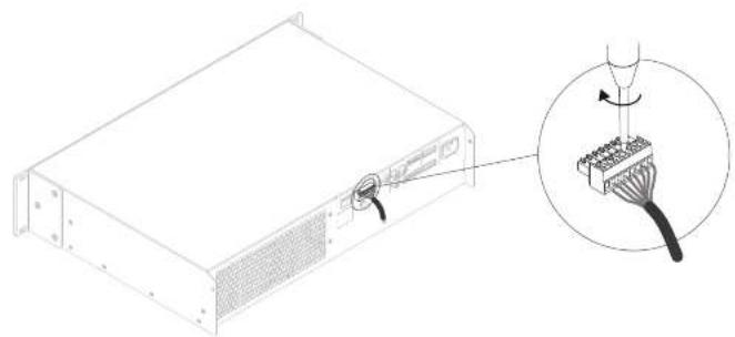
6.6 GPIO Connections
If any AMP 2500 DSP GPIO functionality is required, cables will need to be connected to the supplied GPIO connector. Connecting cables to the GPIO connector is illustrated in Diagram 6F.
6.7 Network Connections
The AMP-2500 DSP amplifier is a TCP/IP network connected device that is configured via a web page based interface. Wind (Ethernet) and wireless (WiFi) connection options are available. Connecting the AMP-2500 DSP amplifier to a TCP/IP network is described in Section 5 of this manual.
NOTE
The supplied "Euro Block" speaker connector can accept up to 2.5 mm ^2 /1/4 gauge speaker wire.
Cable Gauge Table
1c-Z installations, 0.5dB attenuation. 2Ω, 4Ω & 8Ω loads.
| Cable Cross Section (mm2) | Cable Tube (A/W3) | Max Cable Length (Metros. 2 G load) | Max Cable Length (Metros. 4 G load) | Max Cable Length (Metros. 6 G load) |
| 0.75~18 N/A | 9 | 61 | ||
| 1.5 | <16 | 5 | 10 | 20 |
| 2.5 | >16 | 5 | 17 | 35 |
| 4.0 | >12 | 14 | 28 | 55 |
Cable Gauge Table
70V Hi Z installations, 1.0dB attenuation
20 speakers evenly distributed.
| Cable Cross Section (mm2) | Cable Gauge (AWG) | Max Cable Length (Matrual, 1000 W/channel) | Max Cable Length (Matrual, f(200 W/channel)) |
| 0.75 | × 1 | 25 | 20 |
| 1.5 | × 16 | 50 | 40 |
| 2.0 | × 14 | 80 | 60 |
| 3.5 | × 12 | 125 | 100 |
Cable Gauge Table
100V HI-2 installations, 1.0dB attenuation
20 speakers evenly distributed.
| Cable Cross Section (mm2) | Cable Gauge (AWG) | Max Cable Length (Metres), (1000 W/channel) | Max Cable Length (Metres), (1500 W/channel) |
| 0.75 | +18 | 50 | 30 |
| 1.5 | +16 | 100 | 100 |
| 2.0 | +14 | 180 | 100 |
| 3.5 | +12 | 250 | 160 |

The exclamation point printed next to the output terminals of the amplifier is, in addition to the "CLASS 2 WIRING" text, intended to alert users to the risk of hazardous voltages. Output connectors that could pose a risk are marked with the exclamation point. Do not touch the output terminals while the amplifier is switched on. Make all connections with the amplifier switched off.
17
Diagram 6C
Unshaped saving in open cable connection.
natural_image
Line drawing of a server rack with cable and connector, inset shows close-up of internal components (no text or symbols)Diagram 6D
Balanced analogue input cable connections.

natural_image
Technical line drawing of a server rack with cable connections and a magnified inset showing internal wiring (no text or symbols)18.10
Diagram 6E
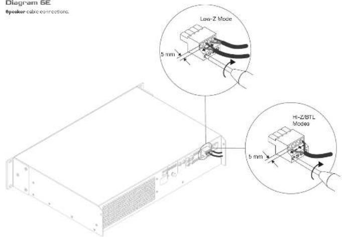
Diagram 6F
GPIO cable connections.
natural_image
Diagram of a server rack with an attached cable and a magnified inset showing the cable being inserted (no text or symbols present)7. Operation
Once all connections have been made and configuration options selected, the AMP-2500 DSP amplifier is ready for use. If an input signal above 60dB is present on any input, the front panel [Input] and [Standby] indicators will illuminate green to indicate normal amplifier operation. Audio will be heard from any connected speakers.
NOTE
The AMP 0500 DSP amplifier will be default not wake from Standby Mode unless an input signal is present, a network "ON" command is received, or an external standby switch (or 12V trigger) is operated. Standby behaviour can be configured via the [Power Management] menu of the AMP CONFIGURATOR [Settings] Tab
Amplifier outputs will mute if no input signal is present for 5 minutes, and the amplifier will switch automatically to Standby Mode if no signal is present or any input for more than 15 minutes. Alternative standby and mute delay times can be selected via the AMP CONFIGURATOR [Settings] Tab. Amplifier cooling fan speed is temperature controlled. The fan will switch off when the amplifier enters standby mode.
2021
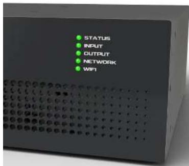
7.1 Front Panel Indicators
AMP-2600 DSP amplifier front panel indicators illuminate to indicate the following operational states:
[STATUS]
Off Main power disconnected
• Green Amplifier operational
Pulse Green Standby Mode
• Amber GPIO triggered Standby Mode
[INPUT]
Off No input signal present
- Green Signal present on one or more
inputs
• Amber Signal limiting/clipping on one or more inputs
[OUTPUT]
Off No input signal present
- Green Signal present on one or more outputs
• Amber Signal limiting/clipping on one or more output - Red One or more channel pair is in overload/protection mode
[NETWORK]
Off No ethernet network detected
Green Ethernet network detected
[WIFI]
OFFWIFI disabled
Green WiFi enabled
7.2 Default Reset
The AMP 2500 DSP amplifier can be returned to its default settings via either the AMP CONFIGURATOR [Settings] Tab or through the front panel power button.
To reset the amplifier using the front panel power button, follow the steps below.
- Disconnect the amplifier from main power.
- Press and hold the front panel power button while simultaneously reconnecting maine power.
- Continue to hold the front panel power button for 3 to 5 seconds as the amplifier restarts.
The amplifier will restart with all settings at their baseline state. Any previously configured settings or functional profile data will be deleted.
8. Advanced Configuration
In addition to the installation of DALI functional profiles described in Section 0.3 of this manual, the DALI-PHANTOM OIAMP-2500 DBP can be further configured to meet a variety of more advanced installation requirements. The advanced configuration options are described in the following paragraphs.
Adjustment of AMP-2500 DSP advanced configuration parameters demands specialist knowledge and should only be carried-out by appropriately qualified audio technicians.
Begin by connecting the AMP-2500 DSP to a network sealed device such as a smart phone, tablet or computer. Open a web browser on the connected device and browse to the DALI PHANTOM OF AMP CONFIGURATOR web interface. The AMP CONFIGURATOR Dashboard, illustrated in Diagram 8A, will be displayed.
NOTE
AVP-2000 DSP network connection is described in Section b.2 of this manual.
The [Dashboard] displays the amplifier status, output zones and the configuration menu tabs. It also enables immediate access to volume control. The advanced functions available under each configuration menu tab are described in the following paragraphs:
8.1 AMP CONFIGURATOR [Input] Tab
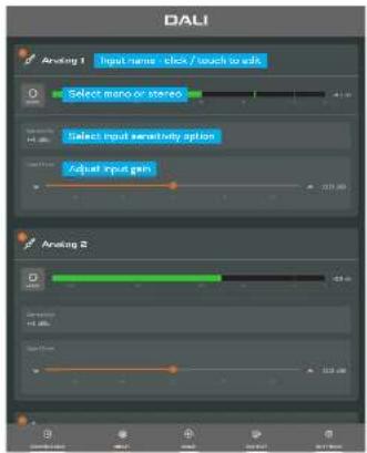
The [Input] Tab provides naming, mono/stereo selection, sensitivity, and gain trim for each amplifier input channel. An internal pink noise source, provided for system testing and set up, can also enable or disabled, and adjusted for gain via the [Input] Tab. Diagram 8B illustrates the [Input] Tab.
NOTE
When adjusting input gain, the input level display should remain green. If it displays red, the input gain should be reduced.
Diagram 8A
AMP CONFIGURATOR [Dashboard] display.
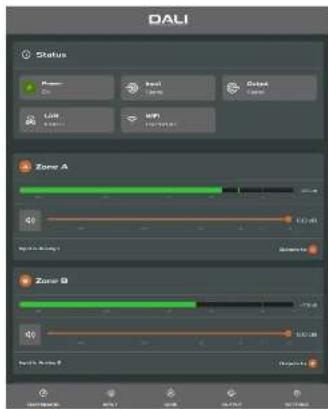
Diagram 8B
AMP CONFIGURATOR [Input] Tao display.
22 23
8.2 [Zone] Tab
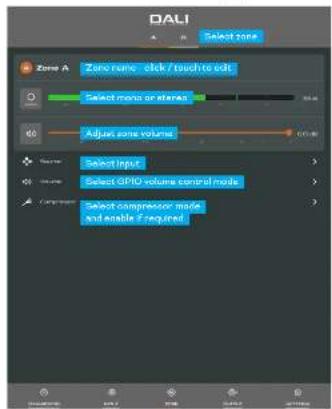
The [Zone] Tab enables installation zones to be defined and named, and provides access to further sub-menus. Zone might be lounge or dining areas for example, or different rooms in the home. For all [Zone] Tab menus, the installation zone under configuration is selected by highlighting one of the zone identifiers (A, or B) as the top of the page. Diagram 8C illustrates the [Zone] Tab.
- The [Source] menu option enables inputs to be assigned to zones.
- The [GPIO Volume Control] option enables external volume control to be applied to individual zones. The GPIO configuration menu can be found under the [Settings] Tab
- The [Compressor] option enables default or custom signal compression to be applied to individual installation zones.
Diagram BC
AMP CONFIGURATOR [Zone] Tab display.
NOTE
Compression can be useful to reduce the volume difference between loud and quiet audio materials. The lower the compression threshold is set, the more the difference between loud and soft will be reduced. The overall zone volume may need to be increased when compression is used. The default compression parameters are appropriate for most installations.
Diagram 8D
AMP CONFIGURATION [Output] Tab close to
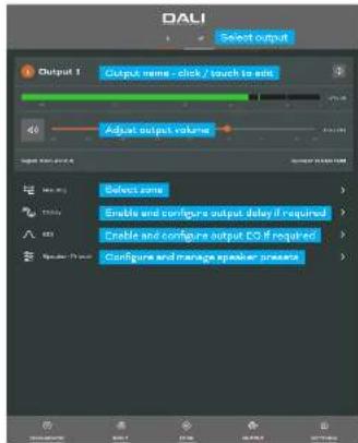
Diagram BE
AMP CONFIGURATOR [Speaker Preset] perimeters.
8.3 [Output] Tab
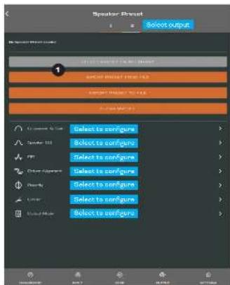
The [Output] Tab enables speaker outputs to be named and provides access to further sub-menus. For all [Output] Tab menus, the amplifier output under configuration is selected by highlighting one of the output identifiers (1 or 2) at the top of the display. The [Output] Tab also enables Speaker Preset configurations to be created, exported, imported or cleared. Diagram 8D illustrates the [Output] Tab.
- The [Routing] menu enables zones to be assigned to amplifier outputs.
- The [Delay] menu enables delay to be applied to individual amplifier outputs.
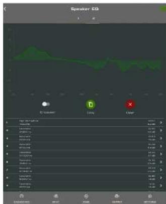
- The [Speaker EQ] menu enables parametric equalization to be applied to individual amplifier outputs. Equalizer settings configured for one amplifier output can be copied and applied to other outputs.
- The [Speaker Preset] menu enables a set of speaker parameters to be adjusted, and speaker preset configurations to be created.
- Speaker Presets can be simply applied to the selected amplifier output or imported, chosen from a library, exported or cleared. The preset configurations can include any or all of the parameters described in
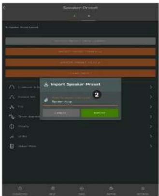
Diagram 8F
AMP CONFIGURATOR [Speaker Preset]Import
Section 7.3.4 and can be locked to prevent inadvertent modification. Diagrams 8E to 8H illustrate the application of speaker presets.
- Speaker Preset data provided by third parties for use with specific speakers can be imported and applied to amplifier outputs. To import speaker preset parameters follow the steps described below and illustrated in the diagrams.
1 Select either the [IMPORT PRESET FROM FILE] or [SELECT PRESET FROM LIBRARY] option from the [Speaker Preset] menu. If no import option is visible, select [CLEAR] to delete any existing speaker preset data.
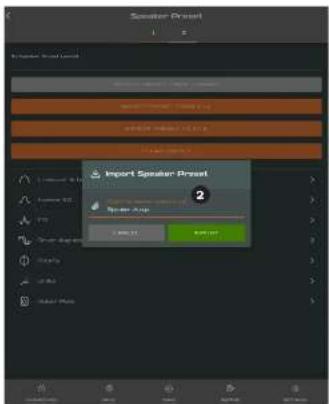
2 Select the appropriate 'top' format speaker preset data file to import from either a library or a computer folder. The preset data will be applied to the selected amplifier output as soon as the file import is complete.
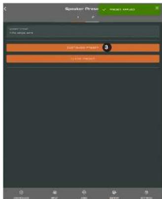
3 If the Speaker Preset data requires modification it can be customized by selecting the .CUSTOMIZE.PRESET option
Diagram 8G
AMP CONF CURATOR [Speaker Preset] applied
NOTES
The number of individual outputs available for configuration will depend on the AYP-2500 DSP input, zone and output mode configuration.
Routing for zones specified as stereo will automatically offer three output options: [Left], [Right] or [Sum] (summed mono). The summed mono signal can potentially be used to power a mono subwoofer from a stereo source.
AMP 2500 DSP Speaker Proseta and distinct from Functional Profiles in that they don't include amplifier input, zone or signal routing parameters.
The [SELECT PRESET FROM LIBRARY, option will be unavailable if no speaker preset libraries have been created. Speaker preset library creation and management is described in Section 7.5.
If an imported Speaker Preset data file includes locked parameters, they will be unavailable for modification.
The AMP 2500 DGP is by default installed with the correct preset for the SUB 5-100 subwoofer. If another preset or a custom preset is desired, clear the current preset and import or create your own.
Diagram 8H
AMP CONFIGURATOR [EQ] parameters
- The [Crossover & Gain] preset menu enables high or low-pass crossover filters and gain adjustment to be applied to individual amplifier outputs.
- The [Speaker EQ] preset menu enables parametric equalization to be applied to individual amplifier outputs.
- The [FIR] preset menu amplia FIR (Finite Impulse Response) based equalization filter coefficients generated by external speaker measurement software to be imported and applied to individual amplifier outputs.
- The [Driver Alignment] preset menu enables delay to be applied to individual amplifier outputs.
- The [Polarity] project manu enables the polarity of individual amplifier outputs to be reversed.
- The [Limiter] preset menu enables signal limiting to be applied to individual amplifier outputs. Clip limiting, peak limiting and RMS limiting can be individually or collectively engaged. The Peak limiter can be set to either automatic or custom parameter values. The RMS limiter has default parameter values that can be adjusted but has no automatic option.
- The [Output Mode] preset menu enables individual amplifier outputs to be switched off or configured for Lo-Z, Hi-Z or Lo-Z DTL modes. In Hi-Z modes, a high-pass filter can also be configured and applied to the output. The number of outputs available will depend on the input setup and zone setup. For example, a two output amplifier will have two outputs available if Lo-Z mode is selected but only one output available if Hi-Z mode is selected.
NOTES
FIR coefficient files in either .csv or .txt format can be imported.
In automatic mode, the back limiter parameters adjust automatically in response to Crossover & Gain high-pass filter settings.
In Lo-Z BTL (bridge-tied load) mode, two amplifier output channels are combined to create a single, double power output channel.
Use of a high pass filter with Hi Z mode loudspeakers is useful to avoid the possibility of distortion caused by low frequency line transformer saturation. Begin with the default filter setting of 70Hz. If low frequency distortion is still audible, increase the frequency setting one step at a time until the distortion is no longer audible.
8.5 [Settings] Tab
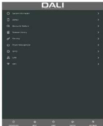
The [Settings] Tab enables miscellaneous amplification settings to be configured and installation data to be recorded. The [Settings] Tab provides access to further sub-menus. Diagram BI illustrates the [Settings] Tab
- The [System Information] menu provides text fields for the recording of installation data.
- The [Device] menu records amplifier specific information such as the model number and firmware version. A firmware update routine and identifier button can also be found under the [Device] menu.
- The [Backup & Restore] menu enables amplifier functional profiles to be downloaded to an external archive, and enables previously saved configuration files to be uploaded and adopted by the currently connected amplifier. Explained in Section 5.3.1.
-
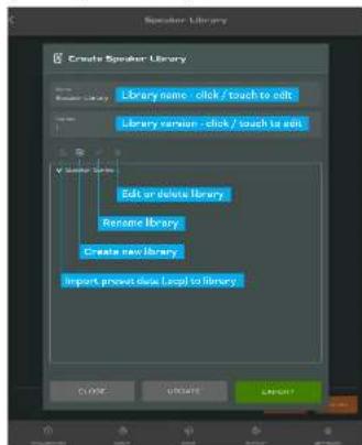
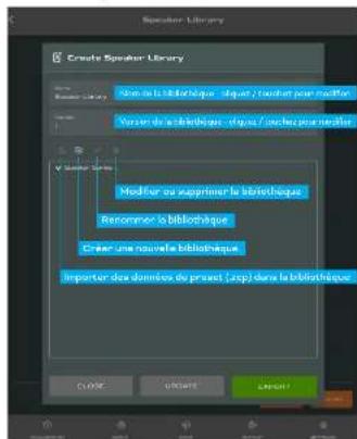
The [Speaker Library] menu enables management of speaker preset libraries. Libraries of speaker preset files (20) can be created, and existing libraries can be imported, edited or fully deleted. Diagram 8J illustrates the creation and management of speaker preset libraries.
-
The [Power Management] menu enables various automatic switch-on and standby options to be engaged. The Power Management menu also offers a United Mute function.
- The [GPIO] menu enables configuration of the multi-purpose GPIO interface pins.
- The [LAN] menu enables configuration and reset of the wired network options and parameters
- The [WIFI] menu enables configuration and reset of the wireless network options and parameters.
NOTE
The front panel power switch will override any power management settings.
Diagram BI
AMP CONFIGURATOR [Settings] Tab menu
Diagram 8J
AMF CONFIGURATOR [Settings] Tao marl Speaker Library Creation and Management
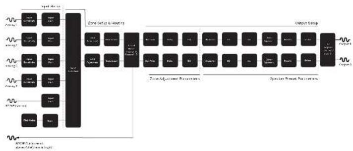
8.6 Setup and Signal Routing
Thanks to the DALIPHANTOM CI AMP CONFIGURATOR the AMP-2500 DSP amplifier offers considerable versatility in terms of sources, signal routing, installation zones and output modes. Inputs can be freely assigned to installation zones, and those zones assigned freely to the available amplifier outputs in either 1.6 Z or Hi Z modes.
This versatility enables, for example, different inputs to be routed to different output zones.
The following paragraphs describe and illustrate the recommended procedure for configuring input, zone and output routing. A general signal flow schematic is also illustrated in Diagram 8K.
8.7 Input Setup
Open the configuration Dashboard and select the [Input] Tab. The [Input] Tab is shown in Diagram 8B.
• To edit default input names simply select and type in the Input Name field.
- Define a mono or stereo input by selecting the appropriate option. Defining a stereo input will reduce the total number of discrete inputs available.
- Select an input sensitivity option from the [Senitivity] drop-down menu +14dB, 4dB, +0dB and 'Microphone' options are available. Generally the +14dB or +0dB options are appropriate for 'professional audio' source hardware with balanced outputs, while the 10dB option is more appropriate for 'consumer audio' source hardware with unbalanced outputs. The [Microphone] option provides the significantly greater sensitivity required for microphone.
NOTE
Only dynamic microphones are suitable for connection. Phantom power for condenser microphones is not provided.
- If necessary, adjust the input gain using the slider or up/down icons. Gain adjustment is intended to be used for fine output level adjustment following initial use.
Diagram BK
Amplifier Signal Flow Schematic
flowchart
graph TD
    A["Input Module"] --> B["Zone Setup & Loading"]
    B --> C["Zone Adjustment Parameters"]
    C --> D["Output Group"]
    D --> E["Final Output"]

    subgraph Zone_Adjusted_Parameters
        F1["Input Module 1"]
        F2["Input Module 2"]
        F3["Input Module 3"]
        F4["Input Module 4"]
        F5["Input Module 5"]
    end

    subgraph Operational_Purchased_Positions
        G1["Input Module 1"]
        G2["Input Module 2"]
        G3["Input Module 3"]
        G4["Input Module 4"]
        G5["Input Module 5"]
    end

    H["Output Module"] --> I["Final Output"]
28.20
8.8 Zone Setup & Routing
Open the configuration Dashboard and select the [Zone] Tab. The [Zone] Tab is shown in Diagram 8C
- Select the zone to be configured. The number of zones available and their channel format (stereo or mono) will depend on the amplifier input setup and output mode (Lo-Z or Hi-Z). For example, a two output amplifier can have the following zone configurations:
- 1x stercio Le Z zare
- 2 x mono Lo-Z zones
- 1x mono I II-Z zone
- 1x mono Lo-Z BTL zone
- Name zones by typing in the Zone Name field.
- Adjust the zone volume if required by using the slider.
- Define a mono or stereo zone by selecting the appropriate option. Defining a stereo zone will reduce the total number of further zones available.
- Specify an input for the zone by selecting from the drop-down menu. Selecting a stereo input for a mono zone will automatically sum the stereo channels to mono.
NOTES
When configured in Lo-Z DTL mode or Hi-Z mode, the AMF-2500 DSP amplifier operates in 'bridged' mode where the output of two channels is combined. This means that the number of output channels available in these modes is half that available in Lo-Z mode.
Mono signals might be mono at source, created though combining the left and right channels of a stereo signal (summed mono) or treating the left and right channels of a stereo signal independently (split mono).
8.9 GPIO Setup and Connection
The AMP-2500 DSP amplifier provides a GPIO socket that enables remote control of volume, standby, mute and trigger functions. The GPIO connector pin functions are described in the [GPIO] Settings menu illustrated in Diagram BL. The connection of GPIO based remote volume control and standby/mute are illustrated in Diagram 8M and Diagram 8N respectively.
NOTES
The GPIO connector must not be used for any unintended purpose. Amplifier damage may result from incorrect use of GPIO.
Shielded cable must be used when connecting standby switches and potentiometers via GPIO.
GPIO Pin 9 has a low output impedance and is able to supply a maximum current of 10mA.
GRID Pin 1 and Pin 3 both offer ground connections. Pin 1 is connected directly to the amplifier chassis. Pin 3 is connected to the chassis via a 220 Ohm resistor. The "soft ground" connection of Pin 3 is potentially useful for managing ground loops that may cause audible hum.
Diagram 8M
Potentiometer connections for remote volume control via CPIO.
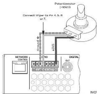
Diagram BL
AMP CONFIGURATOR [GPIO] Setting Menu
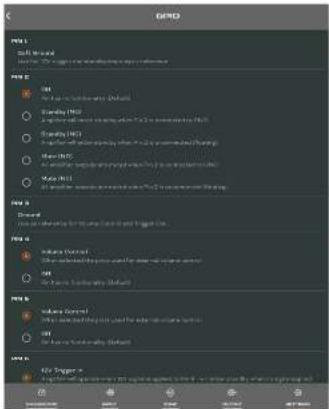
Diagram GE illustrates use of the GPIO connector
9. Specifications
| Frequency range /2 Hz - 20 kHz | [Hz, 65 dB, 80 kHz, 3 aR before rated power] |
| Connection input(s) 4x Awing unlabeled, PCA | |
| 4x Analog balanced,urobock connector | |
| 1x R/2 x R, RCA | |
| Input impedance 100Ohm | |
| Output channels: 2 x 1 x 2 speaker (4 - 20 ohm) | |
| 1 x 1 x 2 speaker (10V / 100V) | |
| 1 x 1 x 2 in digital output, RCA | |
| Maximum speaker cable cross section 2 mm ^2 / AW9.1x (Euroblock/ Plasor in" standard) | |
| Output power @ 2 ohm 2 x 500 W (RF) | |
| > (RF) mA | |
| Output power @ 4 ohm 2 x 500 W (SE) | |
| 1x 1000 W (ESTL) | |
| Output power @ 8 ohm 2 x 900 W (RF) | |
| 1 x 1000 W (ESTL) | |
| Output power @ 70V 1 x 1000 W (H I) | |
| Output power @ 100V 1 x 1000 W (IETL) | |
| Total system power 1000 W | |
| Output voltage -15 Vrms (10E) - 80 Vrms (11U) | |
| 70/100V, H I | |
| Output circuitry - MAO ^TM Class D full bandwidth PWM modulator with ultra low disorder | |
| Signal to noise-nozzle x 20 dB | [A weightless, 20 Hz, 20 kHz, 8 GHz] |
| THD+N (typical) C100% | [pp] > -20 kHz, 80 kHz, 3 dB (double rated power) |
| Other features: Smart circuit protection | |
| DC protection | |
| Unconvolge protection | |
| temperature protection | |
| Download protection | |
| Rack mounting | |
| Power supply | UREO ^TM universal mode switching mode power supply and Power Factor Correlation (SFC) and standby converter |
| Operating temperature | C < 10°C |
| Operating voltage/ frequency | Universal mode |
| 100 V, 240 V, 50 Hz, 60 Hz | |
| Power ratings | 1/2 F = 30 W/20 Vcc and 200 Vcc |
| Standby consumption | < 10 kW |
| Outer dimensions (H x W x D) 88 x 440 x 920 mm | 3/45 x 7.32 x 12.60 inches |
| Weight | 5W kg |
| 10 lb | |
| Shipping weight | 7.5 kg |
| 16 lb | |
| Accessories | 2x Low channel subrained input connection |
| 4x Two channel speaker output consector | |
| 4x GPIO socket connector | |
| 4x High power cable | |
| 4x low access transformer | |
| 2x track mount cars (mounted) | |
| Optional accessories | DAI CONNECT BGP2000 (speaker cable), DAVI CONNECT BGP2000 (speaker cable) |
FSE - conventional, single ended output mode BTL - bridge tied load output mode
DALI
DALI PHANTOM CI AMP-2500 DSP
42 43
natural_image
Line drawing of a server rack connected to a cable, with an inset showing a close-up of the internal components (no text or symbols visible)natural_image
Technical line drawing of a server rack with cable connections and a magnified inset showing internal wiring (no text or symbols)48 49
Abbildung 6E

natural_image
Illustration of a server rack with a cable inserted, showing internal wiring and a close-up of the cable being inserted (no text or symbols present)7. Betrieb
52 53
Register here, Input ^4 sec AMP CONFIGURATION
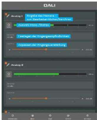
Abbildung 8J
GPIO Settings Mar0 sec AMP CONFIGURATOR
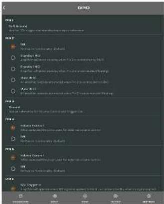
Abbildung AN
THD+N (typich) < 0.05%
1.2.1.2.3.4.5.6.7.8.9.10.11.12.13.14.15.16.17.18.19.20.21.22.23.24.25.26.27.28.29.30.31.32.33.34.35.36.37.38.39.40.41.42.43.44.45.46.47.48.49.50.51.52.53.54.55.56.57.58.59.60.61.62.63.64.65.66.67.68.69.70.71.72.73.74.75.76.77.78.79.80.81.82.83.84.85.86.87.88.89.90.91.92.93.94.95.96.97.98.99.100
GE - konverktoraler Eing-Endad-Ausgangs-odus
7273
Schéma 50
Schéma 5D
flowchart
graph TD
    A["1 x Subconverter (LFE-1)"] --> B["Multiplexer U2"]
    C["2 x Subconverter (LFE-3)"] --> D["Multiplexer U2"]
    E["INPUT 1 AND OUTPUT"] --> F["AND LUX INPUTS O=0.044"]
    E --> G["OUTPUTS O=0.044"]
    E --> H["OUTPUT"]
    E --> I["OUTPUT"]
flowchart
graph TD
    A["ANALOGINPUT"] --> B["ANALOGINPUT8"]
    B --> C["OUTPUT8"]
    C --> D["CH1"]
    D --> E["Output"]
    F["IN-AN OUTPUT"] --> G["IN-AN OUTPUT8"]
    G --> H["OUT-UT8"]
    H --> I["CH1"]
    I --> J["Output"]
4 x Subwoofer (LFE .1)
flowchart
graph TD
    A["Sub (input LFE)"] --> B["CPU"]
    B --> C["AT-ALCO INPUT"]
    B --> D["OUTPUT"]
    C --> E["1"]
    C --> F["2"]
    C --> G["3"]
    C --> H["4"]
    C --> I["5"]
    D --> J["输出"]
    style A fill:#f9f,stroke:#333
    style B fill:#ccf,stroke:#333
    style C fill:#cfc,stroke:#333
    style D fill:#fcc,stroke:#333
    style E fill:#ffc,stroke:#333
    style F fill:#cfc,stroke:#333
    style G fill:#cfc,stroke:#333
    style H fill:#cfc,stroke:#333
    style I fill:#cfc,stroke:#333
78
natural_image
Line drawing of a server rack connected to a cable, with an inset showing a close-up of the internal components (no text or symbols visible)natural_image
Technical line drawing of a server rack with cable connections and an inset showing a plug inserted into a socket (no text or symbols)natural_image
Illustration of a server rack with an attached cable and a magnified inset showing the cable being inserted (no text or symbols present)7. Opération
B2 B3
84 85
8.3 Onglet Output
REMARQUES:
Schéma BJ
Manu d'onglet Settings com AMP CONFIGURATOR Speaker Library Creation and Management
Provenation controls in temperature
natural_image
Line drawing of a server rack connected to a cable, with an inset showing a close-up of the internal components (no text or symbols visible)natural_image
Technical line drawing of a server rack with cable connections and an inset showing a plug inserted into a socket (no text or symbols)108 100
Diagrama 6E
natural_image
Illustration of a server rack with a cable inserted, showing internal wiring and a close-up of the cable being inserted (no text or symbols present)7. Funcionamiento
112 113
Diagrama 8F
Importment in Speaker Preset and AMP CONFIGURATOR
NOTAS
Diagrama BJ
Diagrama 8N
技术与安全须知
图 5C
133
6.连接
natural_image
Line drawing of a server rack connected to a cable, with an inset showing a close-up of the internal components (no text or symbols visible)图 6D
平衡推拉输入线或连接。
natural_image
Technical line drawing of a server rack with cable connections and a magnified inset showing internal wiring (no text or symbols)138 139
图6E