A1101 - Video Intercom DoorBird - Free user manual and instructions
Find the device manual for free A1101 DoorBird in PDF.

| Brand | DoorBird |
| Model | A1101 |
| Product Type | IP Indoor Monitor (video intercom) |
| Dimensions (H x W x D) | 179.5 x 115 x 25 mm |
| Power Supply | 15 - 48 V DC (max. 15 W) or PoE IEEE 802.3af Mode-A |
| Power Consumption | 5 W |
| Display | 4" color capacitive touch LCD, resolution 800 x 480 px, IPS |
| Audio | Wideband speaker and microphone, noise and echo reduction (AEC, ANR), two-way streaming |
| Network | Ethernet PoE 802.3af Mode-A, WiFi 802.11 b/g/n 2.4 GHz |
| Connections | LAN/PoE (T+, T-, R+, R-), 2 digital inputs (0 V, 0 A NO), 3 bistable lock relays (max. 24 VDC/VAC, 1 A), 15-48 V DC input |
| LEDs and Buttons | Control LED (power/network), LED status bar, touch buttons: Open door, Favorites, Mute, Menu, Activate listen and speak |
| Software Features | DoorBird app (iOS/Android), WiFi configuration, remote access, push notifications, visit history, motion detection (activatable) |
| Security | Bank-level encryption, no port forwarding or DynDNS, data center in the EU |
| Mounting | Surface mount on wall bracket (indoor), optional table stand A8003 |
| Operating Conditions | 0 to +55°C, relative humidity 0% to 85% (non-condensing) |
| Certifications | CE, FCC, IC, RoHS, IP50 |
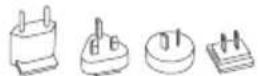
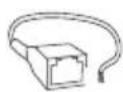
| Package Contents | Indoor monitor, mounting bracket, RJ45 adapter, power adapter with 4 country adapters, quick start guide with digital passport, installation manual, small parts |
| Optional Accessories | Table stand A8003, 2-wire PoE+ converter A1072, PoE injector A1091, DIN rail power supply, etc. |
| Warranty | See www.doorbird.com/en/warranty |
Frequently Asked Questions - A1101 DoorBird
User questions about A1101 DoorBird
0 question about this device. Answer the ones you know or ask your own.
Ask a new question about this device
Download the instructions for your Video Intercom in PDF format for free! Find your manual A1101 - DoorBird and take your electronic device back in hand. On this page are published all the documents necessary for the use of your device. A1101 by DoorBird.
USER MANUAL A1101 DoorBird
IP Video Indoor Station
A1101 Series

Seite 18-32
Read these instructions carefully before starting to use any components. Keep the manual so you can refer to it at a later date if required. If you hand over the device to other persons for use, please hand over the operating manual as well.
You can always find the most up-to-date version of the installation manual on www.doorbird.com/support
To make things easier we use the term "device" for the product "DoorBird IP Video Indoor Station A1101" and "mobile device" for a smartphone or tablet.
Liability
Every care has been taken in the preparation of this document. Please inform Bird Home Automation GmbH of any inaccuracies or omissions. Bird Home Automation GmbH cannot be held responsible for any technical or typographical errors and reserves the right to make changes to the product and manuals without prior notice. Bird Home Automation GmbH makes no warranty of any kind with regard to the content of this document, including, but not limited to, the implied warranties of merchantability and fitness for a particular purpose. Bird Home Automation GmbH shall neither be liable nor responsible for incidental or consequential damages in connection with the furnishing, performance or use of this material. This product is only to be used for its intended purpose.
Equipment Modifications
This equipment must be installed and used in strict accordance with the instructions given in the user documentation. This equipment contains no components that require service by the user. Unauthorized equipment changes or modifications will invalidate all applicable regulatory certifications and approvals.
Symbols used

Danger: Indicates a hazardous situation which, if not avoided, will result in death or serious injury.

Warning: Indicates a hazardous situation which, if not avoided, could result in death or serious injury.

Caution: Indicates a hazardous situation which, if not avoided, could result in minor or moderate injury.

Notice: Indicates a situation which, if not avoided, could result in damage to property.

Important: Indicates significant information which is essential for the product to function correctly.

Note: Indicates useful information which helps in getting the most out of the product.
IC Statement
This device contains licence-exempt transmitter(s)/receiver(s) that comply with Innovation, Science and Economic DevelopmentCanada's licence-exempt RSS(s). Operation is subject to the following two conditions:
(1) This device may not cause interference. (2) This device must accept any interference, including interference that may cause undesired operation of the device.
The term "IC:" before the certification/registration number only signifies that the Industry Canada technical specifications were met.
This product meets the applicable Industry Canada technical specifications.
This transmitter must not be co-located or operating in conjunction with any other antenna ortransmitter. This equipment should be installed and operated with a minimum distance of
Changes or modifications not expressly approved by the party responsible for compliance could void the user's authority to operate the equipment.
This equipment has been tested and found to comply with the limits for a Class B digital device, pursuant to Part 15 of the FCC Rules. These limits are designed to provide reasonable protection against harmful interference in a residential installation. This equipment generates uses and can radiate radio frequency energy and, if not installed and used in accordance with the instructions, may cause harmful
interference to radio communications. However, there is no guarantee that interference will not occur in a particular installation. If this equipment does cause harmful interference to radio or television reception, which can be determined by turning the equipment off and on, the user is encouraged to try to correct the interference by one or more of the following measures:
-- Reorient or relocate the receiving antenna.
-- Increase the separation between the equipment and receiver.
-- Connect the equipment into an outlet on a circuit different from that to which the receiver is connected.
-- Consult the dealer or an experienced radio/TV technician for help
This device complies with part 15 of the FCC rules. Operation is subject to the following two conditions (1) this device may not cause harmful interference, and (2) this device must accept any interference received, including interference that may cause undesired operation.
This equipment complies with FCC radiation exposure limits set forth for an uncontrolled environment. This equipment should be installed and operated with minimum distance 20cm between the radiator & your body.
Please observe the warnings and safety instructions in our accompanying booklet:
https://www.doorbird.com/downloads/warnings.pdf
COMPONENTS
natural_image
Isometric line drawing of a rectangular electronic device with a grid and circular button (no text or symbols)

natural_image
Pure architectural floor plan lines without any text, numbers, or symbols1x Quickstart guide with Digital Passport
1x Device 1x Drilling template installation manual

natural_image
Pure technical line drawing of a mechanical part outline (no text or symbols)1x Mounting bracket

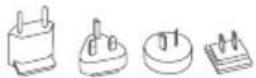
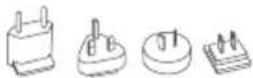
1x Power supply unit (mains adaptor) with up to four country-specific adaptors
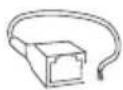
1x RJ45 Adapter
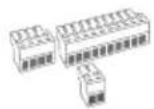
3x Screw connection terminal plugs
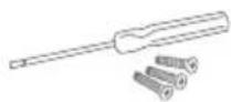
Small parts
DEVICE
Front

Back
1) Gorilla® Glass
2) Touch Display
3) Button "Open door"
4) Button "Favourite"
5) Button "Mute"
6) Button "Menu"
7) Button "Enable listen and talk"
8) Speaker Large-sized broadband speaker
9) LED Status Bar
To visualize ring events etc.
10) Diagnostic-LEDs
To visualize the current status of the device
11) Microphone
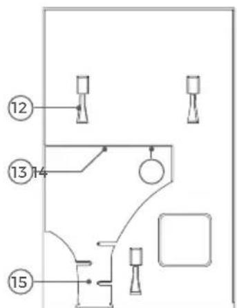
12) Mounting points
To mount the device on the mounting bracket
13) Screw connection terminal
14) Setup button (SET)
of the device, to e.g. configure the WiFi interface
of the device using the DoorBird App
15) Cable clamp
VIDEOS
Need help with the installation? Be sure to watch our installation videos which can be found on www.doorbird.com/support
Each individual step of the installation is clearly documented in the videos.
INSTALLATION
All the steps below should be carried out carefully by a competent adult, taking into consideration any applicable safety regulations. Please contact us directly or seek the advice of a competent specialist.

Please ensure that all wires used for the installation are undamaged along their entire length and approved for this type of use.
Network speed and network components
Please ensure that the upload speed of your Internet connection is at least 0.5 Mbps. The user experience is only as good as your network speed, network stability and quality of your network components, such as your Internet Router and WiFi access points or WiFi repeaters. Please also make sure that your network components are no older than two years, have been manufactured by a well-known manufacturer, and have the latest firmware installed.
Should these requirements not be fulfilled, it may occur, for example, that the performance of audio and video is poor or push notifications are delayed or do not arrive on your smartphone or tablet at all.
Requirements:
High-speed Internet (via landline): DSL, cable or optical fibre
Network: Ethernet, with DHCP
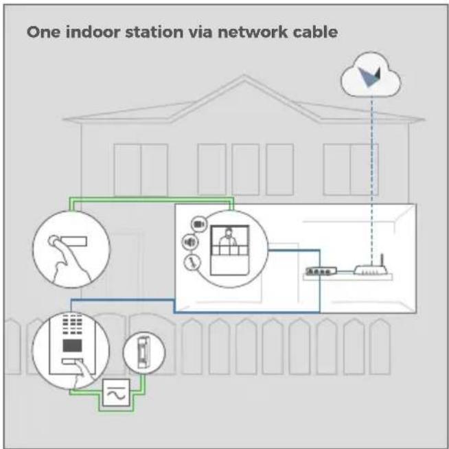
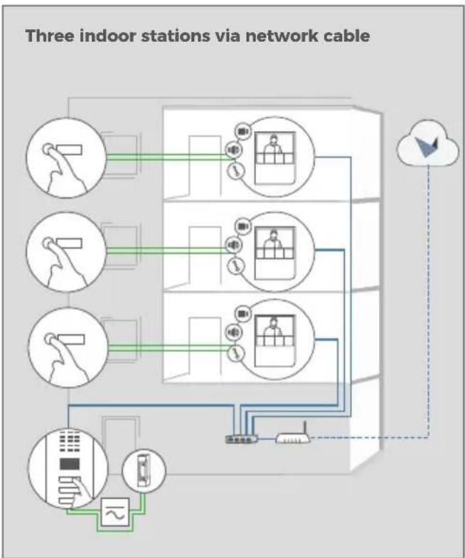
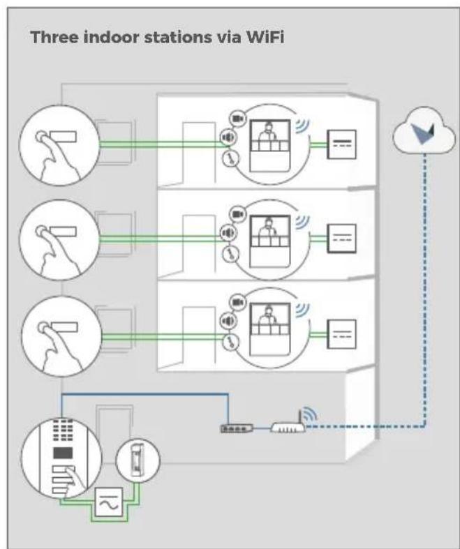
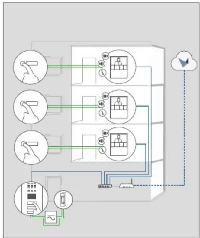
INSTALLATION EXAMPLES
flowchart
graph TD
    A["One indoor station via network cable"] --> B["Device 1"]
    A --> C["Device 2"]
    A --> D["Device 3"]
    A --> E["Device 4"]
    A --> F["Device 5"]
    B --> G["Mobile Device"]
    C --> H["Mobile Meter"]
    D --> I["Mobile Phone"]
    E --> J["Mobile Tablet"]
    F --> K["Mobile Display"]
Electric door or gate opener. Can be secured via DoorBird I/O Door Controller if required (remote safety relay)
flowchart
graph TD
    A["Smartphone"] --> B["Mobile Device"]
    B --> C["Cloud"]
    D["Smartphone"] --> E["Mobile Device"]
    E --> F["Mobile Device"]
    G["Cloud"] --> H["Network"]
    H --> I["User Device"]
    I --> J["Remote Control Unit"]
    style A fill:#f9f,stroke:#333
    style B fill:#ccf,stroke:#333
    style C fill:#cfc,stroke:#333
    style D fill:#fcc,stroke:#333
    style E fill:#cff,stroke:#333
    style F fill:#ffc,stroke:#333
    style G fill:#cfc,stroke:#333
    style H fill:#fcc,stroke:#333
    style I fill:#ffc,stroke:#333
    style J fill:#cfc,stroke:#333
flowchart
graph TD
    A["Mobile Device"] --> B["Device 1"]
    C["Mobile Device"] --> D["Device 2"]
    E["Mobile Device"] --> F["Device 3"]
    G["Mobile Device"] --> H["Device 4"]
    I["Mobile Device"] --> J["Device 5"]
    K["Mobile Device"] --> L["Device 6"]
    M["Mobile Device"] --> N["Device 7"]
    O["Mobile Device"] --> P["Device 8"]
    Q["Mobile Device"] --> R["Device 9"]
    S["Mobile Device"] --> T["Device 10"]
    U["Cloud Access"] --> V["Wireless Device"]
    W["Wireless Device"] --> X["Wireless Device"]
    Y["Wireless Device"] --> Z["Wireless Device"]

Power over Ethernet (PoE) Switch

Router with High-speed Internet, DHCP

Seperate power supply 15 V DC, 1 A

Seperate power supply 12 V DC, 1 A

Network cable 2-wire-cable
1
SWITCHING OFF POWER

Switch off the power to all wires leading to the assembly location, i.e. the door chime, electric door opener, power supply unit, PoE-Switch/ PoE-Injector etc.
2
DISMANTLING THE EXISTING INDOOR STATION
Should there already be an indoor station on the wall, please remove it.
3
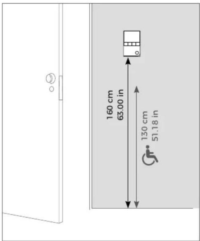
DETERMINING THE ASSEMBLY LOCATION

The device is designed for indoor-use only.
Recommended installation height: 160 cm / 63 in Recommended installation height for people with impairments / disabilities: 130 cm / 51 in
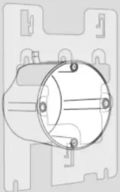
natural_image
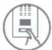
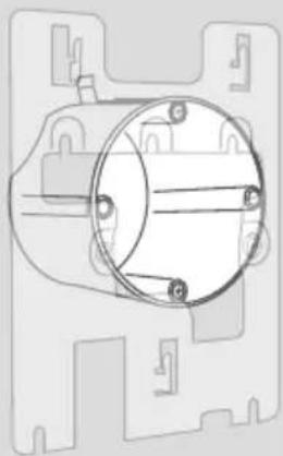
Technical line drawing of a mechanical component with mounting holes and a central cylindrical housing (no text or symbols)The mounting bracket may be used in connection with a standard 68 mm (2.68 in) hollow-wall box, which means you do not have to drill separate holes into the wall: You can use the existing screw holes of the hollow-wall box and skip STEP 4.
If there is no hollow-wall box at the assembly location: Press the drilling template of the device against the wall or ceiling at the desired installation site and mark the boreholes with a pencil. Remove the drilling template again. Ensure that no cables are to be found in the wall or ceiling behind the boreholes.
4
DOWELS
If the wall of the house is not made of wood, you should drill dowel holes 5 mm in diameter in the wall according to the drilling template and then place the dowels provided into the boreholes.
If the wall of the house is made of wood, dowels are normally not required. There are special dowels for assembling the device on an insulating wall, e.g. Fischer insulating dowels.
Please check with your insulating material manufacturer regarding which dowels they recommend.
5
NETWORK CONNECTION OPTIONS
You can connect the device to the network by either using a network cable or a WiFi 2.4 GHz connection.
OPTION 1
Network cable (recommended, maintenance free)
Install a network cable (which is plugged into a network switch / router with Internet access) from the inside of your building to the assembly location. The network cable between the assembly location and the network switch / router can have a maximum length of 80 m/262 ft (IEEE 802.3). If you must span a distance of more than 80 meters/262 feet you can put a network switch inbetween. Make sure to use a high-quality Cat.5 network cable or better and with proper shielding (Screened Foiled Twisted Pair (S/FTP or SFTP)) whereby the shield is connected to the outer metal shield of the RJ45 plug (8P8C).

As an alternative to wall mounting, you can also mount the device on a table stand (DoorBird A8003 Table Stand for IP Video Indoor Station A1101).

If you must drill holes in a wall, insert screws into a wall or lever up a wall, ensure that no cables or mains (gas, water, etc.) are to be found in the wall.

If you have only two wires available at the assembly location, you may use the "DoorBird 2-Wire Ethernet PoE+ Converter A1072", sold separately. It allows you to transfer network data (Ethernet) and power (PoE) with a simple two-wire cable over long distances. For example, existing buildings with a simple two-wire bell wire can be equipped with network technology without having to retrofit any network cables.
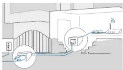
natural_image
Diagram of a smart home control system with connected devices and a staircase (no text or symbols)
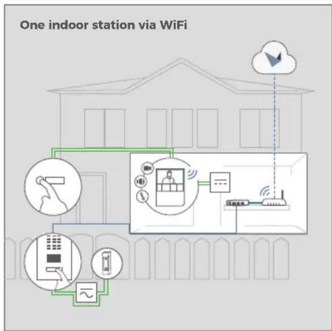
OPTION 2 WIFI 2.4 GHz
When using WiFi please make sure you have a good WiFi signal at the assembly location of the device. You can increase the WiFi signal by using so called "WiFi repeaters", which can boost your WiFi signal. You should install such a WiFi repeater close to the assembly location of the device, typically inside your home and close to the device.
6
PREPARE POWER SUPPLY
The device does not have a battery as power supply, therefore, choose one of the following options.
OPTION 1
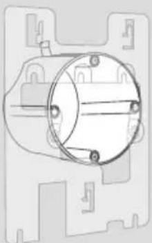
Power supply using the power supply unit (mains adaptor)
To power the device using the provided mains adapter, 2 insulated wires are required. The power supply unit has a 300 cm (9.8 ft) long cable with two insulated wires. The network connection is then established via a network cable or alternatively via WiFi.

Do not plug the power supply unit into the wall socket yet.
Only use the power supply unit (see "OPTION 3") provided along with the device, or a DIN-rail power supply unit that you can obtain from us separately, since this has been specially stabilized electrically and is equipped with an integrated audio interference reduction device. Other power supply units may destroy the device or cause poor transmission quality. The warranty automatically expires if you use a different power supply unit.
The power supply unit is plugged into a wall socket inside your house (Step 10), usually where the two wires from your assembly location come out of the wall in the interior of the house.
OPTION 2
Power supply and network connection using PoE (Power over Ethernet)
To power the device via a PoE-Switch (e.g. D-Link DGS-1008P) or PoE-Injector (e.g. DoorBird Gigabit PoE Injector A1091), use a CAT.5 cable or higher in accordance with the PoE standard IEEE 802.3af Mode A.
A CAT.5 cable or higher must be used for this purpose, as network signals can only be transmitted over completely insulated, shielded and twisted cables. If you use PoE as a source of power, the four wires for PoE then simultaneously form the data line. The device will not start if your PoE-Switch/PoE-Injector does not support the PoE Standard IEEE 802.3af Mode A. Please check www.doorbird.com/poe for known incompatibilities.

For reasons of network stability, we principally recommend using a network cable, as WiFi is sensitive to interference (range, house walls acting as shields, reliability of performance, third party WiFi networks, wireless transmitters causing interference in the area, etc.).

The provided mains adaptor is only capable to power one device. It is not designed to power multiple devices simultaneously.
If you must power more than one device with one power supply, we recommend to use a PoE-Switch with PoE Standard IEEE 802.3af Mode A or an appropriate DIN rail power supply (see "OPTION 3").

The provided mains adapter is not outdoor-ready, it is for indoor-use only.

If you must power more than one device with one power supply, we recommend to use a PoE-Switch with PoE Standard IEEE 802.3af Mode A or an appropriate DIN rail power supply (see "OPTION 3").

Do not combine the power supply from the power supply unit (mains adaptor) with the power supply via PoE.
You can find further information about PoE here: www.doorbird.com/poe

- Disconnect the PoE-Switch or PoE-Injector from the power grid.
- Place the network cable in the installation site of the device.
OPTION 3
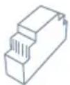
Power supply using a DIN rail power supply unit
Alternatively to the mains adapter, we offer DIN rail power supplies in our online shop, which can be installed by a specialist. The network connection is then made via a network cable or alternatively via WiFi.
Planning information to power multiple devices with a single DIN rail power supply unit
You must plan the cabling for the DIN rail power supply of the devices carefully, if you want to install more than one device in your building with a single DIN rail power supply unit.
The device has a power consumption of 5 Watt and an input voltage range from 15 to 48 VDC.
Each cable / wire has a specific load limit and loop resistance and power loss for physical reasons. The planning of the cabling, maximum number of devices and power supply depends on this. The following information will help you to plan the power supply installation in the building.

Please calculate the maximum number of devices and the power supply carefully, matching to the wire diameter and cable length. Wrong calculation and installation can lead to overheating, damage, electrical short and fire.
If shielded cables are used, the shielding should be connected to each other.

Theoretically (not recommended by us!), an unshielded, but over the whole length (max. 80 m/262 ft) twisted bell wire with two pairs of wires (first twisted pair of wires: "T+, T-", second twisted pair of wires "R+, R-") can be used for the network and PoE transmission as an alternative to a Cat.5 network cable or better. This is comparable to a Cat.3 network cable. In this case, however, we cannot guarantee the data throughput or the stability of the network connection and power supply; this must be measured and checked on site by qualified personnel over several hours (network data is transmitted at high frequency, therefore a shielded Cat.5 network cable twisted in pairs or better must normally be used).

If you must power more than one device with one power supply, we recommend to use a PoE-Switch with PoE Standard IEEE 802.3af Mode A or an appropriate DIN rail power supply.

The wire diameter is the inner metal core only, not the inner metal core plus the jacket.

Often more than two wires are available on-site for the connection of an indoor station. The maximum current can be doubled to increase the maximum number of installable devices by using two wires for one core. In this case, the two wires must be twisted at both ends. The applied voltage must not exceed 48 VDC.
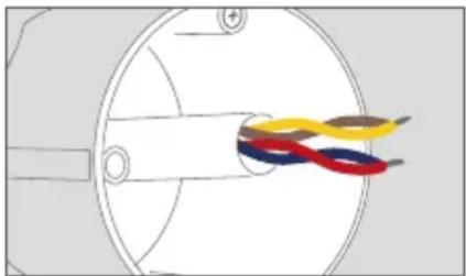
natural_image
Diagram of a cable or wire connection inside a cylindrical device, showing colored bands (no text or symbols)INFORMATION FOR PLANNERS OF NEW BUILDINGS
If you know how many devices must be installed and you know the length of the cables, you can check the following chart to see which wire diameter is required.
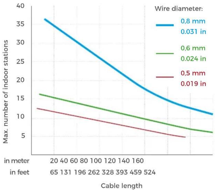

The following scenario is calculated and visualized in a chart under the worst-case scenario that all devices are connected to the rearmost end of cable in the building. In practice, the devices are distributed more or less evenly over the cable length / floors.
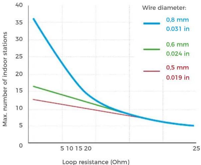
INFORMATION FOR PLANNERS OF EXISTING BUILDINGS
The length of the cables in existing buildings is often unknown and can only be roughly estimated. The diameter of the wires and the loop resistance (ohm) are known or at least easy measurable. This makes it possible to determine the maximum number of devices that can be connected to a single wire pair.
line
| Loop resistance (Ohm) | Wire diameter: 0.8 mm | Wire diameter: 0.6 mm | Wire diameter: 0.5 mm | | --------------------- | --------------------- | --------------------- | --------------------- | | 0 | 36 | 16 | 12 | | 5 | 25 | 14 | 10 | | 10 | 18 | 12 | 9 | | 15 | 12 | 10 | 8 | | 20 | 8 | 8 | 7 | | 25 | 5 | 5 | 5 |
The following scenario is calculated and visualized in a chart under the worst-case scenario that all devices are connected to the rearmost end of cable in the building. In practice, the devices are distributed more or less evenly over the cable length / floors.

The loop resistance can easily be measured by switching off the power supply on the wires to be measured and applying a short-circuit to the lines to be measured on one side and measuring the resistance on the other side of the wires with a multimeter.
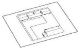
7
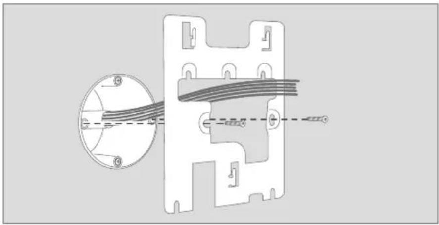
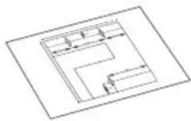
ASSEMBLE THE MOUNTING BRACKET
natural_image
Technical diagram of a mechanical component with internal cable and housing, showing cross-section view (no text or labels)Lead all cables and wires you want to connect to the device through the mounting bracket. Screw the mounting bracket to the wall.
8
CONNECTING THE DEVICE
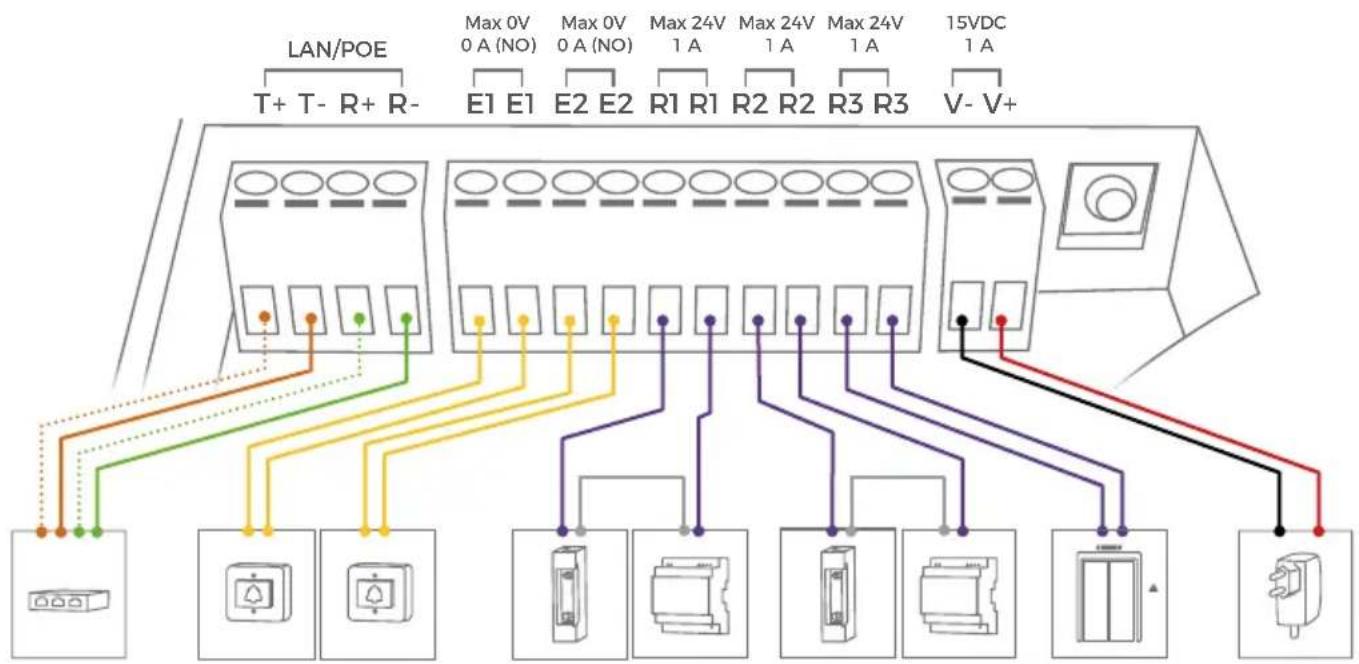
It is possible to connect the cables and wires to the device conveniently and safely via the labelled screw connection terminal. You can connect all necessary cables and wires to the device now.
NOTICE
Please remove any cables and wires from the connection ports of the device that you do not need.

For easier installation we strongly recommend to remove the plug from screw connection terminal while you connect the cables and wires.
flowchart
graph TD
    A["LAN/POE"] --> B["T+ T- R+ R-"]
    A --> C["E1 E1"]
    A --> D["E2 E2"]
    A --> E["R1 R1"]
    A --> F["R2 R2"]
    A --> G["R3 R3"]
    A --> H["V- V+"]
    B --> I["Power Supply"]
    C --> J["Switch"]
    D --> K["Rectangular Component"]
    E --> L["Rectangular Component"]
    F --> M["Rectangular Component"]
    G --> N["Rectangular Component"]
    H --> O["Rectangular Component"]
PORT DESCRIPTION
| LAN/POE The device does not have an integrated standardized RJ45 socket to ensure ...that the device rests as flat as possible on the wall.that no wall needs to be levered up.that a strong and inflexible Cat.6 or Cat.7 installation cable can be used.Use only four wires (1, 2, 3 and 6) of a standard Network cable Cat.5 or better, coming from the Internet Router/PoE-Switch/PoE-Injector.Cat.5 / Cat.6 Network cable | |
| T+ White and orange network cable wire (Number 1, Transmit Data +)T - Orange network cable wire (Number 2, Transmit Data -)R+ White and green network cable wire (Number 3, Receive Data +)R - Green network cable wire (Number 6, Receive Data -) |  |
| Cat.7 Network cable (Installation cable)T+ White network cable wire from pair "orange/white" (Number 1, Transmit Data +)T- Orange network cable wire from pair "orange/white" (Number 2, Transmit Data -)R+ White network cable wire from pair "green/white" (Number 3, Receive Data +)R- Green network cable wire from pair "green/white" (Number 6, Receive Data -)NOTICE Do not power the device simultaneously via the power supply from the power supply unit (mains adaptor) and the power supply via PoE. |  |
| E1, E1Digital input, max. 0 VDC / VAC, 0 A, e.g. for storey-call buttonNOTICE Please make sure to add no voltage on these ports. Extra voltage may destroy the device immediately. | |
| E2, E2Digital input, max. 0 VDC / VAC, 0 A, e.g. for a second storey-call buttonNOTICE Please make sure to add no voltage on these ports. Extra voltage may destroy the device immediately. | |
| R1, R1Bi-stable latching relay #1, max. 24 VDC / VAC, 1 A. Security feature: The relay keeps its state even in the case of loss of power. You can configure the default state of the relay (open/ close) via the DoorBird App. These ports can be used to connect e.g. an electric door opener or to call an elevator. The device does not supply power to the connected device. The power supply for the electric door opener must be installed separately. | |
| R2, R2Bi-stable latching relay #2, max. 24 VDC / VAC, 1 A. Security feature: The relay keeps its state even in the case of loss of power. You can configure the default state of the relay (open/ close) via the DoorBird App. These ports can be used to connect e.g. an electric door opener or to call an elevator. The device does not supply power to the connected device. The power supply for the electric door opener must be installed separately. | |
15 VDC - 15 to 48 V DC Power supply input, negative pole (-). Please connect the black wire of the power supply unit (mains adaptor) supplied with this device if you do not power the device using PoE.
Do not power the device simultaneously via the power supply from the power supply unit (mains adaptor) and the power supply via PoE.
15 VDC + 15 to 48 V DC Power supply input, positive pole (+). Please connect the red wire of the power supply unit (mains adaptor) supplied with the device here, if you do not power the device using PoE.
NOTICE Do not power the device simultaneously via the power supply from the power supply unit (mains adaptor) and the power supply via PoE.
NOTICE Please take care when connecting the cables and wires. Connecting the cables and wires the wrong way may damage the device. Wires without insulation material must not protrude out of the screw connection terminal plugs, it may lead to electrical short and damage the device.
9
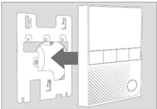
ASSEMBLE THE DEVICE TO THE MOUNTING BRACKET
natural_image
Diagram of a device with a central component and an adjacent server unit, showing internal components without any text or symbols.Put the device on the mounting bracket.
natural_image
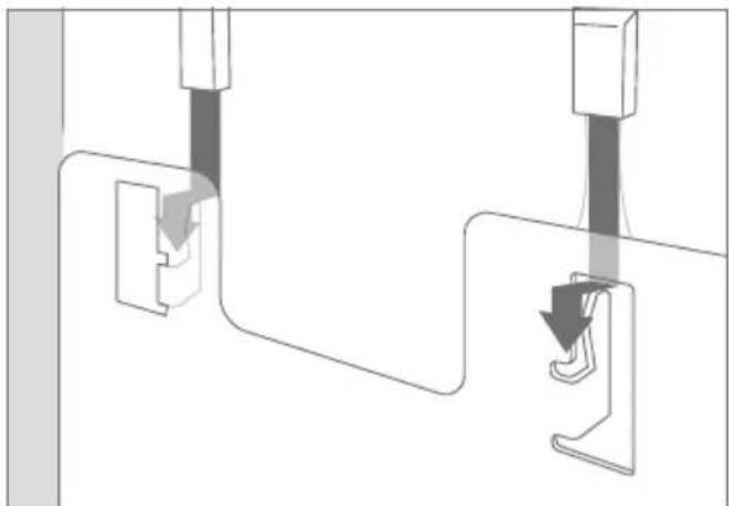
Pure mechanical assembly diagram showing two connected components with arrows indicating motion (no text or symbols)Pull the device down carefully, so it locks in place.
10
ACTIVATE THE DEVICE
If the device is to be supplied with power by a mains adapter, plug the power adapter of the device into a wall socket. If the device is to be powered via PoE, switch on the PoE-Switch/ PoE-Injector which is connected to the device. If the device is to be powered via DIN-rail power supply, switch on the DIN-rail power supply.
The Diagnostic-LEDs indicate whether the device is supplied with power. These LEDs light up in blue color immediately after you have connected the device to the power supply. The device is now ready for operation.
If the Diagnostic LED does not light up, please check the power supply. When using a wall-plug power supply and not PoE please check whether you have connected the positive pole and negative pole to the device correctly.
The device is ready for operation (booting up process, any software updates, etc.) once it has emitted a short diagnosis sound from the integrated loudspeaker. This may last for up to 5 minutes. Should you not hear a sound, please check the power supply. When using a wall-plug power

Please note that the Diagnostic-LEDs are different to the Status Bar LEDs. The LEDs used for the LED Status Bar can illuminate the Status Bar all-over and in almost any color.
supply and not PoE please check whether you have connected the positive pole and negative pole to the device correctly.
11
DOWNLOADING AND INSTALLING THE APP
Download the "DoorBird" App by Bird Home Automation onto your mobile device from the Apple App Store or Google Play Store. You can always find the most up-to-date version of the App manual on www.doorbird.com/support
If you use WiFi for connecting the device to your Internet Router, first go to the DoorBird App " > WiFi Setup" and follow the instructions.
If you have finished the WiFi setup or have connected the device to your Internet Router by means of a network cable, go to the DoorBird App “> Administration” and log in to the Administration area of the DoorBird Video Door Station (using the authentication details of the desired Video Door Station!) you would like to pair the device with (using the authentication details of the desired Video Door Station!). To pair the device there, go to “Peripherals > Add”.
If you have problems adding the device to the App please check if the device is online (www.doorbird.com/checkonline). If the device is not online, please check the WiFi or network cable connection again. The device is designed to be installed in single-family homes, offices and multi-unit residential dwellings. Ring volume, ring tone etc. can be configured using the touch screen of the device by the end-user. All other configuration options like weather station, user credentials, parental mode (PIN settings) etc. are available for security reasons protected with administrator credentials through the DoorBird App, to avoid that residents misconfigure the device accidentally or intentionally.
END-USER GUIDE
If you are an installer or property manager, you can download an end-user guide which you can pass to the resident here: www.doorbird.com/downloads/end_user_guide_a1101_en.pdf

DIAGNOSTIC LEDS
You can see if the device is powered by checking the Diagnostic LEDs, which lights up a immediately after the power is connected.
DIAGNOSTIC SOUNDS
After around one minute, the device emits brief diagnostic sounds after it has been connected to power supply / network / internet.

TROUBLESHOOTING
The device does not power up
If the device is to be supplied with power by a mains adapter, plug the power adapter of the device into a wall socket. If the power adapter was already plugged into a wall socket, check if the cables and wires are correctly connected to the screw connection terminal. In most cases, removing the cable and wires from the screw connection terminal plug and reconnecting them to the screw connection terminal plug helps (loose contact). If you are powering more than one device simultaneously with one mains adapter, check if the mains adapter is able to deliver enough power over the full cable length.
If the device is to be powered via PoE, switch on the PoE-Switch/ PoE-Injector which is connected to the device. If the PoE-Switch/ PoE-Injector was already switched on, check if the cables and wires are correctly connected screw connection terminal. In most cases, removing the cable and wires from the screw connection terminal plug and reconnecting them to the screw connection terminal plug helps (loose contact). If the problem still exists, please check if your PoE-Switch / PoE Injector supports the PoE Standard IEEE 802.3af Mode A, see also www.doorbird.com/poe
If the device is to be supplied with power by a DIN-rail power supply, switch on the DIN-rail power supply If the DIN-rail power supply was already switched on, check if the cables and wires are correctly connected to the screw connection terminal. In most cases, removing the cable and wires from the screw connection terminal plug and reconnecting them to the screw connection terminal plug helps (loose contact). If you are powering more than one device simultaneously with one DIN-rail power supply, check if the DIN-rail power supply is able to deliver enough power over the full cable length.
The device does not connect to network via WiFi ("No Network" diagnosis sound)
In most cases, your WiFi signal is weak. Please perform the WiFi Setup again using the DoorBird App.
You can increase the WiFi signal by using so called "WiFi repeaters", which can boost your WiFi signal. You should install such a WiFi repeater close to the assembly location of the device, typically inside your home and close to the device.
If the problem still exists, please check if your WiFi Router / WiFi Access Point does not block device, e.g. through a MAC address filter.
If the problem still exists, please check if your WiFi Router / WiFi Access Point has DHCP turned on and is able to assign an IP address to the device.
The device does not connect to network via network cable ("No Network" diagnosis sound)
In most cases, removing the cable and wires from the screw connection terminal plug and reconnecting them to the screw connection terminal plug helps (loose contact). If the problem still exists, please check if the network cable is properly connected to your router / switch and the network cable is not broken.
If the problem still exists, please check if your Router has DHCP turned on and is able to assign an IP address to the device.
The device does not connect to Internet ("No Internet" diagnosis sound)
In most cases, your Internet is down or your router blocks Internet access for the device. Please see www.doorbird.com/downloads/ports.pdf
TECHNICAL SPECIFICATIONS
| GENERAL | |
| Mounting type | Surface-mounted, Table Stand "A8003" sold separately |
| Power supply | 15 - 48 V DC (max. 15 W) or Power over Ethernet (PoE 802.3af Mode-A) |
| Connectors | • LAN/PoE (T+, T-, R+, R-)• Digital input (0 V, 0 A (NO)) #1, e.g. for a storey-call button• Digital input (0 V, 0 A (NO)) #2, e.g. for a second storey-call button• Bi-stable latching relay #1, max. 24 VDC / VAC, 1 A, e.g. for electric door opener or elevator• Bi-stable latching relay # 2, max. 24 VDC / VAC, 1 A, e.g. for electric door opener or elevator• Bi-stable latching relay # 3, max. 24 VDC / VAC, 1 A, e.g. for electric door opener or elevator• 15 - 48 V DC input (+, -), max. 15 W |
| Power consumptions | 5 W |
| Approvals CE, FCC, IC, RoHS, IP50 | |
| Dimensions | 179.5 x 115 x 25 mm (H x W x D)7.07 x 4.53 x 0.98 in (H x W x D) |
| Operating conditions | 0 to +55°C / 32 to 131°F Humidity 0 % to 85 % (non condensing) |
| Scope of delivery | 1x IP Video Indoor Station1x Mounting bracket1x RJ45 Adapter1x Power supply unit(main adaptor) with up to four country-specific adaptors(110 - 240 V AC to 15 V DC)1x Quickstart guide with Digital Passport1x Installation manual1x Small parts |
Warranty see www.doorbird.com/warranty
| CURRENT SYSTEM REQUIREMENTS | |
| System requirements | Mobile device: Newest iOS on iPhone/iPad, newest Android on Smartphone/Tablet |
| Internet: High-Speed Landline Broadband Internet connection, DSL, cable or fiber optic, no socks or proxy server | |
| Network: Ethernet Network, with DHCP | |
| Supported door stations | Any DoorBird IP Video Door Station |
| DISPLAY | |
| Dimensions 4" True Color LCD | |
| Touch Yes, capacitive | |
| Resolution 800 x 480 px | |
| IPS Yes | |
| AUDIO | |
| Audio components | Speaker and microphone, echo and noise cancellation (AEC, ANR) |
| Audio streaming Two-way | |
| NETWORK | |
| Ethernet PoE 802.3af Mode-A | |
| WiFi 802.11 b/g/n 2.4 GHz | |
| INTEGRATED WIRELESS MODULES | |
| WiFi 802.11 b/g/n 2.4 GHz | |
| OPTIONAL ACCESSORIES | |
| Sold separately see www.doorbird.com/buy | |
LEGAL NOTES
General remarks
- DoorBird is a registered trademark of Bird Home Automation GmbH.
- Apple, the Apple logo, Mac, Mac OS, Macintosh, iPad, Multi-Touch, iOS, iPhone and iPod touch are trademarks of Apple Inc.
- Google, Android and Google Play are trademarks of Google, Inc.
- The Bluetooth® word mark and logos are registered trademarks of Bluetooth SIG, Inc.
- QR Code is a registered trademark of Denso Wave Incorporated in Japan and other countries.
- All other company and product names may be trademarks of the respective companies with which they are associated.
- We reserve the right to make changes to our products in the interests of technical advancement. The products shown may also look different from the products supplied based on ongoing enhancement.
- Reproducing or using texts, illustrations and photos from this instruction manual in any media - even if only in the form of excerpts - shall only be permitted with our express written consent.
- The design of this manual is subject to copyright protection. We do not accept any liability for any errors or any erroneous content or printing errors (even in the case of technical specifications or within graphics and technical sketches).
- Our products are in compliance with all technical guidelines, electrical and telecommunications regulations applicable in Germany, the EU and the USA.
- Our products and also the components contained therein (ICs, software, etc.) may only be used for civilian non-military purposes.
Data privacy and data security
- For maximum security, the device uses the same encryption technologies as are used in online banking. For your security, no port forwarding or DynDNS is used either.
- The data centre location for remote access over the Internet by means of an App is obligatory in the EU if the determined Internet IP-Address location of the device is within the EU. The data centre is operated in line with the most stringent security standards.
- Video, audio and any other surveillance methods can be regulated by laws that vary from country to country. Check the laws in your local region before installing and using this device for surveillance purposes.
If the device is a door-, indoor station or camera:
- In many countries video and voice signal may only be transmitted once a visitor has rung the bell (data privacy, configurable in the App).
- Please carry out the mounting in such a way that the detection range of the camera limits the device exclusively to the immediate entrance area.
- The device may come with a visitor history and motion sensor. You can activate/deactivate this function if required.
If necessary, indicate the presence of the device in a suitable place and in a suitable form.
Please observe any relevant country-specific statutory regulations concerning the use of surveillance components and surveillance cameras applicable at the installation site.
Check with the property owner and your house community if you are allowed to install and use this product. Bird Home Automation GmbH cannot be held responsible for any missuse or miss-configuration of this product, including the unauthorized opening of a door.
Bird Home Automation cannot be held responsible for damages caused by improper existing installations or improper installation.
Software and operating system's updates (so-called "firmware updates") are generally automatically installed on the products of Bird Home Automation GmbH via Internet, if technically possible. Automatic firmware updates keep the products' software up to date so that they always work reliably, safely and efficiently. Through further development, features can be added, extended or slightly changed. Major changes or limitations to existing features will generally occur if Bird Home Automation GmbH deems it necessary (e.g. for data protection, data security or stability reasons, or to keep them up to date). When a firmware update is available, Bird Home Automation GmbH's servers generally automatically distribute it to all compatible products connected to the Internet or Bird Home Automation GmbH's servers. This process is gradual and can take several weeks. As soon as a product receives a firmware update, the system will be installed and will restart by itself. Installed firmware updates cannot be undone. Since the products and software of Bird Home Automation GmbH are not explicitly customer-specific products, a customer cannot deny an automatic update if the product is connected to the Internet or to the Bird Home Automation GmbH's server.
Publisher
It is possible that these manual still contains typographical errors or printing errors. The information in this manual will be checked regularly and corrections will be made in the next version. We accept no liability for errors of a technical or printing nature and their consequences.
https://www.doorbird.com/downloads/warnings.pdf
KOMPONENTEN

natural_image
Isometric line drawing of a rectangular electronic device with a grid and circular button (no text or symbols)

natural_image
Pure architectural floor plan lines without any text, numbers, or symbolsnatural_image
Pure technical line drawing of a mechanical part outline (no text or symbols)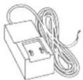
flowchart
graph TD
    A["Cloud"] --> B["Sensor"]
    B --> C["Sensor with antenna"]
    C --> D["Device with wireless signal"]
    D --> E["Server with network"]
    E --> F["Innenstation device with remote control"]

flowchart
graph TD
    A["User Interface"] --> B["Desktop"]
    B --> C["Cloud"]
    D["User Interface"] --> E["Desktop"]
    E --> F["Cloud"]
    G["Mobile Device"] --> H["Mobile Device"]
    I["User Interface"] --> J["User Interface"]
    K["User Interface"] --> L["User Interface"]
    M["User Interface"] --> N["User Interface"]
    O["User Interface"] --> P["User Interface"]
    Q["User Interface"] --> R["User Interface"]
    S["User Interface"] --> T["User Interface"]
    U["User Interface"] --> V["User Interface"]
    W["User Interface"] --> X["User Interface"]
    Y["User Interface"] --> Z["User Interface"]
flowchart
graph TD
    A["User Interaction"] --> B["Innenstationer 1"]
    C["User Interaction"] --> D["Innenstationer 2"]
    E["User Interaction"] --> F["Innenstationer 3"]
    G["User Interaction"] --> H["Innenstationer 4"]
    I["User Interaction"] --> J["Innenstationer 5"]
    K["User Interaction"] --> L["Innenstationer 6"]
    M["User Interaction"] --> N["Innenstationer 7"]
    O["User Interaction"] --> P["Innenstationer 8"]
    Q["User Interaction"] --> R["Innenstationer 9"]
    S["User Interaction"] --> T["Innenstationer 10"]
    U["User Interaction"] --> V["Innenstationer 11"]
    W["User Interaction"] --> X["Innenstationer 12"]
    Y["User Interaction"] --> Z["Innenstationer 13"]
    AA["User Interaction"] --> AB["Innenstationer 14"]
    AC["User Interaction"] --> AD["Innenstationer 15"]
    AE["User Interaction"] --> AF["Innenstationer 16"]
    AG["User Interaction"] --> AH["Innenstationer 17"]
    AI["User Interaction"] --> AJ["Innenstationer 18"]
    AK["User Interaction"] --> AL["Innenstationer 19"]
    AM["User Interaction"] --> AN["Innenstationer 20"]

Etagenruftaste

Innenstation
DoorBird IP Video
Türstation

Power over Ethernet (PoE) Switch
natural_image
Technical line drawing of a mechanical component with mounting holes and a central circular feature (no text or symbols)natural_image
Diagram of a smart home connection setup with devices and signal waves (no text or symbols)
natural_image
Diagram of a cable or wire connection inside a cylindrical device (no text or symbols)natural_image
Pure electrical circuit lines without any symbolsnatural_image
Abstract geometric pattern with orange and green diagonal stripes (no text or symbols)natural_image
Diagram showing a device with a central component and an adjacent server unit (no text or symbols visible)natural_image
Pure mechanical diagram showing two connected components with arrows indicating motion (no text or symbols)MANUEL D'INSTALLATION
natural_image
Isometric line drawing of a rectangular electronic device with a perforated base and top panel (no text or symbols)


natural_image
Pure architectural floor plan lines without any text, numbers, or symbolsnatural_image
Pure technical line drawing of a mechanical part outline (no text or symbols)
VIDÉOS
natural_image
Simple line drawing of a vertical panel with a small circular icon on the top-right corner (no text or symbols)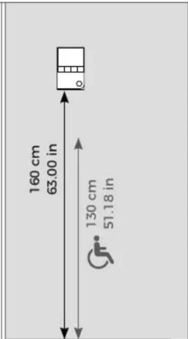
natural_image
Technical line drawing of a mechanical component with mounting holes and internal features (no text or symbols)natural_image
Diagram of a smart home with connected devices and signal icons (no text or symbols)i
natural_image
Diagram of a cable or wire connection inside a cylindrical device (no text or symbols)
natural_image
Pure electrical circuit lines without any symbolsnatural_image
Two abstract geometric pattern with diagonal orange and green stripes (no text or symbols) |

natural_image
Diagram showing a device with a central component and its side panel, no text or symbols present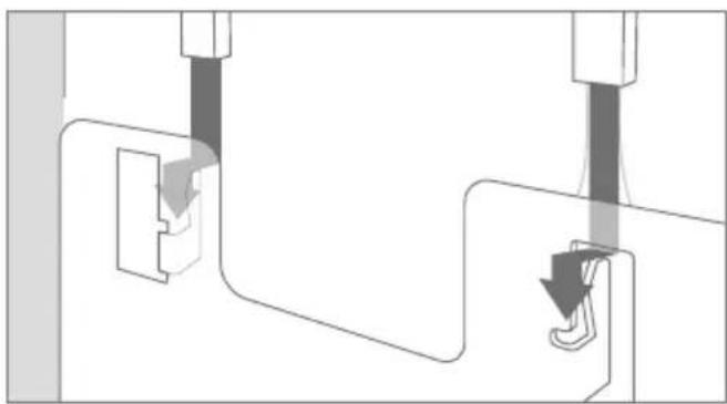
natural_image
Pure mechanical diagram showing a lever mechanism with no text or symbolsguide_a1101_fr.pdf
GUIDE DE
L'UTILISATEUR FINAL
natural_image
Line drawing of a rectangular electronic device with a grid and control panel (no text or symbols)

natural_image
Pure architectural floor plan lines without any text, numbers, or symbolsnatural_image
Pure technical line drawing of a mechanical part outline (no text or symbols)natural_image
Technical line drawing of a mechanical component with circular features and mounting holes (no text or symbols)natural_image
Diagram of a smart home with connected stairs and surveillance camera (no text or symbols)i
natural_image
Diagram of a cable or wire connection inside a cylindrical device (no text or symbols)natural_image
Pure electrical circuit lines without any symbolsnatural_image
Diagram of a device with a central component and an external panel, showing no text or symbols.natural_image
Pure mechanical diagram showing two connected components with arrows indicating motion direction (no text or symbols)STATEMENT OF CONFORMITY
Product Security and Telecommunications Infrastructure Act 2022
The Product Security and Telecommunications Infrastructure Regulations 2023
Manufacturer:
Hersteller:
IP Video Indoor Station
IP Video Innenstation
Type number:
Typnummer:
A1101
A1101
Intended purpose:
Verwendungszweck:
Indoor Station controlled via IP
2 Years starting August 2019
Support period extended to:
Report security issues to:
ResponsibleDisclosure @ doorbird.com
ResponsibleDisclosure @ doorbird.com
We, Bird Home Automation GmbH, declare under our sole responsibility that the above referenced product complies with the following:
The Product Security and Telecommunications
Infrastructure Regulations 2023 – Schedule 1
Conformity was assessed with the aid of the accessories/components that were included with delivery and described in the manual, including the current software officially approved for release. If other accessories/components are used, or current operating software not officially approved for release by Bird Home Automation GmbH, conformity with the above mentioned directives cannot be guaranteed.
This declaration is submitted by:
Berlin, April 17 ^th 2023
Berlin 17. April 2023
X. Maroudas
Xenios Maroudas
Director Product & Innovations
EU DECLARATION OF CONFORMITY (DoC)
IP Video Indoor Station
IP Video Innenstation
Type number:
Typnummer:
A1101
Intended purpose:
Verwendungszweck:
Indoor Station controlled via IP
We, Bird Home Automation GmbH, declare under our sole responsibility that the above referenced product complies with the following:
2014/53/EU Radio Equipment Directive (RED)
2022/30/EU Delegated Regulation supplementing
Directive 2014/53/EU (Cybersecurity, Data and Abuse Protection)
2011/65/EC RoHS 2 Directive
Health & Safety (Art. 3.1.a):
Cybersecurity requirements (Art. 3.3.d/e/f):
Cybersicherheitsanforderungen (Art. 3.3.d/e/f):
EN 18031-1:2024

The CE symbol confirms that this product conforms with the above mentioned norms and regulations.
Conformity was assessed with the aid of the accessories/components that were included with delivery and described in the manual, including the current software officially approved for release. If other accessories/components are used, or current operating software not officially approved for release by Bird Home Automation GmbH, conformity with the above mentioned directives cannot be guaranteed.
This declaration is submitted by:
Berlin, August 01st 2025
Berlin 01. August 2025

Sascha Keller
CEO