
D1100E - Video Intercom DoorBird - Free user manual and instructions
Find the device manual for free D1100E DoorBird in PDF.

| Product Type | IP Video Doorbell |
| Brand | DoorBird |
| Model | D1100E |
| Power Supply | 15 V DC power adapter (included), PoE IEEE 802.3af Mode A, or DIN rail power supply (optional) |
| Network Connection | Ethernet (Cat.5 cable or higher) or WiFi 2.4 GHz (depending on model) |
| Main Features | HDTV video, night vision, two-way audio, 4D motion sensor, Bluetooth, door relay, API, DoorBird Connect |
| Camera | Ultra wide-angle hemispherical lens, HDTV resolution |
| Audio | Integrated microphone and speaker |
| Motion Sensor | 4D technology, adjustable distance |
| Bluetooth | Bluetooth transceiver for optional remote control |
| Security | Banking-grade encryption, no port forwarding or DynDNS, automatic updates |
| Certifications | CE, FCC, IC, compliant with standards EN 60065, EN 60950, EN 62368 |
| Maintenance | Clean with soft cloth and soapy water, do not use abrasive products |
| Warranty | See www.doorbird.com/warranty |
Frequently Asked Questions - D1100E DoorBird
User questions about D1100E DoorBird
0 question about this device. Answer the ones you know or ask your own.
Ask a new question about this device
Download the instructions for your Video Intercom in PDF format for free! Find your manual D1100E - DoorBird and take your electronic device back in hand. On this page are published all the documents necessary for the use of your device. D1100E by DoorBird.
USER MANUAL D1100E DoorBird

DoorBird
Technology meets Design.

Page 2-19
Installation Manual
IP Video Door Station
D11x Series

Seite 20-37
Read these instructions carefully before starting to use any components. Keep the manual so you can refer to it at a later date if required. If you hand over the device to other persons for use, please hand over the operating manual as well.
You can always find the most up-to-date version of the installation manual on www.doorbird.com/support To make things easier we use the term "device" for the product "IP Video Door Station D11x series" and "mobile device" for a smartphone or tablet.
Liability
Every care has been taken in the preparation of this document. Please inform Bird Home Automation GmbH of any inaccuracies or omissions. Bird Home Automation GmbH cannot be held responsible for any technical or typographical errors and reserves the right to make changes to the product and manuals without prior notice. Bird Home Automation GmbH makes no warranty of any kind with regard to the content of this document, including, but not limited to, the implied warranties of merchantability and fitness for a particular purpose. Bird Home Automation GmbH shall neither be liable nor responsible for incidental or consequential damages in connection with the furnishing, performance or use of this material. This product is only to be used for its intended purpose.
Equipment Modifications
This equipment must be installed and used in strict accordance with the instructions given in the user documentation. This equipment contains no components that require service by the user. Unauthorized equipment changes or modifications will invalidate all applicable regulatory certifications and approvals.
Symbols used

Danger: Indicates a hazardous situation which, if not avoided, will result in death or serious injury.

Warning: Indicates a hazardous situation which, if not avoided, could result in death or serious injury.

Caution: Indicates a hazardous situation which, if not avoided, could result in minor or moderate injury.

Notice: Indicates a situation which, if not avoided, could result in damage to property.

Important: Indicates significant information which is essential for the product to function correctly.

Note: Indicates useful information which helps in getting the most out of the product.
Hazard information

WARNING
- Mounting, installation and servicing work on electrical devices may only be performed by a qualified electrician. Failure to observe this regulation could result in the risk of serious damage to health or fatal injury due to electric shocks.
- Devices with 110-240 V connection: The device may only be connected to an easily accessible power socket outlet. The mains adapter must be pulled out if a hazard occurs.
- For power supply, only use the original plug-in mains adapter delivered with the device, separately available DIN rail power supplies or a recommended PoE-Switch/PoE-Injector as specified in this manual.
- Because of electrostatic charging, direct contact with the circuit board can result in destruction of the device. Direct contact with the circuit board must therefore be avoided at any time.
- Observe the EN 60065 resp. EN 60950 resp. EN 62368 standard.
- Do not use the device if there are signs of damage to the housing, control elements or connecting sockets, for example, or if it demonstrates a malfunction. If you have any doubts, please have the device checked by an authorized expert.
- Do not open the device. This voids the warranty of the device. The device does not contain any parts that can be maintained by the user. In the event of an error, please have the device checked by an authorized expert.
- For safety, approval and licensing reasons (CE/FCC/IC etc.), unauthorized change and/or modification of the device is not permitted.
• The device is not a toy: do not allow babies and children to play with it.
• To avoid the danger of suffocation, keep any packing materials away from babies and children. Plastic films/bags, pieces of polystyrene, etc. are not a toy and can be dangerous in the hands of a child. Discard any packing materials immediately after removing the product. Do not reuse packing materials.
• Always lay cables in such a way that they do not become a risk to people and domestic animals.
• Voltage is applied to parts within the equipment. Do not touch any parts that are not associated with the installation, wiring, or connection. Electric shock could result. - On devices which are not marked as weatherproof: Keep the device away from water or any other liquid.
- Do not install or make any wire terminations while power supply is plugged in. It can cause electric shock or damage to the device.

WARNING
- Before turning on power, make sure wires are not crossed or shorted. If not, fire or electric shock could result.
- High voltage may be present internally. Do not open the device. Electric shock could result.
- The device is not of explosion-proof. Do not install or use near gases or flammable materials. Fire or explosion could result.
- Do not install two power supplies in parallel to a single input. Fire or damage to the device could result. Be sure to connect a single power supply to the device.
- Do not connect any terminal on the device to an AC power line. Fire or electric shock could result.
- Keep AC cord from being marred or crushed. If the AC cord is fractured, fire or electric shock could result.
- Do not plug or unplug with wet hands. Electric shock could result.
- Do not put any metal or flammable material into the device. Fire, electric shock, or device trouble could result.
- Existing wiring may contain high voltage AC electricity. Damage to the device or electric shock could result. Wiring and installation must be done by a qualified electrician.
- When mounting the device on a wall or ceiling, install the device in a convenient location, but not where it could be jarred or bumped. Injury could result.
- On devices with ground terminals, connect to an earth ground. Otherwise fire or malfunction could result.
- On devices with plastic or real glass, do not put high pressure on the glass. If fractured, injury could result.
- On devices with LCD, if LCD is punctured, do not allow contact with the liquid crystal inside. Injury could result. If necessary, gargle your mouth and clean your eyes or skin with clear water for at least 15 minutes and consult your doctor.
- Do not put anything on the device or cover the device with cloth, silicone, glue, coating, separate covering etc. Fire or device issues could result.
- Do not install the device in any of the following locations. Fire, electric shock, or device trouble could result.
- Places under direct sunlight or places near heating equipment that varies in temperature.
- Places subject to dust, oil, chemicals, hydrogen sulfide (hot spring).
- Places subject to moisture and humidity extremes, such as bathrooms, cellars, greenhouses, etc.
- Places where the temperature is very low, such
as inside a refrigerated area or in front of an air conditioner.
- Places subject to steam or smoke (e.g. near heating or cooking surfaces).
- Where noise generating devices such as dimmer switches or inverter electrical appliances are close by.
- Locations subject to frequent vibration or impact.
- On devices with intercom, be sure to perform a call test with low audio volume on both intercom devices. A sudden call etc. may arrive causing for example damage to your ear.
- If the device does not operate properly, unplug the power supply.
- All devices which are not marked as weatherproof are designed for indoor use only. Do not use outdoor.
- On devices which are marked weather-proof: Do not spray with high-pressure water. Device issues could result.
- We do not assume any liability for damage to property or personal injury caused by improper use or the failure to observe the hazard information. In such cases, any claim under warranty ceases. For consequential damages, we assume no liability!
- For devices that are supplied with a power supply unit: In accordance with Article 33 of the REACH Regulation (Regulation (EC) No. 1907/2006), we inform you that the metal contact of the plug pin of the mains adapter contains a concentration of >0.1% of the substance EC / List no.: 231-100-4 (lead) listed in the REACH Regulation. When used as intended, no measures are required to be able to use the product safely due to the lead concentration.
Safety instructions
NOTICE
- The device shall be used in compliance with local laws and regulations.
- Store the device in a dry and ventilated environment.
- Avoid exposing the device to shocks or heavy pressure.
- Do not install the device on unstable brackets, surfaces or walls. Make sure the material is strong enough to support the weight of the device.
- Use only applicable tools when installing the device. Using excessive force with tools could cause damage to the device.
- Do not use chemicals, caustic agents, or aerosol cleaners.
-
Use a clean dry cloth for cleaning.
-
Use only accessories that comply with technical specification of the device. These can be provided by Bird Home Automation GmbH.
- Use only spare parts provided by or recommended by Bird Home Automation GmbH.
- Do not attempt to repair the device by yourself. Contact Bird Home Automation GmbH for service matters.
- Keep the device more than 1 m (3.3') away from microwave, radio, TV, wireless router and any other wireless devices.
- On devices with intercom or built-in speaker or built-in microphone or signal transmission functions, keep the wires more than 30 cm (12") away from AC 100-240 V wiring. AC induced noise and/or device malfunction could result.
- Install the device in an area that will be accessible for future inspections, repairs and maintenance.
- If the device is used close to a cellular phone, the device may malfunction.
- The device can be damaged if dropped. Handle with care.
- The device turns inoperative during power failure.
- On devices with intercom or built-in speaker or built-in microphone, in areas where cellular or Radio / TV broadcasting station antennas are close by, the device may be affected by radio frequency interference.
- On devices with LCD screen, it must be noted in advance that the LCD panel, though manufactured with very high precision techniques, inevitably will have a very small portion of its picture elements always lit or not lit at all. This is not considered a device malfunction.
- On devices with intercom, due to the environmental sound around the device, it may hinder smooth communication, but this is not a malfunction.
- On devices with Username/Password, the Username/Password to access the device is the customer's responsibility. Make sure to use a password that cannot be easily guessed by a third party. We recommend that you change the Password on a regular basis.
• We will, under no circumstances, be liable for damage that occurs due to failures in power supply, network equipment or terminal devices; failures due to Internet providers and cellular network providers; failures such as disconnected lines and other losses in communication, which makes it impossible to provide this service as well as in any way delay this service due to any other causes outside of our responsibility; or if an error or missing data occurs during transmission.
FCC Caution:
Any Changes or modifications not expressly approved by the party responsible for compliance could void the user's authority to operate the equipment. This device complies with part 15 of the FCC Rules. Operation is subject to the following two conditions: (1) This device may not cause harmful interference, and (2) this device must accept any interference received, including interference that may cause undesired operation.
Note: This equipment has been tested and found to comply with the limits for a Class B digital device, pursuant to part 15 of the FCC Rules. These limits are designed to provide reasonable protection against harmful interference in a residential installation.
This equipment generates, uses and can radiate radio frequency energy and, if not installed and used in accordance with the instructions, may cause harmful interference to radio communications. However, there is no guarantee that interference will not occur in a particular installation. If this equipment does cause harmful interference to radio or television reception, which can be determined by turning the equipment off and on, the user is encouraged to try to correct the interference by one or more of the following measures:
- Reorient or relocate the receiving antenna.
- Increase the separation between the equipment and receiver.
- Connect the equipment into an outlet on a circuit different from that to which the receiver is connected.
- Consult the dealer or an experienced radio/TV technician for help.
This equipment complies with FCC radiation exposure limits set forth for an uncontrolled environment. This transmitter must not be co-located or operating in conjunction with any other antenna or transmitter.
IC Statement
EN: This device complies with Industry Canada license-exempt RSS standard(s). Operation is subject to the following two conditions:
(1) this device may not cause interference, and (2) this device must accept any interference, including interference that may cause undesired operation of the device.
This Class B digital apparatus complies with Canadian ICES-003.
IC radiation exposure: This equipment complies with ISEDC radiation exposure limits defined for a controlled environment. This transmitter must not be co-located or operated in conjunction with any other antenna or transmitter.
Information on disposal for users of waste electrical & electronic equipment (private household)
This symbol on the products and/or accompanying documents means that used electrical and electronic products should not be mixed with general household waste. For proper treatment, recovery and recycling, please take these products to designated collection points, where they will be accepted an a free of charge basis. Alternatively, in some countries you may be able to return your products to your local retailer upon the purchase of an equivalent new product. Disposing of this product correctly will help to save valuable resources and prevent any potential negative effects on human health and the environment which could otherwise arise from inappropriate waste handling. Please contact your local authority for further details of your nearest designated collection point. Penalties may be applicable for incorrect disposal of this waste, in accordance with national legislation.
Information on disposal in other countries outside the European Union
This symbol is only valid in the European Union. If you wish to discard this product, please contact your local authorities or dealer and ask for the correct method of disposal.
Transportation

When transporting the device, use the original packaging or equivalent to prevent damage to the device.
Warranty Information
For information about the device warranty, see www.doorbird.com/warranty
COMPONENTS\*
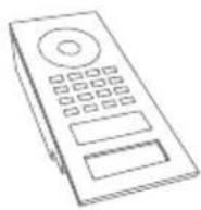
with call button(s) and front panel
natural_image
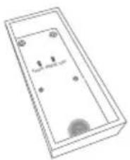
Simple line drawing of a rectangular box with internal components and a circular base (no text or symbols)1x Back-housing with wall-mounting bracket
1x Installation manual1x
Main Gluckitant Guide with Digital Passport

natural_image
Simple line drawing of a device with no text or symbols1x Drilling template 1x Waterproof A4 laser
printer paper for labelling
name plates
natural_image
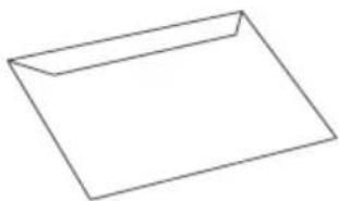
Simple line drawing of a rectangular envelope (no text or symbols)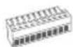
1x Screw connection terminal plug
natural_image
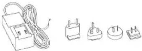
Illustration of four electrical components: a wire-wrapped box, two plug-in switches, and a terminal block (no text or symbols)1x Power supply unit (mains adapter) with up to four country-specific adapters
natural_image
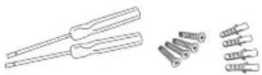
Line drawings of three different types of dental or mechanical tools (no text or symbols present)Small parts
* The sketches in this manual may differ from the purchased model.
DEVICE WITH 1 CALL BUTTON
Front Inside
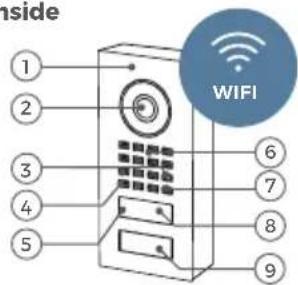
1) Front panel
2) HDTV Video
3) Security screws
4) Light Sensor
For night-vision mode
5) Bluetooth transceiver
6) Speaker
7) Microphone
8) 4D Motion sensor
9) Illuminated call button with nameplate
10) Diagnostic-LED Lights up a few seconds after connecting the device to power
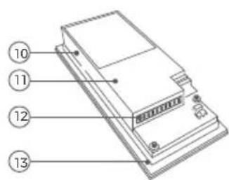
11) Main Electrical Unit
12) Screw connection terminal
13) Gasket
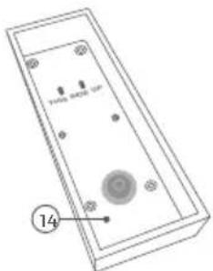
14) Housing with wall-mounting bracket
The flush-mounted model may differ optically.
DEVICE WITH 2 CALL BUTTONS
Front
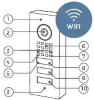
1) Front panel
2) HDTV Video
3) Security screws
4) Light Sensor For night-vision mode
5) Bluetooth transceiver
6) Speaker
7) Microphone
8) 4D Motion sensor
9) First illuminated call button with nameplate
10) Second illuminated call button with nameplate
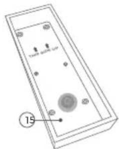
Inside

11) Diagnostic-LED Lights up a few seconds after connecting the device to power
12) Main Electrical Unit
13) Screw connection terminal
14) Gasket
15) Housing with wall-mounting bracket
The flush-mounted model may differ optically.
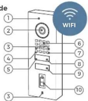
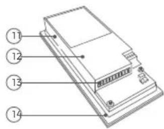
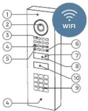
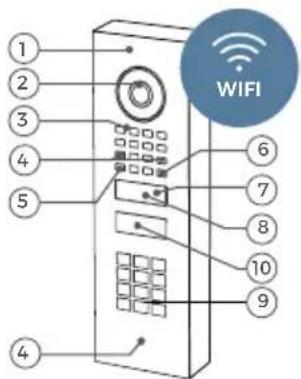
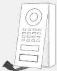
DEVICE WITH KEYPAD MODULE
Front
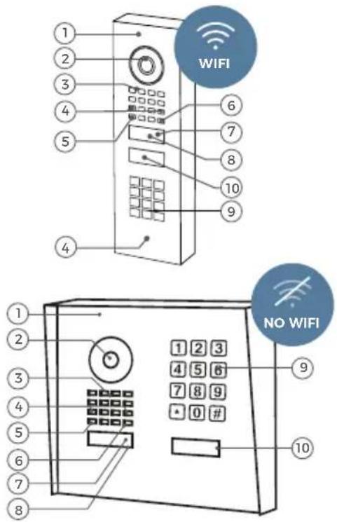
1) Front panel
2) HDTV Video
3) Speaker
4) Security screws
5) Light Sensor
For night-vision mode
6) Microphone
7) Bluetooth transceiver
8) 4D Motion sensor
9) Keypad Module The illumination is also acting as Diagnostic LED(s)
10) Illuminated modern call button (with nameplate) or illuminated classic call button (round)
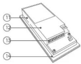
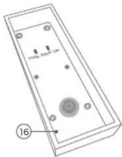
Inside
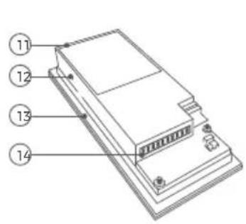

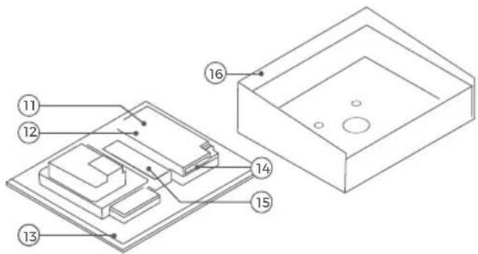
11) Main Electrical Unit
12) Diagnostic-LED Lights up a few seconds after connecting the device to power
13) Gasket
14) Screw connection terminal
15) Holder for 2-Wire Ethernet PoE Converter A1071 (optional)
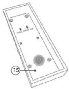
16) Housing with wall-mounting bracket
DEVICE WITH FINGERPRINT READER MODULE
Front Inside
1) Front panel
2) HDTV Video
3) Security screws
4) Light Sensor
For night-vision mode
5) Bluetooth transceiver
6) Speaker
7) Microphone
8) 4D Motion sensor
9) Illuminated call button with nameplate
10) Fingerprint Reader
11) Diagnostic-LED
Lights up a few seconds after connecting the device to power
12) Main Electrical Unit
13) Screw connection terminal
14) Gasket
15) Housing with wall-mounting bracket
The flush-mounted model may differ optically.
VIDEOS
Need help with the installation? Be sure to watch our installation videos which can be found on http://www.doorbird.com/support
Each individual step of the installation is clearly documented in the videos.
INSTALLATION
All the steps below should be carried out carefully by a competent adult, taking into consideration any applicable safety regulations. Please contact us directly or seek the advice of a competent specialist.

Please ensure that all wires used for the installation are undamaged along their entire length and approved for this type of use.
Network speed and network components
Please ensure that the upload speed of your Internet connection is at least 0.5 Mbps. The user experience is only as good as your network speed, network stability and quality of your network components, such as your Internet Router and WiFi access points or WiFi repeaters. Please also make sure that your network components are no older than two years old, have been manufactured by a well-known manufacturer, and have the latest firmware installed.
Should these requirements not be fulfilled, it may occur, for example that the performance of audio and video is poor or push notifications are delayed or do not arrive on your smartphone or tablet at all.
Requirements:
High-speed Internet (via landline): DSL, cable or optical fibre
Network: Ethernet, with DHCP
1
SWITCHING OFF POWER

Switch off the power to all wires leading to the assembly location, i.e. the door chime, electric door opener, power supply unit for the video door station etc.
2
DISMANTLING THE EXISTING DOORBELL
Should there already be a doorbell or door station on the exterior wall of the house, please remove it.
3
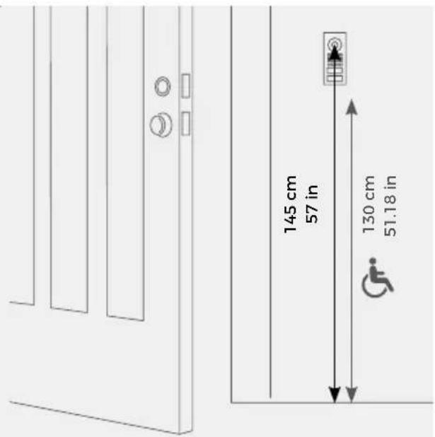
DETERMINING THE ASSEMBLY LOCATION
The device uses an ultra wide-angle hemispheric lens so that even when the person is a minimum distance of 50 cm (19.68 in) away from the device, a low installation height is sufficient. The lens is therefore not mechanically adjustable. The camera lens should be located at an altitude of at least 145 cm (57 in).
You may check this prior to the final mounting.
Only for D1101V & D1102V
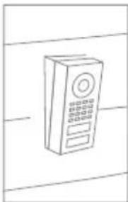
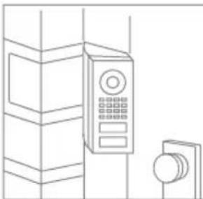
We offer additional wall-mounting kits for D1101V and D1102V Surface-Mount with a wedge corner wall-mount adapter (7.5° vertical down or up) and alternatively an angle corner wall-mount adapter (45° horizontal, mounts left or right).
natural_image
Line drawing of a mounted device with control panel (no text or symbols)A8001 Wedge corner wall-mount adapter (7.5°, mounts vertical down or up), sold separately

natural_image
Line drawing of a wall-mounted door with control panel and doorbell (no text or symbols)A8002 Angle corner wall-mount adapter (45° horizontal, mounts left or right), sold separately
When choosing the assembly location, consider the lighting conditions. Avoid direct sunlight, direct backlight and reflective surfaces.

Do not expose the device to direct sunlight. The housing temperature can exceed the maximum allowed temperature limit. This can result in damage of electric and mechanic components of the device and injuries especially when touching exterior parts of the device. White and bright silver-colored front plates absorb less sunlight than dark ones.

An image sensor must not be exposed to direct sunlight for an extended period of time. Direct sunlight will "blind" the camera and may permanently bleach the small color filters on the image sensor chip.

Any defects caused by direct sunlight are not covered by warranty.
Important note for cavity mounting (e.g. in pedestals and mailboxes):

To protect the electronic units, please ensure that the technical components are protected against dripping and running water caused by condensate or entering the mounting space through openings.
To protect the electronic units, ensure that the mounting space inside is not accumulating water.
Sufficient air circulation must be ensured, as well as unobstructed drainage of water at the base of the installation.
Failure to do so will result in warranty being declined.
4
ASSEMBLING THE MOUNTING HOUSING
The product is available as a surface-mounted and flush-mounted version. In the flush-mounted version, the front panel is slightly larger to better cover the hole in the wall, and the mounting housing (backbox) is made entirely of metal instead of plastic. If you use the flush-mounted housing, lever up the wall accordingly.
natural_image
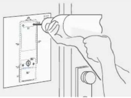
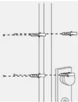
Pure electrical circuit lines without any symbolsIf the wall of the house is not made of wood, you should drill dowel holes 5 mm (0.19 in) in diameter in the wall according to the drilling template and then place the dowels provided into the boreholes.

If you must drill holes in a wall, insert screws into a wall or lever up a wall, ensure that no cables or mains (gas, water, etc.) are to be found in the wall.
If the wall of the house is made of wood, dowels are not normally required. There are special dowels for assembling the device on an insulating wall, e.g. Fischer insulating dowels.
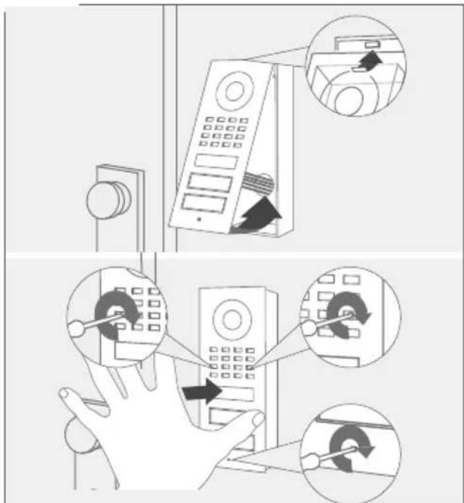
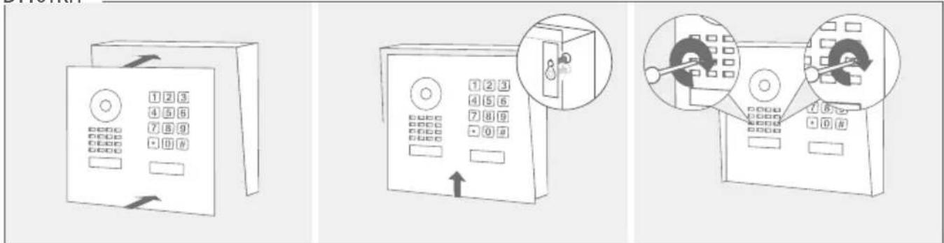
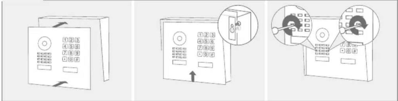
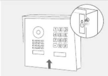
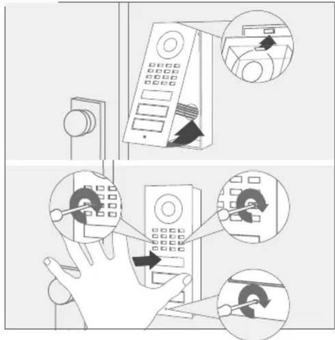
4.1 DISASSEMBLING THE FRONT PANEL
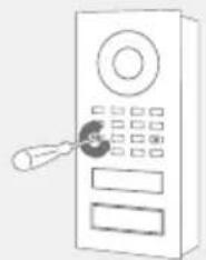
Remove the front panel with the attached Main Electrical Unit carefully from the mounting housing (backbox) using the orange (Torx+Pin) screw driver provided.

We have designed the front panel and safety screws in a way that they cannot be screwed through the front panel so that they do not fall off / get lost during installation.
D1101V
D1102V
D1101KH
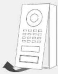
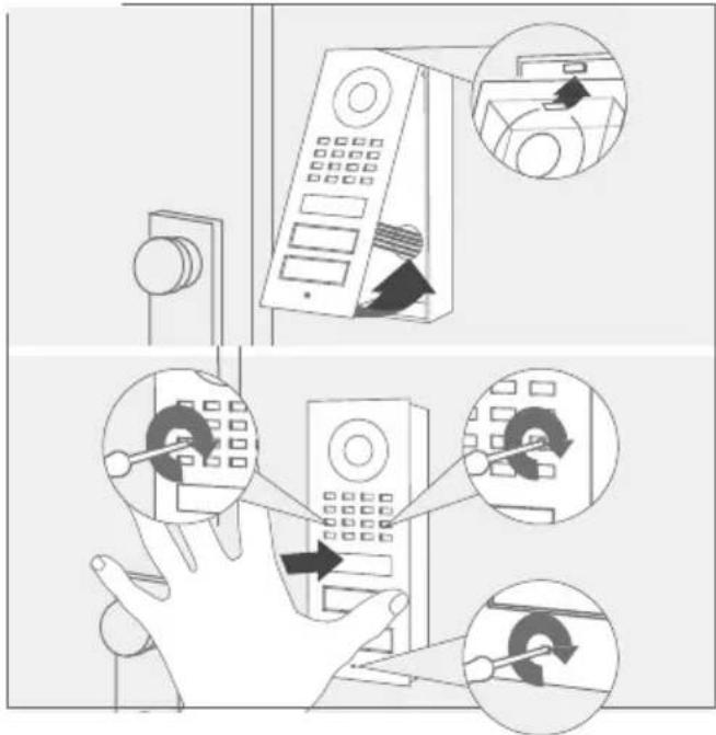
Turn the safety screws counter-clockwise until they are loose.
natural_image
Simple line drawing of a door with a key inserted, no text or symbols present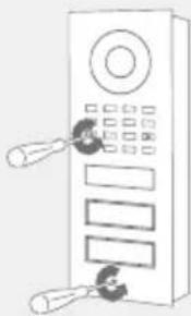
natural_image
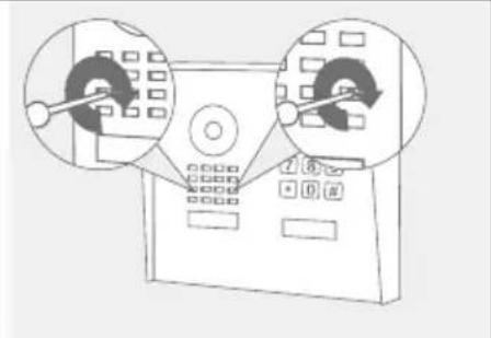
Line drawing of a control panel with buttons and display panels (no text or symbols)Turn the safety screws counter-clockwise until they are loose.
D1101V
D1102V
natural_image
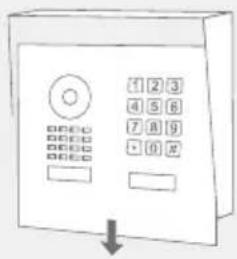
Line drawing of a rectangular electronic device with control panel and buttons (no text or symbols)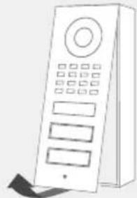
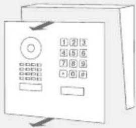
natural_image
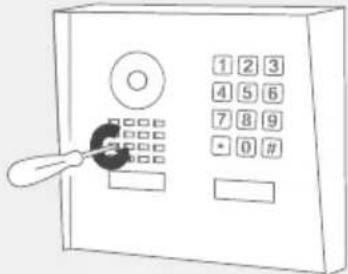
Line drawing of a remote control device with buttons and a scroll (no text or symbols)Pull the front panel with attached Main Electrical Unit out of the mounting housing (backbox).
D1101KH
Pull down the front panel.
Pull the front panel with attached Main Electrical Unit out of the mounting housing (backbox).
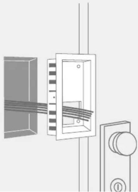
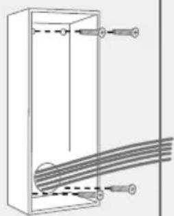
4.2 MOUNTING
Lead all cables and wires you want to connect to the device through the mounting housing. Screw the wall-mounting bracket of the mounting housing to the wall.
Flush-mounted models Surface-mounted models
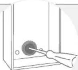
natural_image
Diagram of a mechanical or electrical component with internal wiring and a button (no text or symbols)Before mounting: Pierce through the middle of the rubber seal for the cable entry using a screwdriver.
natural_image
Simple line drawing of a hand holding a screwdriver inside a transparent container (no text or symbols)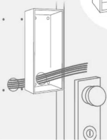
natural_image
Technical line drawing of a mechanical assembly with no visible text or symbols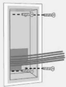
natural_image
Pure diagram of a rectangular device with internal components and no text or symbols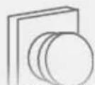
Please make sure that the outer frame of the flush-mounted housing rests on the outside of the wall and that the edge of the flush-mounted housing is sealed all around against moisture from the outside.
natural_image
Pure technical diagram of a rectangular structure with internal parallel lines and two connectors, no text or symbols present.
You can connect the device to the network by either using a WiFi 2.4 GHz connection (only for D1101V and D1102V) or a network cable.
OPTION 1
Network cable (recommended, maintenance free)
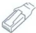
Install a network cable (which is plugged into a network switch / router with Internet access) from the inside of your building to the assembly location. The network cable between the assembly location and the network switch / router can have a maximum length of 80 m/262 ft (IEEE 802.3). If you must span a distance of more than 80 meters/262 feet you can put a network switch in between. Make sure to use a high-quality Cat.5 network cable or better and with proper shielding (Screened Foiled Twisted Pair (S/FTP or SFTP)) whereby the shield is connected to the outer metal shield of the RJ45 plug (8P8C).
The device itself does not have an RJ45 socket. The scope of delivery includes an RJ45 adapter that can be routed out of the housing. As an alternative, the RJ45 connector of the network cable can be removed on the device side to connect the wires directly to the Phoenix strip according to the assignment under point 7 „CONNECTING THE DEVICE“.

OPTION 2
WiFi 2.4 GHz (only for D1101V and D1102V)
When using WiFi please make sure you have a good WiFi signal at the assembly location of the device. You can increase the WiFi signal by using so called "WiFi repeaters", which can boost your WiFi signal. You should install such a WiFi repeater close to the assembly location of the device, typically inside your home and close to the device.
For further information regarding WiFi installations, please visit www.doorbird.com/wifi
6
PREPARE POWER SUPPLY
The device does not have a battery as power supply, therefore, choose one of the following options.
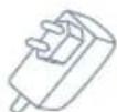
OPTION 1
Power supply using the power supply unit (mains adapter)
To power the device using the provided mains adapter, 2 insulated wires are required. The power supply unit has a 300 cm (9.8 ft) long cable with two insulated wires. The network connection is then established via a network cable or alternatively via WiFi.

Do not plug the power supply unit into the wall socket yet.
Only use the power supply unit provided along with the device, or a DIN-rail power supply unit (see "OPTION 3") that you can obtain from us separately, since this has been specially stabilized electrically and is equipped with an integrated audio interference reduction device. Other power supply units may destroy the

If you have only two wires available at the assembly location, you may use the "DoorBird 2-Wire Ethernet PoE Converter A1071", sold separately. It allows you to transfer network data (Ethernet) and power (PoE) with a simple two-wire cable over long distances. For example, existing buildings with a simple two-wire bell wire can be equipped with network technology without having to retrofit any network cables.
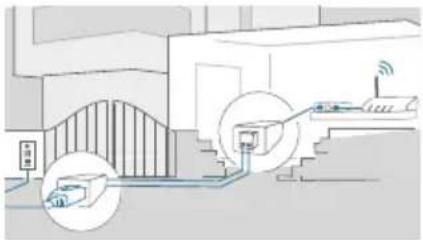
natural_image
Interior view of a modern building with curved roof and adjacent staircase, showing two circular insets of devices (no text or symbols visible)
For reasons of network stability, we principally recommend using a network cable, as WiFi is sensitive to interference (range, house walls acting as shields, reliability of performance, third party WiFi networks, wireless transmitters causing interference in the area, etc.).

The provided mains adapter is only capable to power one device. It is not designed to power multiple devices simultaneously.
If you must power more than one device with one power supply, we recommend to use a PoE-Switch with PoE Standard IEEE 802.3af Mode A or an appropriate DIN rail power supply (see "OPTION 3").
device or cause poor transmission quality. The warranty automatically expires if you use a different power supply unit.

The power supply unit is plugged into a wall socket inside your house, usually where the two wires from your assembly location come out of the wall in the interior of the house.

The provided mains adapter is not outdoor-ready and for indoor-use only.
OPTION 2
Power supply and network connection using PoE (Power over Ethernet)
To power the device via a PoE-Switch (e.g. D-Link DGS-1008P) or PoE-Injector (e.g. DoorBird Gigabit PoE Injector A1091), use a CAT.5 cable or higher in accordance with the PoE standard IEEE 802.3af Mode A.
A CAT.5 cable or higher must be used for this purpose, as network signals can only be transmitted over completely insulated, shielded and twisted cables. If you use PoE as a source of power, the four wires for PoE then simultaneously form the data line. The device will not start if your PoE-Switch/PoE-Injector does not support the PoE Standard IEEE 802.3af Mode A.

Do not combine the power supply from the power supply unit (mains adapter) with the power supply via PoE.
You can find further information about PoE here: http://www.doorbird.com/poe

- Disconnect the PoE-Switch or PoE-Injector from the power grid.
- Place the network cable in the installation site of the device.
OPTION 3
Power supply using a DIN rail power supply unit
Alternatively to the mains adapter, we offer DIN rail power supplies in our online shop, which can be installed by a specialist. The network connection is then made via a network cable or alternatively via WiFi.
7
CONNECTING THE DEVICE
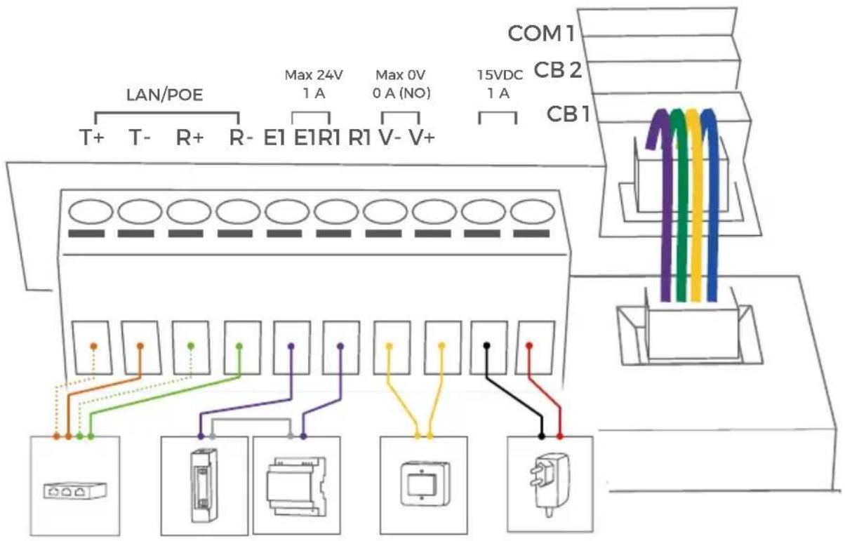
It is possible to connect the cables and wires to the device conveniently and safely via the labeled screw connection terminal. You can connect all necessary cables and wires to the device now.

Please remove any cables and wires from the connection ports of the device that you do not need.

If you must power more than one device with one power supply, we recommend to use a PoE-Switch with PoE Standard IEEE 802.3af Mode A or an appropriate DIN rail power supply (see "OPTION 3").

Theoretically (not recommended by us!), an unshielded, but over the whole length (max. 80 m/262 ft) twisted bell wire with two pairs of wires (first twisted pair of wires: "T+, T-", second twisted pair of wires "R+, R-") can be used for the network and PoE transmission as an alternative to a Cat.5 network cable or better. This is comparable to a Cat.3 network cable. In this case, however, we cannot guarantee the data throughput or the stability of the network connection and power supply; this must be measured and checked on site by qualified personnel over several hours (network data is transmitted at high frequency, therefore a shielded Cat.5 network cable twisted in pairs or better must normally be used).

For easier installation we strongly recommend to remove the plug from screw connection terminal while you connect the cables and wires.
Port Description
LAN/POE The device does not have an integrated standardized RJ45 socket to ensure ...
- that the device rests as flat as possible on the wall.
- that no wall needs to be levered up.
- that a strong and inflexible Cat.6 or Cat.7 installation cable can be used.
Use only four wires (1, 2, 3 and 6) of a standard Network cable Cat.5 or better, coming from the Internet Router/PoE-Switch/PoE-Injector.

Cat.5 / Cat.6 Network cable
T+ White and orange network cable wire (Number 1, Transmit Data +)
T - Orange network cable wire (Number 2, Transmit Data -)
R+ White and green network cable wire (Number 3, Receive Data +)
R - Green network cable wire (Number 6, Receive Data -)
Cat.7 Network cable (Installation cable)

T+ White network cable wire from pair "orange/white" (Number 1, Transmit Data +)
T- Orange network cable wire from pair "orange/white" (Number 2, Transmit Data -)
R+ White network cable wire from pair "green/white" (Number 3, Receive Data +)
R- Green network cable wire from pair "green/white" (Number 6, Receive Data -)

Do not power the device simultaneously via the power supply from the power supply unit (mains adapter) and the power supply via PoE.
| R1, R1 Bi-stable latching relay #1, max. 24 V DC/AC, 1 A. Security feature: The relay keeps its state even in the case of loss of power. You can configure the default state of the relay (open/close) via the DoorBird App. These ports can be used to connect e.g. an electric door opener. The device does not supply power to the connected device. The power supply for the electric door opener must be installed separately. | |
| When wiring an electric door opener directly to a door station, there is a risk that the electric door opener could be tampered by unauthorized third parties (e. g. by breaking the door station and short-circuiting the wiring of the door opener). Therefore, we generally recommend the use of a remote safety relay mounted indoors (e. g. DoorBird I/O Door Controller A1081) for wiring an electric door opener for a more secure installation in your home. | |
| E1, E1 Digital Input (0 V, 0 A (NO)), for door opener button, max. 0 V DC/AC, 0 A. These ports can be used to connect e.g. a door opener button inside the home. It will can trigger the bi-stable latching relay of the device (R1, R1)NOTICE Please make sure to add no voltage on these ports. Extra voltage may destroy the device immediately. | |
| 15 VDC - 15 V DC Power supply input, negative pole (-). Please connect the black wire of the power supply unit (mains adapter) supplied with this device if you do not power the device using PoE. We only recommend PoE. | |
| Do not power the device simultaneously via the power supply from the power supply unit (mains adapter) and the power supply via PoE. | |
| 15 VDC + 15 V DC Power supply input, positive pole (+). Please connect the red wire of the power supply unit (mains adapter) supplied with the device here, if you do not power the device using PoE. We only recommend PoE. | |
| Do not power the device simultaneously via the power supply from the power supply unit (mains adapter) and the power supply via PoE. | |
| COM 1 Jack for authorized peripherals of Bird Home Automation which will be released in the future, e.g. keypad | |
| CB 2 Jack for second call button. | |
| CB 1 Jack for first call button. | |
The jacks "CB1", "CB2" and "COM1" on the rear side of the Main Electrical Unit must only be used to connect components certified by Bird Home Automation.
| CALL BUTTON PORT — | |
| SWITCH(4 PIN) | Use the four wire call-button cable provided to connect the call-button to the Main Electrical Unit (already connected in delivery condition to the jack "CB1"/"CB2"). |
NOTICE Please take care when connecting the cables and wires. Connecting the cables and wires the wrong way may damage the device. Wires without insolation material must not protrude out of the green screw connection terminal, it may lead to electrical short and damage the device.
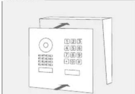
Assemble the front panel with the attached Main Eletrical Unit carefully using the orange (Torx+Pin) screw driver provided.
D1101V D1102V

D1101KH
While turning the screws clockwise, press the front panel firmly onto the housing until the screws are tightened.

Tighten the safety screws by hand only (less than 5 newton meter [Nm]), otherwise the Main Eletrical Unit housing may be damaged.
9
ACTIVATE THE DEVICE
If the device is to be supplied with power by a mains adapter, plug the power adapter of the device into a wall socket. If the device is to be powered via PoE, switch on the PoE-Switch/PoE-Injector which is connected to the device. If the device is to be powered via DIN-rail power supply, switch on the DIN-rail power supply.
The Diagnostic-LED indicates whether the device is supplied with power. This LED lights up in green color a few seconds after you have connected the device to the power supply.
If the Diagnostic LED does not light up, please check the power supply. When using a wall-plug power supply and not PoE please check whether you have connected the positive pole and negative pole to the device correctly.
The device is ready for operation (booting up process, any software updates, etc.) once it has emitted a short diagnosis sound from the integrated loudspeaker. This may last for up to 5 minutes.
10
DOWNLOADING AND INSTALLING THE APP
Download the "DoorBird" App by Bird Home Automation onto your mobile device from the Apple App
Store or Google Play Store. You can always find the most up-to-date version of the App manual on www.doorbird.com/support.
If you use WiFi for connecting the device to your Internet Router, first go to the DoorBird App > "WiFi Setup" and follow the instructions.
If you have finished the WiFi setup or have connected the device to your Internet Router by means of a network cable, go to the DoorBird App > "Add device" and click on the QR code icon in the "User" field.
Scan the user QR code found on the "Digital Passport" provided with the device.
If you have problems adding the device to the App please check if the device is online ( www.doorbird.com/ checkonline ). If the device is not online, please check the WiFi or network cable connection again.
DIAGNOSTIC-LED
You can see if the device is powered by checking the Diagnostic LEDs, which lights up a few seconds after the power is connected.
The Diagnostic-LED is designed to illuminate only slightly.
DIAGNOSTIC-SOUNDS
After around one minute, the device emits brief diagnostic sounds after it has been connected to power supply / network / internet.
LENS
The product uses a straightened Wide-Eye hemispheric lens (HD). Due to the wide angle of coverage (horizontal, vertical, diagonal), a small edge may appear in the corners of the image as well as reflections in the image from the surface of the front of the unit.
MOTION SENSOR
The device has a built-in Motion Sensor with 4D Technology. You can use it for numerous applications, e.g. to send an alarm to a mobile device or to switch a relay to turn on an outdoor light.
The adjustable distance is optimized for a 1.75m (69 in) tall 70kg (165 lbs) person in a free environment. The accuracy of the distance of the motion sensor can vary depending on the environment.
BLUETOOTH TRANSCEIVER
The device has a built-in Bluetooth® transceiver. Compatible with the DoorBird Bluetooth Keyfob Remote A8007.
API
The device features a well documented API for third-party integration. For information, terms and conditions see www.doorbird.com/api
DOORBIRD CONNECT
The device features many options to integrate it into third-party applications. For information, terms and conditions see www.doorbird.com/connect
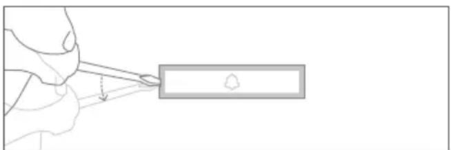
CHANGING THE LABEL OF A CALL BUTTON NAMEPLATE
Applies only to devices with 1 and more illuminated call buttons with nameplate.
natural_image
Illustration of a hand using a tool to mark a small object on a rectangular object (no text or symbols present)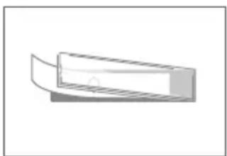
natural_image
Simple 3D illustration of a rectangular object with a curved edge, resembling a stylized document or container (no text or symbols)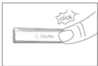
MAINTENANCE OF THE FRONT PANEL
Cleaning and maintenance instructions
All of our front panels are made of high-quality materials and are designed for a durable lifetime. Since door stations are usually installed in unprotected outdoor areas, they are exposed to adverse weather conditions and aggressive substances, especially close to frequently used roads, in coastal and industrial areas. Therefore, please consider the following care instructions. Unfortunately, we cannot accept any liability for damage if these instructions are not being observed. Aggressive dirt such as bird droppings should be removed as quickly as possible.

Aggressive stains such as bird droppings should be removed as soon as possible.

Never use abrasive detergents such as steel wool or scouring milk!
Warm water is usually sufficient, if necessary with a little detergent, a soft cloth or brush. Plastic parts (camera or name tags) must not be treated with metal care products. Remove all residues of cleaning agents or lubricants to avoid stains or discolouration after the maintenance.
Stainless Steel
Only high-quality stainless steel is used for all available DoorBird door stations. However, high-quality stainless steel can also rust, as approx. 70% of stainless steel is made of iron. Rust resistance is only achieved by a protective layer (also called passive layer), which covers the iron like a skin. This protective layer consists essentially of chromium and other precious metals.
Iron particles, grinding dust and chips deposited on stainless steel can lead to corrosion (rust film). These iron particles can be found everywhere, but especially in coastal and industrial areas and close to frequently used roads. Please remove ferrous deposits immediately, as they will attack your door station and lead to real rust if not removed. To remove rust, simply wipe off the dust; in addition, a care product is recommended, e.g. WD 40, available e.g. at Amazon for less than € 5.00. Simply apply in a thin layer and rub in. The same applies if rust appears on the engravings on the stainless steel surface.
Cement or lime splashes should be carefully removed as soon as possible with a wooden spatula before hardening.
The following cleaning detergents are not to be used as they reduce corrosion resistance:
- products containing chloride and hydrochloric acid
- Bleach (in case of accidental use, rinse thoroughly with water)
• Silver polish
After the cleaning with clear water wipe with damp
cloth and rub dry to avoid lime traces. Lime residues can be avoided by using demineralised water.
Stainless steel PVD coated
PVD coated, chrome-plated or gold-plated surfaces are recommended to be cleaned with a grease-dissolving detergent and clear water or with a clean and dust-free microfibre cloth. For high-gloss surfaces, use a scratch-free cloth (e.g. cleaning cloth for glasses, furniture polishing cloth, etc.).
Lacquered surfaces
Clean painted surfaces and lettering with a soft, scratch-free cloth moistened with a mild soap solution (e.g. cleaning cloth for glasses, furniture polishing cloth, etc.). To prevent stains or discolouration, the detergents should be wiped off without leaving any residue. Be particularly careful with lettering in order not to damage the film or the print.

TROUBLESHOOTING
The device does not power up
If the device is to be supplied with power by a mains adapter, plug the power adapter of the device into a wall socket. If the power adapter was already plugged into a wall socket, check if the cables and wires are correctly connected to the screw connection terminal. In most cases, removing the cable and wires from the screw connection terminal plug and reconnecting them to the screw connection terminal plug helps (loose contact). If you are powering more than one device simultaneously with one mains adapter, check if the mains adapter is able to deliver enough power over the full cable length.
If the device is to be powered via PoE, switch on the PoE-Switch/ PoE-Injector which is connected to the device. If the PoE-Switch/ PoE-Injector was already switched on, check if the cables and wires are correctly connected screw connection terminal. In most cases, removing the cable and wires from the screw connection terminal plug and reconnecting them to the screw connection terminal plug helps (loose contact). If the problem still exists, please check if your PoE-Switch / PoE Injector supports the PoE Standard IEEE 802.3af Mode A, see also www.doorbird.com/poe
If the device is to be supplied with power by a DIN-rail power supply, switch on the DIN-rail power supply. If the DIN-rail power supply was already switched on, check if the cables and wires are correctly connected to the screw connection terminal. In most cases, removing the cable and wires from the screw connection terminal plug and reconnecting them to the screw connection terminal plug helps (loose contact). If you are powering more than one device simultaneously with one DIN-rail power supply, check if the DIN-rail power supply is able to deliver enough power over the full cable length.
The device does not connect to network via network cable ("No Network" diagnosis sound)
In most cases, removing the cable and wires from the screw connection terminal plug and reconnecting them to the screw connection terminal plug helps (loose contact). If the problem still exists, please check if the network cable is properly connected to your router / switch and the network cable is not broken.
If the problem still exists, please check if your Router has DHCP turned on and is able to assign an IP address to the device.
The device does not connect to Internet ("No Internet" diagnosis sound)
In most cases, your Internet is down or your router blocks Internet access for the device. Please see www.doorbird.com/downloads/ports.pdf
If the problem still exists, please check if your Router has DHCP turned on and is able to assign an IP address to the device.
The device does not connect to Internet
In most cases, your Internet is down or your router blocks Internet access for the device. Please see www.doorbird.com/downloads/ports.pdf
LEGAL NOTES
General remarks
- DoorBird is a registered trademark of Bird Home Automation GmbH.
- Apple, the Apple logo, Mac, Mac OS, Macintosh, iPad, Multi-Touch, iOS, iPhone and iPod touch are trademarks of Apple Inc.
- Google, Android and Google Play are trademarks of Google, Inc.
- The Bluetooth® word mark and logos are registered trademarks of Bluetooth SIC, Inc.
- QR Code is a registered trademark of Denso Wave Incorporated in Japan and other countries.
- All other company and product names may be trademarks of the respective companies with which they are associated.
- We reserve the right to make changes to our products in the interests of technical advancement. The products shown may also look different from the products supplied based on ongoing enhancement.
- Reproducing or using texts, illustrations and photos from this instruction manual in any media - even if only in the form of excerpts - shall only be permitted with our express written consent.
- The design of this manual is subject to copyright protection. We do not accept any liability for any errors or any erroneous content or printing errors (even in the case of technical specifications or within graphics and technical sketches).
- Our products are in compliance with all technical guidelines, electrical and telecommunications regulations applicable in Germany, the EU and the USA.
- Our products and also the components contained therein (ICs, software, etc.) may only be used for civilian non-military purposes.
Data privacy and data security
- For maximum security, the device uses the same encryption technologies as are used in online banking. For your security, no port forwarding or DynDNS is used either.
- The data centre location for remote access over the Internet by means of an App is obligatory in the EU if the determined Internet IP-Address location of the device is within the EU. The data centre is operated in line with the most stringent security standards.
- Video, audio and any other surveillance methods can be regulated by laws that vary from country to country. Check the laws in your local region before installing and using this device for surveillance purposes.
If the device is a door-, indoor station or camera:
- In many countries video and voice signal may only be transmitted once a visitor has rung the bell (data privacy, configurable in the App).
- Please carry out the mounting in such a way that the detection range of the camera limits the device exclusively to the immediate entrance area.
- The device may come with a visitor history and motion sensor. You can activate/deactivate this function if required.
If necessary, indicate the presence of the device in a suitable place and in a suitable form.
Please observe any relevant country-specific statutory regulations concerning the use of surveillance components and surveillance cameras applicable at the installation site.
Check with the property owner and your house community if you are allowed to install and use this product. Bird Home Automation GmbH cannot be held responsible for any miss-use or miss-configuration of this product, including the unauthorized opening of a door.
Bird Home Automation cannot be held responsible for damages caused by improper existing installations or improper installation.
Software and operating system's updates (so-called "firmware updates") are generally automatically installed on the products of Bird Home Automation GmbH via Internet, if technically possible. Automatic firmware updates keep the products' software up to date so that they always work reliably, safely and efficiently. Through further development, features can be added, extended or slightly changed. Major changes or limitations to existing features will generally occur if Bird Home Automation GmbH deems it necessary (e.g. for data protection, data security or stability reasons, or to keep them up to date). When a firmware update is available, Bird Home Automation GmbH's servers generally automatically distribute it to all compatible products connected to the Internet or Bird Home Automation GmbH's servers. This process is gradual and can take several weeks. As soon as a product receives a firmware update, the system will be installed and will restart by itself. Installed firmware updates cannot be undone. Since the products and software of Bird Home Automation GmbH are not explicitly customer-specific products, a customer cannot deny an automatic update if the product is connected to the Internet or to the Bird Home Automation GmbH's server.
Publisher
It is possible that these manual still contains typographical errors or printing errors. The information in this manual will be checked regularly and corrections will be made in the next version. We accept no liability for errors of a technical or printing nature and their consequences.
natural_image
Simple line drawing of a rectangular device with internal components and a circular base (no text or symbols)natural_image
Simple line drawing of a device with no text or symbols1x Bohrschablone
natural_image
Simple line drawing of a rectangular envelope (no text or symbols)
10) Diagnose LED
1) Frontblende
2) HDTV Video
3) Lautsprecher
4) Sicherheitsschrauben
5) Lichtsensor
natural_image
Line drawing of a door with a mounted phone and lock, no text or symbols presentnatural_image
Line drawing of a wall-mounted phone unit and a doorbell (no text or symbols)natural_image
Line drawing of a door with control panel and handle (no text or symbols)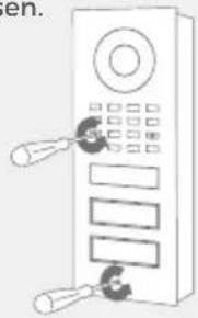
natural_image
Illustration of a control panel with buttons and display panels (no text or symbols)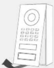
natural_image
Line drawing of a remote control device with buttons and a keypad (no text or symbols)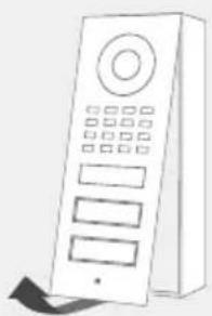
natural_image
Line drawing of a remote control device with buttons and a scroll (no text or symbols)
natural_image
Technical line drawing of a mechanical assembly with a rectangular housing and a vertical rod (no text or symbols)natural_image
Simple line drawing of a tool inserted into a circular component inside a rectangular frame (no text or symbols)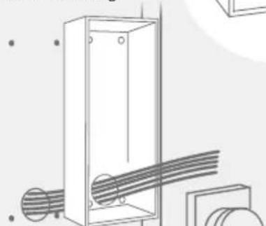
natural_image
Illustration of a cabinet with coiled cables and electrical components (no text or symbols)natural_image
Pure diagram of a rectangular device with internal components and no text or symbols
natural_image
Pure technical diagram of a rectangular enclosure with internal layered structure and no text or symbols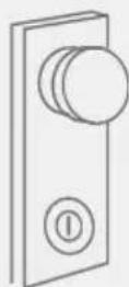
5
natural_image
Diagram showing a gate, sensor, and Wi-Fi unit in an indoor setting (no text or symbols)
natural_image
Two abstract geometric pattern with diagonal stripes in orange and green (no text or symbols)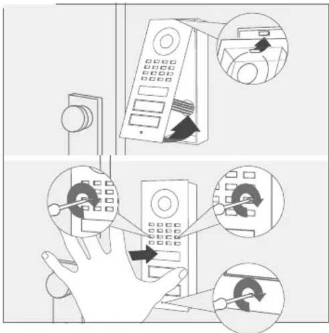

natural_image
Illustration of a hand holding a tool with a small bell icon, no text or symbols present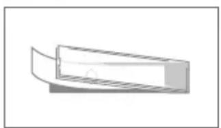
natural_image
Simple line drawing of a rectangular object with a curved edge, no text or symbols present.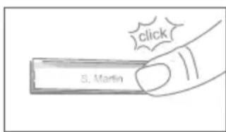
MANUEL D'INSTALLATION
natural_image
Simple line drawing of a rectangular enclosure with internal compartments and a circular base (no text or symbols)natural_image
Simple line drawing of a device with a rectangular frame and control buttons (no text or symbols)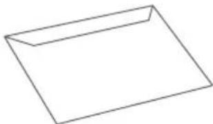
natural_image
Simple line drawing of a rectangular envelope (no text or symbols)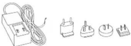
natural_image
Illustration of four electrical components: a wire-wrapped box, three connected plug-in blocks, and two separate plug-in blocks (no text or symbols)natural_image
Illustration of four different types of dental implants or tools, including a tool with handles and multiple screws arranged in groups (no text or labels)1x Adaptateur RJ45
à vis


Conditions requises:
natural_image
Line drawing of a wall-mounted device with control panel and door (no text or symbols)natural_image
Line drawing of a wall-mounted control panel with circular buttons and a separate monitor (no text or symbols)Sufficient air circulation must be ensured, as well as unobstructed drainage of water at the base of the installation.
Failure to do so will result in warranty being declined.
4
ASSEMBLAGE DU BOÎTIER DE MONTAGE
natural_image
Pure mechanical diagram showing alignment of springs and rollers with dashed alignment lines (no text or symbols)natural_image
Line drawing of a control panel with a knob and indicator lights (no text or symbols)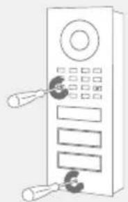
natural_image
Line drawing of a control panel with buttons and display panels (no text or symbols)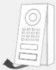
natural_image
Illustration of a mobile phone with control panel and buttons (no text or symbols)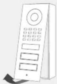
natural_image
Line drawing of a remote control device with buttons and a scroll (no text or symbols)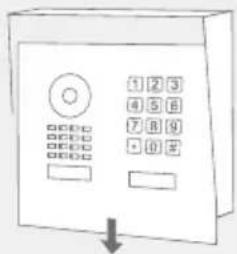
natural_image
Technical line drawing of two electrical wall-mounted components with wiring and mounting holes (no text or symbols)natural_image
Architectural diagram showing a building with stairs and a staircase, featuring circular annotations of a vehicle and signal waves (no text or symbols present)
D1101KH
ns
e

natural_image
Line drawing of a hand using a tool to mark a button or connector (no text or symbols present)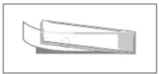
natural_image
Simple 3D diagram of a rectangular object with a curved edge, no text or symbols present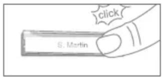
ENTRETIEN DE LA FACE AVANT
natural_image
Simple line drawing of a rectangular box with internal components and a circular base (no text or symbols)natural_image
Blank rectangular document with faint lines and a small label on top (no readable text or symbols)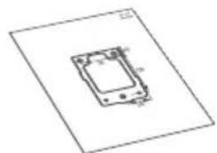
natural_image
Simple line drawing of a square electronic component with mounting holes (no text or symbols)
natural_image
Simple line drawing of a rectangular envelope (no text or symbols)natural_image
Illustration of four different types of dental tools or implants: a tool with flat blade, a series of screws, a multi-pronged screw, and a triangular base (no text or symbols present)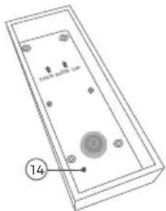

natural_image
Line drawing of a wall-mounted device with a control panel and two buttons, no text or symbols present.natural_image
Line drawing of a wall-mounted control panel and a circular button (no text or symbols)natural_image
Line drawing of a hand using a tool to adjust or install a wall-mounted device (no text or symbols visible)natural_image
Pure electrical circuit lines without any symbolsnatural_image
Two identical line drawings of a control panel with buttons and display screens, no text or symbols present.D1101KH
D1101V
D1102V
natural_image
Line drawing of a remote control device with keypad and buttons (no text or symbols)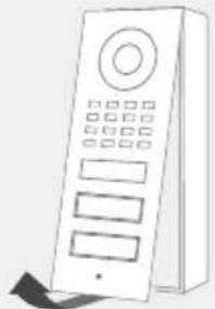
natural_image
Line drawing of a remote control device with buttons and a scroll (no text or symbols)natural_image
Pure technical diagram of a mechanical assembly with no visible text, numbers, or symbolsnatural_image
Simple line drawing of a hand inserting a screw into a container (no text or symbols)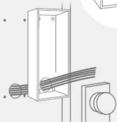
natural_image
Technical line drawing of a mechanical assembly with coiled wires and mounting brackets (no text or symbols)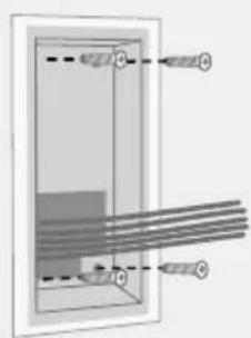
natural_image
Pure diagram of a rectangular device with internal parallel lines and labeled ports (no text or symbols)natural_image
Pure technical diagram of a rectangular box with internal curved lines and two protruding elements (no text or symbols)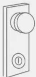
natural_image
Diagram showing two connected devices with sensors and a bridge, no text or symbols present
D1101KH

NOTICE
TRANSCEPTOR BLUETOOTH
natural_image
Line drawing of a hand holding a rectangular object with a small triangular symbol inside, no text or labels present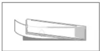
natural_image
Simple 3D illustration of a curved rectangular object with a shaded base (no text or symbols)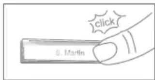
MANTENIMIENTO DE LA PLACA FRONTAL
STATEMENT OF CONFORMITY
Product Security and Telecommunications Infrastructure Act 2022
The Product Security and Telecommunications Infrastructure Regulations 2023
| Manufacturer:Hersteller: | Bird Home Automation GmbHUhlandstr. 16510719 BerlinGermany |
| Brand:Marke: | DoorBirdDoorBird |
| Product:Produkt: | IP Video Door StationIP Video Türstation |
| Type number:Typnummer: | D11x product seriesD11x Prosuktserie |
| Intended purpose:Verwendungszweck: | IP Video Door StationIP Video Türstation |
| Support period:Supportzeitraum: | 2 Years starting October 20232 Jahre beginnend Oktober 2023 |
| Support period extended to:Supportzeitraum erweitert bis: | June 2025Juni 2025 |
| Report security issues to:Melden Sie Sicherheitsprobleme an: | ResponsibleDisclosure @ dooResponsibleDisclosure @ doorbird.com |
We, Bird Home Automation GmbH, declare under our sole responsibility that the above referenced product complies with the following:
The Product Security and Telecommunications
Infrastructure Regulations 2023 – Schedule 1
Conformity was assessed with the aid of the accessories/components that were included with delivery and described in the manual, including the current software officially approved for release. If other accessories/components are used, or current operating software not officially approved for release by Bird Home Automation GmbH, conformity with the above mentioned directives cannot be guaranteed.
This declaration is submitted by:
Berlin, April 17 ^th 2023
Berlin 17. April 2023
X. Maroudas
Xenios Maroudas
Director Product & Innovations
EU DECLARATION OF CONFORMITY (DoC)
IP Video Door Station
IP Video Türstation
Type number:
Typnummer:
D11x product series, including D1101V flush-mounted version, D1101V surface-mounted version, D1101KH Classic flush-mounted version, D1101KH Classic surface-mounted version, D1101KH Modern flush-mounted version, D1101KH Modern surface-mounted version, D1101FV flush-mounted version, D1101FV surface-mounted version, D1102V flush-mounted version, D1102V surface-mounted version, D1102FV flush-mounted version, D1102FV surface-mounted version, D1101KV surface-mounted version, D1101KV flush-mounted version, D1102KV surface-mounted version, D1102KV flush-mounted version
Intended purpose:
Verwendungszweck:
IP Video Door Station
IP Video Tür Station
We, Bird Home Automation GmbH, declare under our sole responsibility that the above referenced product complies with the following:
2014/53/EU Radio Equipment Directive (RED)
2011/65/EC RoHS 2 Directive
Health & Safety (Art. 3.1.a):
The CE symbol confirms that this product conforms with the above mentioned norms and regulations.
Conformity was assessed with the aid of the accessories/components that were included with delivery and described in the manual, including the current software officially approved for release. If other accessories/components are used, or current operating software not officially approved for release by Bird Home Automation GmbH, conformity with the above mentioned directives cannot be guaranteed.
This declaration is submitted by:
Berlin, 31. September 2023
Sascha Keller CEO
Geschäftsführer


- DoorBird
- Liability
- Equipment Modifications
- Symbols used
- Hazard information
- WARNING
- Safety instructions
- NOTICE
- FCC Caution:
- IC Statement
- Information on disposal for users of waste electrical & electronic equipment (private household)
- Information on disposal in other countries outside the European Union
- Transportation
- Warranty Information
- COMPONENTS\*
- DEVICE WITH 1 CALL BUTTON
- DEVICE WITH 2 CALL BUTTONS
- DEVICE WITH KEYPAD MODULE
- DEVICE WITH FINGERPRINT READER MODULE
- VIDEOS
- INSTALLATION
- Network speed and network components
- Requirements:
- 1
- SWITCHING OFF POWER
- 2
- DISMANTLING THE EXISTING DOORBELL
- 3
- DETERMINING THE ASSEMBLY LOCATION
- 4
- ASSEMBLING THE MOUNTING HOUSING
- DISASSEMBLING THE FRONT PANEL
- MOUNTING
- OPTION 1
- OPTION 2
- 6
- PREPARE POWER SUPPLY
- OPTION 3
- 7
- CONNECTING THE DEVICE
- Port Description
- Cat.5 / Cat.6 Network cable
- Cat.7 Network cable (Installation cable)
- 9
- ACTIVATE THE DEVICE
- 10
- DOWNLOADING AND INSTALLING THE APP
- DIAGNOSTIC-LED
- DIAGNOSTIC-SOUNDS
- LENS
- MOTION SENSOR
- BLUETOOTH TRANSCEIVER
- API
- DOORBIRD CONNECT
- CHANGING THE LABEL OF A CALL BUTTON NAMEPLATE
- MAINTENANCE OF THE FRONT PANEL
- Cleaning and maintenance instructions
- Stainless Steel
- Stainless steel PVD coated
- Lacquered surfaces
- TROUBLESHOOTING
- The device does not power up
- The device does not connect to network via network cable ("No Network" diagnosis sound)
- The device does not connect to Internet ("No Internet" diagnosis sound)
- The device does not connect to Internet
- LEGAL NOTES
- General remarks
- Data privacy and data security
- Publisher
- MANUEL D'INSTALLATION
- Conditions requises:
- ASSEMBLAGE DU BOÎTIER DE MONTAGE
- ENTRETIEN DE LA FACE AVANT
- D1101KH
- TRANSCEPTOR BLUETOOTH
- MANTENIMIENTO DE LA PLACA FRONTAL
- STATEMENT OF CONFORMITY
- The Product Security and Telecommunications
- EU DECLARATION OF CONFORMITY (DoC)
- IP Video Door Station
- Type number:
- Intended purpose:
- 2014/53/EU Radio Equipment Directive (RED)
- Health & Safety (Art. 3.1.a):
- The CE symbol confirms that this product conforms with the above mentioned norms and regulations.
- This declaration is submitted by:
- Sascha Keller CEO
Brand : DoorBird
Model : D1100E
Category : Video Intercom