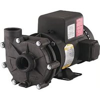
W16G07S8-32P - Pump Little Giant - Free user manual and instructions
Find the device manual for free W16G07S8-32P Little Giant in PDF.
| Product type | Submersible pump |
| Brand | Little Giant |
| Model | W16G07S8-32P |
| Power supply | 230 V single-phase, 50 Hz |
| Motor power | 1 HP (0.75 kW) |
| Max flow rate | Approx. 100 L/min |
| Max head | Approx. 50 m |
| Pump diameter | 4 inches (101.6 mm) |
| Discharge connection | 1 1/4 inch (31.75 mm) |
| Body material | Stainless steel |
| Check valve | Integrated, spring-loaded, removable |
| Electrical protection | Built-in surge arrester (stainless motor up to 5 HP) |
| Grounding | Mandatory (green wire) |
| Operating temperature | Up to 40 °C (water) |
| Installation | Vertical, submerged, at least 1.5 m from the bottom |
| Net weight | Approx. 10 kg |
| Warranty | 12 months |
| Maintenance | Check insulation and cable continuity |
| Safety | Do not run dry; cut power before servicing |
Frequently Asked Questions - W16G07S8-32P Little Giant
User questions about W16G07S8-32P Little Giant
0 question about this device. Answer the ones you know or ask your own.
Ask a new question about this device
Download the instructions for your Pump in PDF format for free! Find your manual W16G07S8-32P - Little Giant and take your electronic device back in hand. On this page are published all the documents necessary for the use of your device. W16G07S8-32P by Little Giant.
USER MANUAL W16G07S8-32P Little Giant
Franklin Electric Co., Inc.
www.franklinwater.com
customerservice@lgpc.com
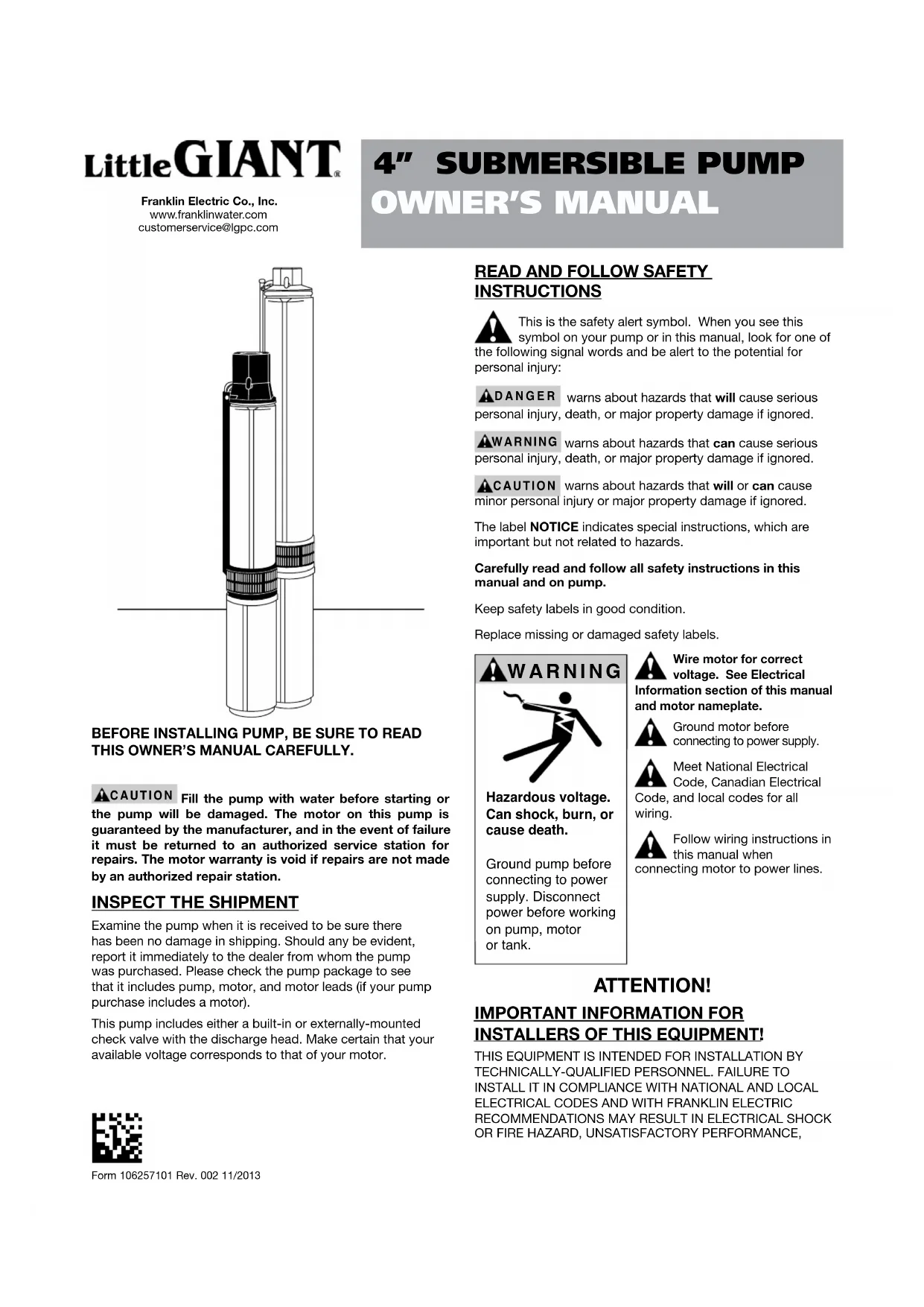
4" SUBMERSIBLE PUMP
OWNER'S MANUAL
natural_image
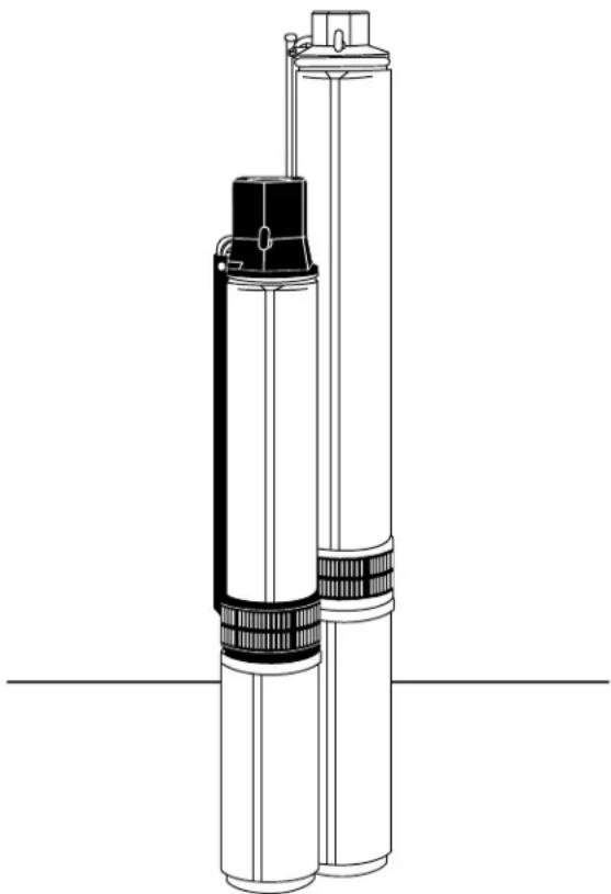
Technical line drawing of a cylindrical device with black and white components, no text or symbols presentBEFORE INSTALLING PUMP, BE SURE TO READ THIS OWNER'S MANUAL CAREFULLY.
CAUTION Fill the pump with water before starting or the pump will be damaged. The motor on this pump is guaranteed by the manufacturer, and in the event of failure it must be returned to an authorized service station for repairs. The motor warranty is void if repairs are not made by an authorized repair station.
INSPECT THE SHIPMENT
Examine the pump when it is received to be sure there has been no damage in shipping. Should any be evident, report it immediately to the dealer from whom the pump was purchased. Please check the pump package to see that it includes pump, motor, and motor leads (if your pump purchase includes a motor).
This pump includes either a built-in or externally-mounted check valve with the discharge head. Make certain that your available voltage corresponds to that of your motor.

Form 106257101 Rev. 002 11/2013
READ AND FOLLOW SAFETY INSTRUCTIONS
This is the safety alert symbol. When you see this symbol on your pump or in this manual, look for one of the following signal words and be alert to the potential for personal injury:
ADANGER warns about hazards that will cause serious personal injury, death, or major property damage if ignored.
WARNING warns about hazards that can cause serious personal injury, death, or major property damage if ignored.
ACAUTION warns about hazards that will or can cause minor personal injury or major property damage if ignored.
The label NOTICE indicates special instructions, which are important but not related to hazards.
Carefully read and follow all safety instructions in this manual and on pump.
Keep safety labels in good condition.
Replace missing or damaged safety labels.

text_image
WARNINGHazardous voltage. Can shock, burn, or cause death.
Ground pump before connecting to power supply. Disconnect power before working on pump, motor or tank.
Wire motor for correct voltage. See Electrical Information section of this manual and motor nameplate.
Ground motor before connecting to power supply.
Meet National Electrical Code, Canadian Electrical Code, and local codes for all wiring.
Follow wiring instructions in this manual when connecting motor to power lines.
ATTENTION!
IMPORTANT INFORMATION FOR INSTALLERS OF THIS EQUIPMENT!
THIS EQUIPMENT IS INTENDED FOR INSTALLATION BY TECHNICALLY-QUALIFIED PERSONNEL. FAILURE TO INSTALL IT IN COMPLIANCE WITH NATIONAL AND LOCAL ELECTRICAL CODES AND WITH FRANKLIN ELECTRIC RECOMMENDATIONS MAY RESULT IN ELECTRICAL SHOCK OR FIRE HAZARD, UNSATISFACTORY PERFORMANCE,
AND EQUIPMENT FAILURE. FRANKLIN ELECTRIC INSTALLATION INFORMATION IS AVAILABLE FROM PUMP MANUFACTURERS AND DISTRIBUTORS, AND DIRECTLY FROM FRANKLIN ELECTRIC. CALL FRANKLIN ELECTRIC TOLL FREE AT 800-701-7894 FOR INFORMATION. RETAIN THIS INFORMATION SHEET WITH THE EQUIPMENT FOR FUTURE REFERENCE.
WARNING
SERIOUS OR FATAL ELECTRICAL SHOCK MAY RESULT FROM FAILURE TO CONNECT THE MOTOR, CONTROL ENCLOSURES, METAL PLUMBING, AND ALL OTHER METAL NEAR THE MOTOR OR CABLE TO THE POWER SUPPLY GROUND TERMINAL USING WIRE NO SMALLER THAN MOTOR CABLE WIRES. TO REDUCE RISK OF ELECTRICAL SHOCK, DISCONNECT POWER BEFORE WORKING ON OR AROUND THE WATER SYSTEM. DO NOT USE MOTOR IN SWIMMING AREAS.
It is a good idea to keep an accurate record of your installation. Be sure to record the data below:
| Purchased from: | |||
| Date of installation: | |||
| Pump model*: | |||
| Pump date code*: | |||
| Well inside diameter (in/mm): | |||
| Depth of well (ft/m): | |||
| Depth of water (ft/m): | |||
| Pump setting (ft/m): | |||
| Drop pipe size: | |||
| Wire size (pump to control box): | |||
| Wire size (control box to power source): | |||
| Horizontal offset (between well & house): | |||
| Make of motor* | |||
| Amps HP | Volts Phase | ||
| Make of control box | |||
| HP Volts | |||
| Power supply | |||
| Volts HZ | |||
| Pressure switch limits | |||
| Cut-in (PSI) Cut-out | (PSI) | ||
*This information is on your pump or motor tag. It will help us identify your pump in case of later inquiries.
TEST RUNNING
If test running pump before installation:
- Ensure that the power supply corresponds with that shown on the nameplate of the motor and control box (if required).
- Install pump and components appropriate for the test as shown in Fig. 1.
- Make sure power supply is turned off and circuit breaker or disconnect switch is open. Make electrical connections appropriate to your motor as shown in Figure 2, 3 or 4.
- On a three-phase motor, use a magnetic starter equipped with quick-trip, ambient compensated heaters of correct size for the horsepower of the motor.
To ensure correct rotation of three-phase units, brace pump shell securely and apply power momentarily by snapping line switch quickly on and off. If rotation is correct, reaction of the shell will be clockwise when viewed from pump discharge (that is, pump shaft will rotate counter clockwise). Interchange any two leads at magnetic starter to reverse rotation.
- Run pump and motor unit for a few seconds to ensure that it is in working order.
text_image
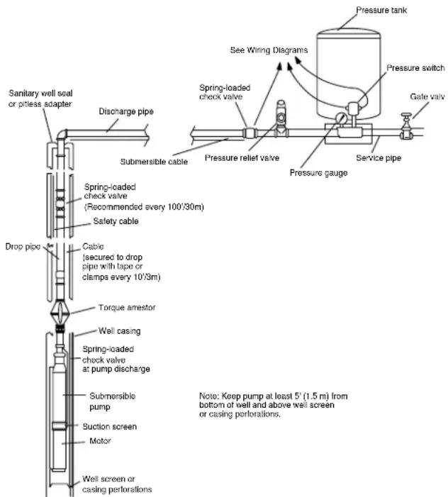
Sanitary well seal or pitless adapter Discharge pipe Submersible cable Spring-loaded check valve (Recommended every 100'30m) Safety cable Drop pipe Cable (secured to drop pipe with tape or clamps every 10'3m) Torque arrester Well casing Spring-loaded check valve at pump discharge Submersible pump Suction screen Motor Well screen or casing perforations See Wiring Diagrams Pressure relief valve Pressure gauge Pressure tank Pressure switch Gate valve Service pipeFIGURE 1 Installation Diagram
SUITABILITY OF WELL
Install the pump only in a well that has been properly developed. Water from an undeveloped well often contains an excessive amount of sand, dirt, and abrasives which can damage the pump. Check that the well is large enough to
allow the pump to be set at the required depth. Do not set the pump below the casing perforations or well screen unless you make arrangements to ensure an adequate flow of water over the motor for cooling purposes. Determine the correct pump setting from the driller's record by taking into account the static water level and the drawdown at the proposed pumping rate. Keep the pump at least five feet from the bottom of a drilled well.
Follow the instructions enclosed in the cable splicing kit (purchased separately).
DROP PIPE
Submersible drop pipe manufacturer's usage guidelines should always be followed when suspending a submersible pump in a well. Generally either galvanized steel or plastic are used for the pump drop pipe. When using plastic piping it is important to follow the manufacturer's depth and pressure rating. Give special consideration to:
- A safety cable to prevent loss of pump if pipe should break.
- A torque arrestor just above pump to prevent chafing the cable when pump and pipe twist during the starting and stopping cycle. (See Figure 1.)
Schedule 40 galvanized pipe is suitable for settings to 600 feet (180m). For deeper settings, use schedule 40 pipe for the bottom 600 feet (180m), and schedule 80 for the remainder.
NOTICE: Drop pipe sizes and usages depths should be considered as general guidelines only. Drop pipe manufacturer data and recommendations supersedes these instructions.
Take great care to keep pipes clean and free from pebbles, scale, and thread chips. Make sound, air-tight connections at all fittings. Pipe sealant is recommended.
CHECK VALVES
It is recommended that one or more check valves always be used in submersible pump installations. If the pump does not have a built-in check valve, an inline check valve should be installed in the discharge line within 25 feet of the pump and below the draw down level of the water supply. If permitted by local codes it is recommended that an additional check valve be installed in the system plumbing between the wellhead and the system's pressure tank. For pump installations that are more than 200 feet (60m) below the wellhead; additional check valves should be installed in the drop pipe. This should be done at intervals of 200 feet (60m) or at the check valve manufacturer's specified installation interval. More than one check valve is often needed, but more than the recommended number of check valves should not be used.
Swing type check valves are not acceptable and should never be used with submersible motors/pumps. Swing type check valves have a slower reaction time which can cause water hammer (see next page). Internal pump check valves or spring loaded check valves close quickly and help eliminate water hammer.
Check valves are used to hold pressure in the system when the pump stops. They also prevent backspin, water hammer and upthrust. Any of these can lead to early pump or motor failure.
NOTE: Only positive sealing check valves should be used in submersible installations. Although drilling the check valve or using drain-back check valves may prevent back spinning, they create upthrust and water hammer problems.
A. Backspin - With no check valve or a failed check valve, the water in the drop pipe and the water in the system can flow down the discharge pipe when the motor stops. This can cause the pump to rotate in a reverse direction. If the motor is started while it is back spinning, an excessive force is placed across the pump-motor assembly that can cause impeller damage, motor or pump shaft breakage, excessive bearing wear, etc.
B. Upthrust - With no check valve, a leaking check valve, or drilled check valve, the unit starts under a zero head condition. This causes an uplifting or upthrust on the impeller-shaft assembly in the pump. This upward movement carries across the pump-motor coupling and creates an upthrust condition in the motor. Repeated upthrust can cause premature failure of both the pump and the motor.
C. Water Hammer - If the lowest check valve is more than 30 feet above the standing (lowest static) water level, or a lower check valve leaks and the check valve above holds, a vacuum is created in the discharge piping. On the next pump start, water moving at very high velocity fills the void and strikes the closed check valve and the stationary water in the pipe above it, causing a hydraulic shock. This shock can split pipes, break joints and damage the pump and/or motor. Water hammer can often be heard or felt. When discovered, the system should be shut down and the pump installer contacted to correct the problem.
REMOVABLE POPPET CHECK VALVE
4" submersible pumps with a 1-1/4" discharge are supplied with a spring-loaded, removable poppet check valve assembly. This check valve can be removed from the pump discharge when drain back is desired.
WARNING
Fluid draining back through the pump can go to rotate backwards. If pump/motor starts, damage to the pump can occur.
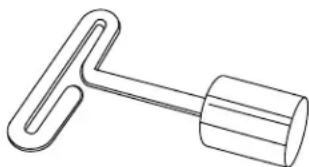
The check valve can be removed using a T-handle poppet wrench (purchased separately), or with standard needle-nosed pliers. The poppet assembly is left-hand threaded and is removed by turning clockwise.
When reinstalling a poppet check valve assembly, tighten it to 15 inch-pounds.
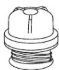
Poppet Assembly
natural_image
Simple line drawing of a mechanical tool or bracket (no text or symbols)T-Handle Poppet Wrench
INSTALLATION OF PUMP, DROP PIPE, AND ASSOCIATED EQUIPMENT
Figure 1 illustrates a typical well installation showing in ground components. Adhere to the following items when installing the pump and drop pipe:
- Fasten the submersible cable to the drop pipe with clamps or appropriate tape every 10 ft. (3m) to prevent tangling and
damage to the cable. The cable must remain slack when using plastic drop pipe to allow for stretching of pipe when installed in the well.
- Take care not to scrape or pinch the submersible cable against the well casing.
One sentence needs to be together on same page - Use an ohmmeter or megger to make insulation and continuity checks on the cable once the pump is installed. This locates any fault in the cable.
- Make sure a check valve is in accordance with the guidelines in this manual.
- Install a torque arrestor just above the pump to prevent chafing the cable when pump and pipe twist during starting and stopping.
- Attach a safety cable to pump to prevent loss of pump if pipe should break.
- Place a sanitary well seal or pitless adapter with an approved cover plate over top of well per manufacturers recommendations.
- Keep pump at least 5' (1.5m) from bottom of well and above well screen or casing perforations.
ELECTRICAL INFORMATION
- Employ a licensed electrician to perform the wiring. All wiring must be done in accordance with applicable national and local electrical codes.
- Check that the power supply corresponds with the electrical rating of the submersible motor and the control box (if required). Make sure that the control box electrical rating matches the motor electrical rating.
- Every installation requires a fused disconnect switch or circuit breaker.
- Every installation must be grounded. There must be a reliable ground connection between the pump and the distribution panel. The motor lead incorporates a green grounding conductor.
- Lightning arrestors are recommended for every installation. All stainless steel, single phase motors through 5CV have built-in lightning arrestors. 3-phase motors require a separate lightning arrestor installed as close to the wellhead as possible. Install the arrestor in accordance with manufacturer's recommendations. Lightning arrestors provide protection against only induced voltage surges on secondary power lines; they are not effective against direct hits.
- Mount the control box in an area protected from rain, snow, direct sunlight, or other high temperatures as this may cause tripping of the overload protector. Also protect the control box from extreme cold (below 25^ F/-32°C) as this may have adverse effects on the starting capacitor.
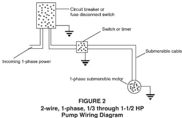
- A two-wire pump does not require a motor control box; all electrical components are built inside the motor. Figure 2 shows a typical wiring diagram for a two-wire installation.
text_image
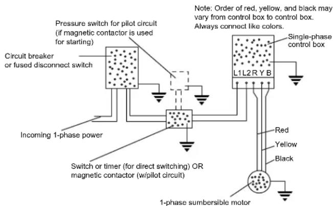
Circuit breaker or fuse disconnect switch Switch or timer Incoming 1-phase power Submersible cable 1-phase submersible motor FIGURE 2 2-wire, 1-phase, 1/3 through 1-1/2 HP Pump Wiring Diagram- A three-wire, 1-phase pump requires a motor control box incorporating overload relays. Figure 3 shows a typical wiring diagram for a three-wire, single-phase installation. Note that a magnetic contactor must be used if the pressure switch electrical rating is not sufficient to handle the submersible motor electrical rating. The pressure switch would then be incorporated into a pilot circuit to control the magnetic contactor. Make the connections at the control box in accordance with the wiring diagram in the control box to avoid damage to the motor.
text_image
Pressure switch for pilot circuit (if magnetic contactor is used for starting) Circuit breaker or fused disconnect switch Incoming 1-phase power Switch or timer (for direct switching) OR magnetic contactor (w/pilot circuit) Note: Order of red, yellow, and black may vary from control box to control box. Always connect like colors. L1L2RYB Single-phase control box Red Yellow Black 1-phase sumbersible motorFIGURE 3 3-wire, 1-phase, 1/3 through 15 HP Pump Wiring Diagram
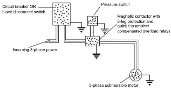
- A three-wire, three-phase pump does not require a motor control box. Figure 4 shows a typical wiring diagram for a three-wire, three-phase installation. A magnetic contractor with three-leg protection and quick-trip ambient compensated overload relays must be used.
flowchart
graph TD
    A["Circuit breaker OR fused disconnect switch"] --> B["Pressure switch"]
    B --> C["Magnetic contactor with 3-leg protection and quick-trip ambient compensated overload relays"]
    C --> D["3-phase submersible motor"]
    D --> E["Incoming 3-phase power"]
    style A fill:#f9f,stroke:#333
    style B fill:#ccf,stroke:#333
    style C fill:#cfc,stroke:#333
    style D fill:#fcc,stroke:#333
FIGURE 4 3-wire, 3-phase, 1-1/2 thru 50 HP Pump Wiring Diagram
- Use an ohm meter to make continuity and insulation checks after the installation is completed.
- Place the additional pump nameplate onto the submersible label and place both onto disconnect switch or circuit breaker box for future reference.
WELL TEST
Check the pump and well performance before making the final connection to the discharge system.
- Install a gate valve on the end of the pipe. Partially open the valve.
- Start the pump.
- Open the valve gradually to give full flow.
- If the discharge is not clear, let the pump run until water clears. If water does not clear in 30 minutes, stop the pump and take the necessary steps to correct the condition. After the water appears clear, check for sand by discharging into a clean bucket or suitable container.
- Close valve until maximum required system flow rate is obtained. This should correspond to the cut-in pressure of the pressure switch. Ensure that the output of the pump at this setting is not greater than the yield of the well. This can be checked by monitoring the well drawdown level and ensuring that the level is stable at the maximum required system flow rate.
CAUTION Never run the pump unless it is completely submerged in water. If run without water, the pump and motor could be damaged. Note also that air drawn into the pump can cause an airlock under certain conditions.
LOW-YIELDING WELL
A low-yielding well exists when the output from the pump is greater than the yield of the well. It can reduce the water level to the suction screen so that a mixture of air and water enters the pump. Pumping may stop since the pump cannot generate pressure with insufficient water. In this case, the column of water already in the drop pipe holds the check valve closed and an airlock may develop inside the pump. Because the conditions ensure neither adequate lubrication of the pump nor proper cooling for the motor, damage can result if power is not cut off quickly. Use one or more of the following methods to correct and/or protect this installation.
- Install an additional length of drop pipe to place pump lower in well if possible.
- Install a Franklin Pumptec or similar electronic drawdown sensor.
-
Install a floatless liquid level control. This device consists of an electrical relay activated by currents flowing through the ground-return circuits of electrodes hung in the well. The lower (stop) electrode, just above the pump, ensures that the water level can never be pumped down to the suction screen. The upper (start) electrode, just below the lowest static water level, ensures that the pump can start again as soon as the well has recovered. A floatless liquid level control works in series with the pressure switch. Refer to the manufacturers instructions provided with the control.
-
Install a flow control valve in the discharge line upstream from the pressure switch. This restricts the output from the pump without affecting the rate that water can be drawn from the pressure tank. Nevertheless, a heavy demand for water could empty the pressure tank, so a tank with a bonded diaphragm, air cell, or water bag is recommended.
- Install a smaller pump to avoid over-pumping the well. Have the dealer size the pump to the well yield.
- Install a low pressure cut off switch, or a pressure switch with such an arrangement built in. This protects a shallow-well pump from losing its prime, but it does not always provide satisfactory protection to a submersible pump from the effects of over-pumping the well. This is because it responds to a loss of pressure at the surface, which may occur after an air lock has formed inside the pump. Either a floatless liquid level control or a flow control valve, in that order, is recommended in preference to a low-pressure cutoff switch as protection against over-pumping.
DISCHARGE PLUMBING
Figure 1 illustrates a typical well installation showing above-ground components. Refer to Figure 1 and the following steps when installing the discharge plumbing.
- Install an above-ground check-valve upstream from the pressure switch.
- Always install a pressure relief valve in the system. The relief valve should be capable of discharging the flow rate of the pump at the rated working pressure of the pressure tank. Locate the relief valve close to the pressure tank.
- Install a pressure switch between the check valve and the pressure tank. Refer to Figure 2, 3, or 4 for proper wiring connections of pressure switch.
- Install a pressure tank as close as possible to the pressure switch. Refer to manufacturer's recommendations for installation.
INSTALLATION IN LAKE OR STREAM
A submersible pump is usually isolated at the bottom of a well, where electrical leakage from its motor and cable presents no hazard to life. This natural protection is lost when it is installed it in a lake, pond, stream, or fountain because there is no way to stop people and animals from entering or touching the surrounding water. It is recommended that such an installation be done by a licensed electrician in conformance with all applicable national and local electrical codes. Grounding as described in this manual is a minimum requirement, and a ground fault circuit interrupter (GFCI) is advisable. But in the absence of explicit national or local regulations, ask the local electric utility for guidance. In any case, support the pump from the shore or bottom at a 15^ slant to assure proper motor bearing lubrication. Shield the pump from direct physical contact by people and animals. Protect and screen the pump intake to prevent blockage by leaves and weeds, but remember the need for adequate flow over the motor for cooling purposes. In addition, protect the entire underwater installation from water currents, ice, boats, anchors, debris, vandalism, and other hazards.
TROUBLESHOOTING
1. PUMP FAILS TO START
a) Electrical trouble - call dealer or electrician
b) Drawdown protection device has pump turned off
c) Overload tripped
d) Reset low pressure cutoff switch (if installed)
2. PUMP FAILS TO DELIVER WATER
a) Air lock in pump
b) Clogged intake screen
c) Insufficient well yield
3. PUMP GIVES REDUCED OUTPUT
a) Insufficient well yield
b) Worn pump
c) Clogged intake screen
d) Low voltage
e) Incorrect rotation (3-phase only)
4. PUMP CYCLES TOO FREQUENTLY
a) Excessive pressure drop between pressure switch and pressure tank
b) Cut-in pressure at pressure tank too high
c) Cut-out pressure at pressure tank too low
d) Waterlogged pressure tank
e) Start and stop electrodes of floatless liquid level control set too close together
f) Tank sized too small to meet system requirements
5. OVERLOADS TRIP
a) Electrical trouble - call dealer or electrician
6. PRESSURE SWITCH CYCLES RAPIDLY WHEN PUMP STARTS
a) Pressure switch too far from pressure tank
b) Improper air charge of tank - adjust to manufacturer's recommendations
LittleGIANT®
Franklin Electric Co., Inc.
www.franklinwater.com customerservice@lgpc.com
4" POMPES SUBMERSIBLES
MANUEL DU PROPRIETAIRE

natural_image
Technical line drawing of a cylindrical mechanical device with black and white components (no text or symbols)LIRE ATTENTIVEMENT CE GUIDE D'UTILISATION AVANT D'INSTALLER LA POMPE.
natural_image
Simple line drawing of a mechanical lever or handle (no text or symbols)3. DÉBIT FAIBLE PRODUIT PAR LA POMPE
Franklin Electric Co., Inc.
www.franklinwater.com
customerservice@lgpc.com
4" BOMBA SUMERGIBLE
MANUAL DEL PROPIETARIO
natural_image
Technical line drawing of a cylindrical mechanical device with black and white components (no text or symbols)ANTES DE INSTALAR LA BOMBA, ASEGÚRESE DE LEER ATENTAMENTE ESTE MANUAL DEL PROPIETARIO.
PRECAUCIÓN
natural_image
Two technical line drawings of mechanical components: a threaded cap and a U-shaped tool (no text or symbols)Franklin Electric Company, Inc. and its subsidiaries (hereafter “the Company”) warrants that the products accompanied by this warranty are free from defects in materials or workmanship of the Company that exist at the time of sale by the Company and which occur or exist within the applicable warranty period. Any distributor, sub-distributor, recipient, end-user and/or consumer agrees that by accepting the receipt of the products, the distributor, sub-distributor, recipient, end user and/or consumer expressly agrees to be bound by the terms of the warranty set forth herein.
I. Applicable Warranty Period
The products accompanied by this warranty shall be covered by this Limited Warranty for a period of 12 months from the date of original purchase by the consumer. In the absence of suitable proof of purchase date, the warranty period of this product will begin to run on the product's date of manufacture.
II. Instructions Applicable to this Limited Warranty
- Consumers wishing to submit a warranty claim must return the products accompanied by this warranty to the point of purchase for warranty consideration.
- Upon discovery of a defect, any personal injury, property damage or any other type of resulting damage, if applicable, shall be reasonably mitigated to the extent possible.
- At its discretion, the Company may inspect products either at its facilities or in the field, and after determination of a warranty claim, will, at its option, repair or replace defective parts. Repaired or replaced parts will be returned freight prepaid by the Company.
- This warranty policy does not cover any labor or shipping charges. The Company shall not be liable for any costs or charges attributable to any product testing, maintenance, installation, repair or removal, or for any tools, supplies, or equipment needed to install, repair, or remove any product.
III. Limitations Applicable to this Limited Warranty
THIS WARRANTY DOES NOT APPLY TO ANY OF THE FOLLOWING:
- Any product that is not installed, applied, maintained and used in accordance with the Company's published instructions, applicable codes, applicable ordinances and/or with generally accepted industry standards.
- Any product that has been subject to misuse, misapplication, neglect, alteration, accident, abuse, tampering, acts of God (including lightning), acts of terrorism, acts of war, fire, improper storage or installation, improper use, improper maintenance or repair, damage or casualty, or to an excess of the recommended maximums as set forth in the product instructions.
- Any product that is operated with any accessory, equipment, component, or part not specifically approved by the Company.
- Use of replacement parts not sold by the Company, the unauthorized addition of non-Company products to other Company products, and the unauthorized alteration of Company products.
-
Products damaged by normal wear and tear, normal maintenance services and the parts used in connection with such service, or any other conditions beyond the control of the Company.
-
Anyproduct that has been used for purposes other than those for which it was designed and manufactured.
- Any use of the product where installation instructions and/or instructions for use were not followed.
The Company reserves the right at any time, and from time to time, to make changes in the design and/or improvements upon its product without thereby imposing any obligation upon itself to make corresponding changes or improvements in or upon its products already manufactured and/or previously sold. The Company further reserves the right to substitute parts or components of substantially equal quality in any warranty service required by operation of this Limited Warranty.
This written Limited Warranty is the entire warranty authorized and offered by the Company. There are no warranties or representations beyond those expressed in this document.
THIS WARRANTY AND REMEDY IS IN LIEU OF ALL OTHER WARRANTIES AND REMEDIES INCLUDING WITHOUT LIMITATION, WARRANTIES OF MERCHANTABILITY AND/OR FITNESS FOR A PARTICULAR PURPOSE, WHICH ARE HEREBY SPECIFICALLY DISCLAIMED AND EXPRESSLY EXCLUDED. CORRECTION OF NON-CONFORMITIES, IN THE MANNER AND FOR THE PERIOD OF TIME AS SET FORTH ABOVE, SHALL CONSTITUTE FULFILLMENT OF ALL LIABILITY OF THE COMPANY TO THE PURCHASER WHETHER BASED ON CONTRACT, NEGLIGENCE, OR OTHERWISE.
THE COMPANY SHALL NOT BE LIABLE FOR INCIDENTAL, CONSEQUENTIAL OR SPECIAL DAMAGES SUCH AS, BUT NOT LIMITED TO:
DAMAGE TO OR LOSS OF OTHER PROPERTY OR EQUIPMENT, LOSS OF USE OF EQUIPMENT, FACILITIES OR SERVICE, LOSS OF PROFIT OR SALES, COST OF PURCHASES OR REPLACEMENT GOODS, CLAIMS OF CUSTOMERS OF THE PURCHASER, FAILURE TO WARN AND/OR INSTRUCT, LOSS OF OTHER PRODUCTS, OR COSTS OF ENVIRONMENTAL REMEDIATION, OR DIMINUTION IN PROPERTY VALUE. THE REMEDIES OF THE PURCHASER SET FORTH HEREIN ARE EXCLUSIVE, AND THE LIABILITY OF THE COMPANY SHALL NOT, EXCEPT AS EXPRESSLY PROVIDED HEREIN, EXCEED THE PRICE OF THE PRODUCTS UPON WHICH SUCH LIABILITY IS BASED. DAMAGES AS SET FORTH IN THIS PARAGRAPH SHALL BE REASONABLY MITIGATED TO THE EXTENT POSSIBLE. THIS PARAGRAPH SHALL ALSO APPLY TO ALL DAMAGES RESULTING FROM CONDITIONS SET FORTH IN SECTION III ABOVE AND (1) DEFECTS IN PRODUCT PROTOTYPES OR REPLACEMENT PART PROTOTYPES THAT HAVE NOT BEEN PUT INTO PRODUCTION, CIRCULATED AND SOLD BY THE COMPANY, AND/OR (2) DEFECTS THAT WERE NOT FOUND AT THE TIME OF SALE DUE TO SCIENTIFIC AND TECHNOLOGICAL REASONS.
This Limited Warranty gives you specific legal rights. You may have other rights, which vary according to the applicable laws and regulations. Where any term of this warranty is prohibited by such laws, it shall be null and void, but the remainder of this warranty shall remain in full force and effect.
DISCLAIMER: Any oral statements about the product made by the seller, the Company, the representatives or any other parties, do not constitute warranties, shall not be relied upon by the user, and are not part of the contract for sale. Seller's and the Company's only obligation, and buyer's only remedy, shall be the replacement and/or repair by the Company of the product as described above. Before using, the user shall determine the suitability of the product for his intended use, and user assumes all risk and liability whatsoever in connection therewith.
GARANTIE LIMITÉE LA PRÉSENTE GARANTIE ÉNONCE LA SEULE OBLIGATION DE LA SOCIÉTÉ ET LE RECOURS EXCLUSIF DE L'ACHETEUR POUR UN PRODUIT DÉFECTUEUX.
For technical assistance, please contact 1.800.701.7894
customerservice@lgpc.com