WRS5 - Pump Little Giant - Free user manual and instructions
Find the device manual for free WRS5 Little Giant in PDF.
| Product type | Waste water pump |
| Brand | Little Giant |
| Model | WRS5 |
| Nominal voltage | 115 V |
| Motor power | 1/6 HP |
| Frequency | 60 Hz |
| Current | 2 A |
| Power consumption | 380 W |
| Shut-off height | 21 ft (6.4 m) |
| Max liquid temperature | 51.7 °C (125 °F) |
| Compatible liquids | Waste water (no sewage, no solids) |
| Filtration | Inlet screen retaining particles > 1/8 in |
| Installation | Under sink, gravity fed |
| Inlet connection | 1½ in MNPT (2 in adapter included) |
| Outlet connection | 2 in MNPT (1½ in adapter included) |
| Discharge | Check valve required |
| Ventilation | 2 in vent pipe (1½ in adapter included) |
| Electrical protection | GFCI required, grounded |
| Warranty | 1 year from purchase |
| Maintenance | Regular cleaning of screen and tank |
Frequently Asked Questions - WRS5 Little Giant
User questions about WRS5 Little Giant
0 question about this device. Answer the ones you know or ask your own.
Ask a new question about this device
Download the instructions for your Pump in PDF format for free! Find your manual WRS5 - Little Giant and take your electronic device back in hand. On this page are published all the documents necessary for the use of your device. WRS5 by Little Giant.
USER MANUAL WRS5 Little Giant
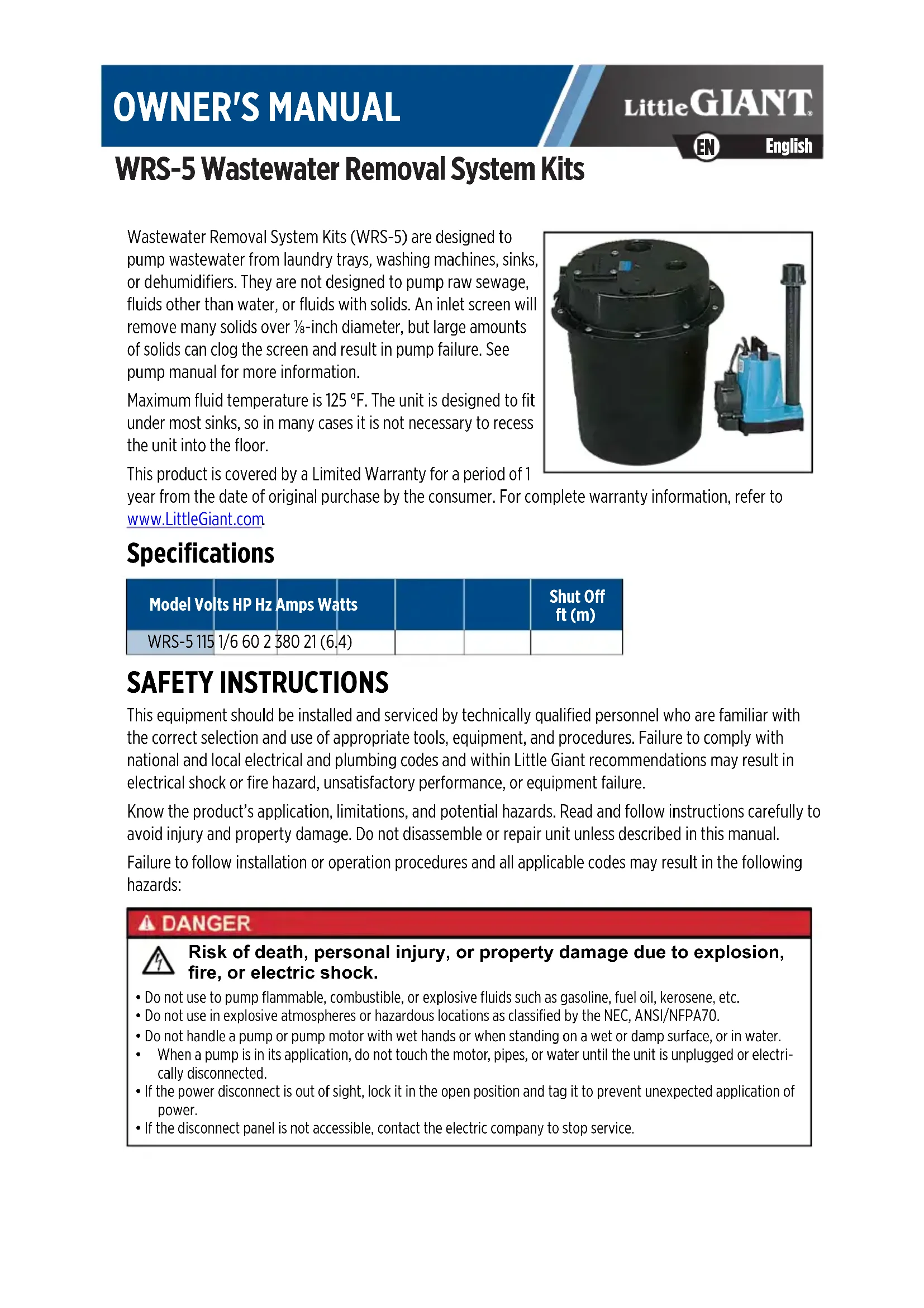
WRS-5 Wastewater Removal System Kits
Wastewater Removal System Kits (WRS-5) are designed to pump wastewater from laundry trays, washing machines, sinks, or dehumidifiers. They are not designed to pump raw sewage, fluids other than water, or fluids with solids. An inlet screen will remove many solids over 18 -inch diameter, but large amounts of solids can clog the screen and result in pump failure. See pump manual for more information.
Maximum fluid temperature is 125^ F. The unit is designed to fit under most sinks, so in many cases it is not necessary to recess the unit into the floor.
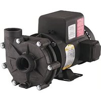
natural_image
Black cylindrical industrial component with attached blue hydraulic pump (no visible text or symbols)This product is covered by a Limited Warranty for a period of 1
year from the date of original purchase by the consumer. For complete warranty information, refer to www.LittleGiant.com
Specifications
| Model Volts HP Hz Amps Watts | Shut Off ft (m) | |||||
| WRS-5 115 | 1/6 | 60 | 2 380 | 21 (6.4) | ||
SAFETY INSTRUCTIONS
This equipment should be installed and serviced by technically qualified personnel who are familiar with the correct selection and use of appropriate tools, equipment, and procedures. Failure to comply with national and local electrical and plumbing codes and within Little Giant recommendations may result in electrical shock or fire hazard, unsatisfactory performance, or equipment failure.
Know the product's application, limitations, and potential hazards. Read and follow instructions carefully to avoid injury and property damage. Do not disassemble or repair unit unless described in this manual.
Failure to follow installation or operation procedures and all applicable codes may result in the following hazards:
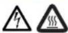
DANGER

Risk of death, personal injury, or property damage due to explosion, fire, or electric shock.
- Do not use to pump flammable, combustible, or explosive fluids such as gasoline, fuel oil, kerosene, etc.
- Do not use in explosive atmospheres or hazardous locations as classified by the NEC, ANSI/NFPA70.
- Do not handle a pump or pump motor with wet hands or when standing on a wet or damp surface, or in water.
- When a pump is in its application, do not touch the motor, pipes, or water until the unit is unplugged or electrically disconnected.
- If the power disconnect is out of sight, lock it in the open position and tag it to prevent unexpected application of power.
- If the disconnect panel is not accessible, contact the electric company to stop service.
▲ WARNING

Risk of severe injury or death by electrical shock.
- To reduce risk of electrical shock, disconnect power before working on or around the system. More than one disconnect switch may be required to de-energize the equipment before servicing.
- Wire pump system for correct voltage.
- Be certain that this pump is connected to a circuit equipped with a ground fault circuit interrupter (GFCI) device if required by code.
- Some pumps are supplied with a grounding conductor and grounding-type attachment plug. To reduce risk of electric shock, be certain that it is connected only to a properly grounded grounding-type receptacle. Do not remove the third prong from the plug, or cut plug from cord. The third prong is to ground the pump to help prevent possible electric shock hazard.
- Check local electrical and building codes before installation. The installation must be in accordance with their regulations as well as the most recent National Electrical Code (NEC) and the Occupational Safety and Health Act (OSHA).
- Do not use the power cord for lifting the pump.
- Do not use an extension cord.
- The pump should only be used with liquids compatible with pump component materials. If the pump is used with liquids incompatible with the pump components, the liquid can cause failure to the electrical insulation system resulting in electrical shock.
- Under no circumstances should the junction box be located where it may become flooded or submerged by water.
- Any splice between the pump and the control panel must be made within a junction box mounted outside of the basin and comply with the National Electrical Code.
CAUTION


Risk of bodily injury, electric shock, or equipment damage.
- This equipment must not be used by children or persons with reduced physical, sensory or mental abilities, or lacking in experience and expertise, unless supervised or instructed. Children may not use the equipment, nor may they play with the unit or in the immediate vicinity.
- Equipment can start automatically. Lockout-Tagout before servicing equipment.
- An inoperative or malfunctioning pump could lead to flooding, resulting in personal injury or property damage.
- Operation of this equipment requires detailed installation and operation instructions provided in this manual. Read entire manual before starting installation and operation. End User should receive and retain manual for future use.
- Keep safety labels clean and in good condition.
- Keep work area clean, well-lit, and uncluttered.
- Wear safety glasses while installing or performing maintenance on the pump.
NOTICE
Risk of damage to pump or other equipment.
- Support pump and piping when assembling and when installed. Failure to do so may cause piping to break, pump to fail, motor bearing failures, etc.
- Do not install the pump in a manner that will subject it to splashing or spraying.
- Periodically inspect pump and system components. Regularly check hoses for weakness or wear, making certain that all connections are secure.
- Schedule and perform routine maintenance as required and in accordance with the Maintenance section of this manual.
INSTALLATION Typical Installation
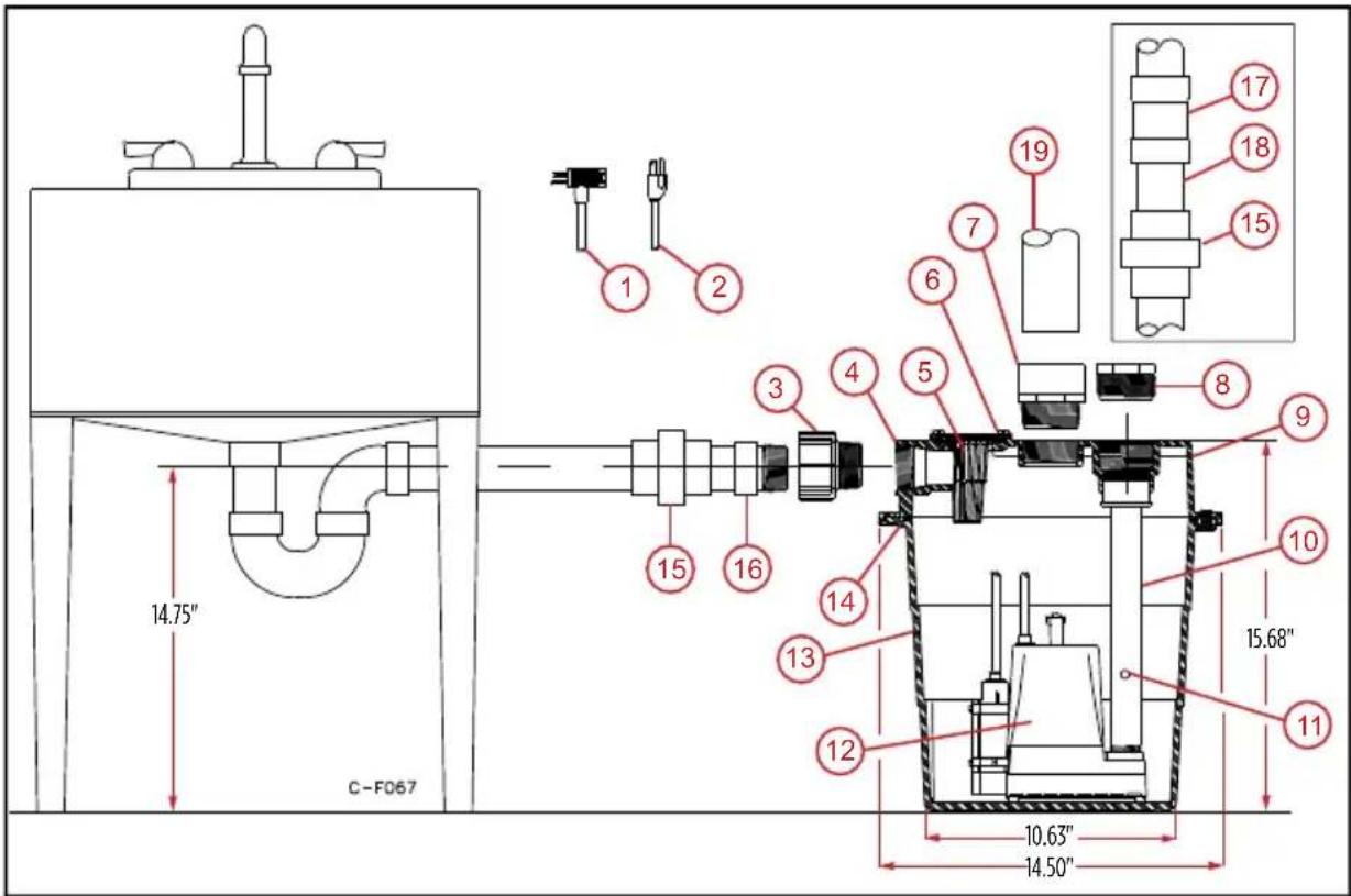
text_image
14.75" C-F067 10.63" 14.50" 15.68" 12 11 13 14 15 16 15 16 3 4 5 6 7 8 9 10 11 12 13 14 15 16 17 18 19-
Automatic switch cord (2-hole cord grommet included)
-
Filter access cover with O-Ring
-
38 -inch bleed hole 16. *Intake
-
Power cord 7. Vent adapter 12. Pump 17. *Check valve
-
Inlet adapter
-
Discharge adapter
-
Basin
-
*Discharge pipe
-
Basin inlet
-
Basin cover
-
Cover O-Ring
-
*Basin vent pipe
-
Filter
-
Discharge pipe
-
*Union
*Items not included with WRS-5 Basin kit
Pump Location
- Locate unit so that inlet is gravity-fed. Unit will not draw water up from a lower level.
- Ensure that the total assembly rests flat on a level surface.
- Keep basin away from any item that could puncture it.
- Position selected should be convenient to inlet, discharge, and vent piping, and electrical supply.
Inlet Piping
- Plumb inlet to basin cover fitting using 1½-inch threaded pipe.
- Do not reduce the sizing.
- Install a P-trap and a union next to the basin.
- Hand tighten plastic fittings.
- Use pipe joint compound.
NOTE: A 1½ MNPT x 2-inch slip pipe adapter is provided if a 2-inch inlet is required.
Discharge Piping
- Plumb discharge to basin cover fitting using 2-inch threaded pipe.
- Use a union and a swing check valve no more than 3 inches (7.6 cm) from top of basin cover.
- Install check valve in proper flow direction.
- No water will flow out of unit if check valve is installed backwards.
- Seal discharge piping with pipe joint compound.
- Verify lift height of pump is not exceeded.
- Hand tighten plastic fittings.
NOTE: A 2 MNPT x 1½ FNPT reducer bushing is provided if a 1½-inch discharge is required.
Vent Piping
The basin must be vented in accordance with state and local codes.
IMPORTANT: Do not use a mechanical vent or restrict the vent because it will cause improper switch operation.
- Plumb vent to fitting in basin cover using 2-inch threaded pipe.
- Hand tighten plastic fittings.
- Use pipe joint compound.
NOTE: A 2 MNPT x 1½-inch slip pipe adapter is provided if a 1½-inch vent is required.
Electrical Connections
▲ WARNING

Risk of severe injury or death by electrical shock.
- Connect to a circuit equipped with a ground fault circuit interrupter (GFCI) if required by code.
Connect the power cord to a constant source of power matching the pump nameplate voltage.
- Connect the pump to its own circuit, with no other electric receptacles or equipment in the circuit.
- Ensure that the fuses or circuit breaker are of ample capacity in the electrical circuit.
- If installed in basement, locate plug connection four feet or more above floor, especially if basement floods.
Some pumps are supplied with a 3-prong electrical plug.
- Plug into a grounded receptacle with vent tube pointed down.
- Ensure vent tube remains unobstructed for proper pump operation.
- Secure power cord to piping with ties or tape.
IMPORTANT: If the plug is cut or the cord is shortened, then the warranty will be void.
Wires are color coded as follows:
| Color Wire Type | |
| Green/Yellow Ground | |
| Brown | LineBlue/White |
| Brown/Black | |
Operation Testing
- Fill unit with water through inlet.
- Verify that the pump starts when the water reaches 6 to 9 inches (15.2 to 22.9 cm).
- Verify that the pump stops when the water reaches 1 to 4 inches (2.5 to 10.2 cm).
MAINTENANCE
CAUTION
Risk of bodily injury, electric shock, or equipment damage.
- Before performing any maintenance, shut off water inlet and disconnect power cord from supply outlet.
- Pump may become hot during operation. Allow pump to cool before servicing.
Cleaning the Basin Screen
- Remove the four screen cover plate screws, plastic cover plate, seal ring, and screen.
- Clean inlet screen using a mild detergent and water.
- Examine O-ring. If deformed, replace.
Cleaning the Basin
- Remove the screws from cover.
- Remove the cord grommet.
- Loosen cords to allow slack.
- Remove cover.
- Remove pump.
- Clean basin using a mild detergent and water.
-
Reassemble in reverse order.
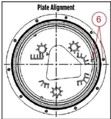
-
Be sure the pump alignment plate's mounting holes are properly aligned with the locating rib on the inside of the basin.
- Tighten cover screws to a torque of 18–20 in-lbs.
Cleaning the Pump
- Remove pump.
- Pull off the pressed-in screen.
- Remove the six base screws.
- Remove plastic pump base to clean around impeller and inside base.
IMPORTANT: Do not remove the impeller.
- Clean parts using a mild detergent and water.
-
Reinstall the base.
-
Be sure seal ring is seated properly in groove.
-
Tighten screws to a torque of 10–15 in-lbs.
-
Reinstall the pump screen and pump.
text_image
Plate Alignment 6Replacement Parts
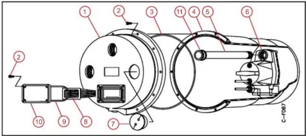
text_image
1 2 3 11 4 5 6 7 8 9 10 C-F067| Item Description Order Number | ||
| 1 Basin Cover 113130 | ||
| 2 Screw, 14'' -20 x 58'' (Qty: 14) 901709 | ||
| 3 Seal Ring 924065 | ||
| 4 Basin 113129 | ||
| 5 Discharge Pipe 10000014953 | ||
| 6 Pump 505715 | ||
| 7 2 Hole Cord Grommet 925011 | ||
| 8 Intake Screen 113131 | ||
| 9 O-Ring; Buna-N, 2-339 924066 | ||
| 10 Cover Plate, Screen 113132 | ||
| 11 | O-Ring; Buna-N, 2-131 | 924047 |
| - | Alignment Plate | 113145 |
Troubleshooting
| Problem | Probable Causes Corrective Action | |
| Pump will not shut off | Diaphragm switch Replace switch. | |
| Weak or hardened rubber diaphragm | Replace rubber diaphragm. | |
| Plugged vent tube Clear vent tube of any obstructions. | ||
| Dirt or sediment lodged between retainer ring and rubber diaphragm causing contacts to remain closed | Clean area around rubber diaphragm. | |
| Pump is air locked | Shut power off for approximately 1 minute. Then restart. Repeat several times to clear air from pump. If system includes a check valve, drill a 3/_16 -inch hole in discharge pipe approximately 2 inches above discharge connections. | |
| Liquid inflow matches pump capacity | Larger pump required. | |
| Defective switch | Disconnect switch. Check w/ohmmeter. Open-infinitive resistance, closed-zero. | |
| Loose connection in level control wiring | Check control wiring. | |
| Pump runs but does not discharge liquid. | Check valve installed backwards | Check flow indicating arrow on check valve body to insure it is installed properly. |
| Check valve stuck or plugged Remove check valve and inspect for proper operation. | ||
| Lift too high for pump Check rating table | ||
| Inlet to impeller plugged Pull pump and clean. | ||
| Pump is air locked | Shut power off for approximately 1 minute. Then restart. Repeat several times to clear air from pump. If system includes a check valve, drill a 3/_16 -inch hole in discharge pipe approximately 2 inches above discharge connections. | |
| Pump does not deliver rated capacity. | Lift too high for pump Check rated pump performance. | |
| Low voltage, speed too slow | Check for proper supply voltage to make certain it corresponds to nameplate voltage. | |
| Impeller or discharge pipe is clogged | Pull pump and clean. Check pipe for scale or corrosion. | |
| Impeller wear due to abrasives Replace worn impeller. | ||
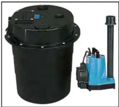
natural_image
Two industrial equipment components: a black cylindrical tank and a blue hydraulic pump with a vertical cylinder (no visible text or symbols)natural_image
Two industrial equipment components: a black cylindrical tank and a blue hydraulic pump with a vertical cylinder (no visible text or symbols)*Items not included with WRS-5 Basin kit