OPWG-71 - Pump Little Giant - Free user manual and instructions
Find the device manual for free OPWG-71 Little Giant in PDF.


User questions about OPWG-71 Little Giant
0 question about this device. Answer the ones you know or ask your own.
Ask a new question about this device
Download the instructions for your Pump in PDF format for free! Find your manual OPWG-71 - Little Giant and take your electronic device back in hand. On this page are published all the documents necessary for the use of your device. OPWG-71 by Little Giant.
USER MANUAL OPWG-71 Little Giant
Franklin Electric Co., Inc.
P. O. Box 12010
Oklahoma City, OK 73157-2010
405.947.2511 • Fax: 405.947.8720
www.LittleGiantPump.com
CustomerService-WTS@fele.com
OPWG SERIES OUT-OF-POND WATER GARDEN PUMP
POMPE NON SUBMERSIBLE
POUR BASSIN DE JARDIN
SÉRIE OPWG
BOMBA FUERA DE ESTANQUE
PARA JARDIN ACUÁTICO
GB INTRODUCTION
This instruction sheet provides you with the information required to safely own and operate your Little Giant pump. Retain these instructions for future reference.
The Little Giant pump you have purchased is of the highest quality workmanship and material, and has been engineered to give you long and reliable service. Little Giant pumps are carefully tested, inspected, and packaged to ensure safe delivery and operation. Please examine your pump carefully to ensure that no damage occurred during shipment. If damage has occurred, please contact the place of purchase. They will assist you in replacement or repair, if required.
READ THESE INSTRUCTIONS CAREFULLY BEFORE ATTEMPTING TO INSTALL, OPERATE, OR SERVICE YOUR LITTLE GIANT PUMP. KNOW THE PUMP'S APPLICATION, LIMITATIONS, AND POTENTIAL HAZARDS. PROTECT YOURSELF AND OTHERS BY OBSERVING ALL SAFETY INFORMATION. FAILURE TO COMPLY WITH THESE INSTRUCTIONS COULD RESULT IN PERSONAL INJURY AND/OR PROPERTY DAMAGE!
SAFETY GUIDELINES

WARNING
Ensure that the pump is disconnected from the power source before attempting to service or remove any component.
This pump is not submersible.
Do not handle a pump or pump motor with wet hands or when standing on a wet or damp surface, or in water.
This pump is supplied with a grounding conductor and/or grounding-type attachment plug. To reduce the risk of electric shock, ensure that it is connected to a properly-grounded, grounding-type receptacle.
In any installation where property damage and/or personal injury might result from an inoperative or leaking pump due to power outages, discharge line blockage, or any other reason, use a backup system and/or alarm.
Support the pump and its piping during assembly and after installation. Failure to do so may cause damage to the pump and/or piping.
ELECTRICAL CONNECTIONS

WARNING
This pump must be installed by qualified personnel, following all local electrical and safety codes, as well as the National Electrical Code (NEC) and the Occupational Safety and Health Act (OSHA).
Check the pump label for proper voltage required. Do not connect the pump to any voltage other than that shown.
If your pump is equipped with a 3-prong electrical plug, the third prong grounds the pump to prevent possible electrical shock hazard. Do not remove the third prong from the plug. A separate branch circuit is recommended. Do not use an extension cord when connecting the pump to its power source.
Refer to Table 1 to determine proper voltage. The pumps are pre-configured at the factory for 115V operation. If 230V operation is required, refer to the label on the motor for directions on wiring the pump. BE SURE OF PROPER ROTATION. IMPROPER ROTATION WILL SEVERELY DAMAGE THE PUMP AND VOID THE WARRANTY.
MATERIALS OF CONSTRUCTION
Volute Glass-filled polypropylene
Impeller ....Glass-filled Noryl®
Drain plug...... Glass-filled polypropylene
Bracket Glass-filled polypropylene
Seal (impeller) Ceramic & Buna-N
Seal (shaft) Carbon face
O-rings...... Buna-N
Hardware....Stainless steel
LEAF BASKET (OPTIONAL)
Little Giant offers an optional leaf basket for use with the OPWG pumps. The leaf basket is important for providing filtration to the water in the pond and keeping large debris from going into the pump. The leaf basket is a necessity for installations where the pump is located above the water source (Figure 3). The leaf basket is ready for assembly with any of the OPWG series pumps.
INSTALLATION

WARNING
PLEASE READ ALL INSTRUCTIONS BEFORE OPERATING THE OUT-OF-POND WATER GARDEN PUMP. The Out-Of-Pond Water Garden Pump is not self-priming; therefore, if the water source is below the pump, a foot valve must be installed and the pump should be primed prior to startup. Do not restrict the intake of the pump. Do not pump water with temperatures above 95°F. Pipe used for connecting to the intake side of the pump should not be of smaller inside diameter than that of the intake thread designation. THIS PUMP IS NOT SUBMERSIBLE.
NOTE: IT IS IMPORTANT TO LOCATE THE PUMP AS CLOSE AS POSSIBLE TO THE WATER SOURCE. THIS WILL KEEP THE INTAKE PIPING AT A MINIMUM LENGTH. USING LONGER SECTIONS OF PIPE AND ADDITIONAL ELBOWS WILL ADD ADDITIONAL FRICTION LOSSES AND COULD AFFECT THE PRIMING CAPABILITY AND PERFORMANCE OF THE PUMP.
- Determine a suitable, permanent location near the water source (pond, skimmer, filter, etc.) to mount the pump. There are 3 installation options available for the Out-Of-Pond Water Garden Pump (Figures 2-4).
- Mount the motor base on a hard, level foundation for all mounting installations. DO NOT install pump below ground level or in a low-lying area where flooding could occur. Make sure that the mounting surface has adequate drainage so that water will not collect around the pump and motor housing. If possible, when installing the pump, place a protective barrier over the pump to protect the motor from heavy rainfall, which could damage the motor and possibly cause electric shock. This barrier should also allow clearance around pump motor for air circulation.
- Determine what type of water feature will be used with the pump and determine its location in reference to the pump. Perform a preliminary layout of the piping and adapters to determine the proper length of the pipe sections. Minimize the number of elbows used in the intake and discharge lines. This will reduce the friction losses and maximize the pump performance. The intake line coming from the water source should be kept at a minimum length. Once the layout is determined for the water garden pond, begin making the permanent connections for the fittings.
- Use only plastic PVC-type fittings on both the pump intake and discharge (Table 1). All piping should be 2" PVC or flexible type piping. All threaded connections should be sealed with Teflon tape and the slip-fit piping connections should be sealed with PVC cement. Use compatible cement when connecting PVC piping to PVC adapters or PVC adapters to flexible piping. All piping should be supported and arranged for ease of alignment to the intake and discharge ports on the pump (or with the optional leaf basket). Forcing alignment of the piping to the intake and discharge ports on the pump volute can cause damage to the volute/leaf basket.
- The Out-Of-Pond Water Garden Pumps are not self-priming. DO NOT RUN THE PUMP DRY. A flooded intake is recommended for optimum performance because it eliminates the risk of running the pump dry or losing prime. THE LEAF BASKET AND ALL HARD PIPING DOWN TO THE FOOT/CHECK VALVE MUST BE FILLED WITH WATER BEFORE RUNNING THE PUMP.
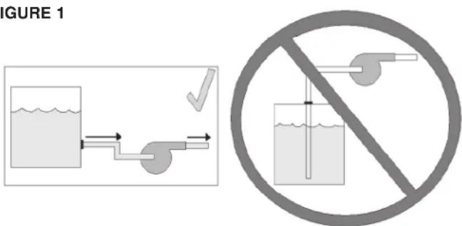
- For in-line use, install the pump so that the pump head (volute) is flooded when the pump is started. That is, the inlet of the pump must be below the level of the surface of the liquid being pumped (Figure 1).
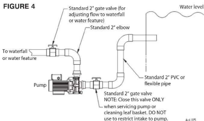
When installing the pump above water level, use a foot valve or check valve on the piping leading to the intake of the pump for pumping from the water source (pond, skimmer, filter, etc.) The foot/check valve will maintain the water in the intake line when the pump is not in operation. Figures 2-4 outline some typical installations for the Out-of-Pond Water Garden Pumps. (See Table 1 for pump intake and discharge sizes.)
- For all installations, an adjustable ball/gate valve should be used above the discharge of the pump. The ball/gate valve helps control the water flow for the water feature being used. When the pump is being serviced, be sure to close off the ball/gate valve to prevent back-flowing of the water from the waterfall/water feature.
- When installing the pump below water level, an additional ball/gate valve should be installed in the line ahead of the intake or leaf basket so that water flow from the water source can be shut-off for pump maintenance and/or cleaning the leaf basket screen. DO NOT USE THIS VALVE TO RESTRICT THE PUMP INTAKE.
FIGURE 1
text_image
FIGURE 1 ✓ No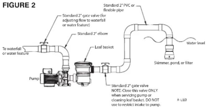
text_image
FIGURE 2 Standard 2" gate valve (for adjusting flow to waterfall or water feature) Standard 2" elbow To waterfall or water feature Pump Leaf basket Standard 2" PVC or flexible pipe Water level Skimmer, pond, or filter Standard 2" gate valve NOTE: Close this valve ONLY when servicing pump or cleaning leaf basket. DO NOT use to restrict intake to pump. A-L132WATER LEVEL ABOVE PUMP INTAKE (WITH LEAF BASKET)

text_image
FIGURE 3 Standard 2" gate valve (for adjusting flow to waterfall or water feature) Standard 2" elbow To waterfall or water feature Pump Leaf basket Standard 2" union Water level Skimmer, pond, or filter 2" font valve or check valve. IMPORTANT: Must be used for this type of installation.PUMP INTAKE ABOVE WATER LEVEL (WITH LEAF BASKET)
text_image
FIGURE 4 Standard 2" gate valve (for adjusting flow to waterfall or water feature) Standard 2" elbow To waterfall or water feature Pump Standard 2" gate valve NOTE: Close this valve ONLY when servicing pump or cleaning leaf basket. DO NOT use to restrict intake to pump. Water level Standard 2" PVC or flexible pipe A-L115WATER LEVEL ABOVE PUMP INTAKE (NO LEAF BASKET)
| TABLE 1 • TABLEAU 1 • TABLA 1 | |||||
| Item Number• Numéro d'article • Número de ítem | Model number• Numéro du modèle • Número de modelo | Intake Size• Volume d'alimentation• Tamaño de la toma de agua | Discharge Size • Volume de décharge • Tamaño de descarga | Voltage• Tension• Voltaje | Cord • Cordon • Cable |
| 566020 | OPWG-29 | 2" NPT | 1-1/2" NPT | 115 | 8' |
| 566021 | OPWG-46 | 2" NPT | 1-1/2" NPT | 115 | 8' |
| 566023 | OPWG-71 | 1-1/2" NPT | 1-1/2" NPT | 115/230 | n/a |
| 566024 | OPWG-97 | 1-1/2" NPT | 1-1/2" NPT | 115/230 | n/a |
MAINTENANCE/REPAIR INSTRUCTIONS

WARNING
WARNING - DISCONNECT PUMP POWER CORD PRIOR TO WORKING ON THE PUMP OR PERFORMING ROUTINE MAINTENANCE.
- Close gate valves to keep water from back-flowing into pump. Disconnect piping from intake and discharge ports on pump.
- Remove bolts from the volute housing and then remove volute housing. Inspect the volute housing, O-ring, and impeller.
- Remove the impeller from the motor shaft by turning the impeller counterclockwise. Remove small end cap on other end of motor and use a standard screwdriver on the motor shaft to keep the shaft from rotating.
- The OPWG-29 and OPWG-46 pumps are equipped with a metal washer behind the impeller. If replacing the washer, compare the thickness of the existing washer with the two new washers (provided with the new impeller) and use the one of the same thickness.
- Remove 4 bolts that attach the bracket to the motor. Do not insert screwdriver tip into motor to pry against fan blades for it will damage the fan.
- REPLACING CERAMIC IMPELLER SEAL: Go through steps 1-3. Remove the damaged seal from the impeller. Be sure to clean out any excess debris in the bore where the old seal was removed. Apply a little water to rubber seal component and with a lint-free cloth push the seal assembly into the impeller bore. Note: Ceramic component must be inserted into rubber boot prior to inserting into impeller seal bore.
- REPLACING THE MECHANICAL SHAFT SEAL/BRACKET: Go through steps 1-4. Apply sealant to the bracket bore ID wall and around the outer diameter of the seal case. Note: Prior to inserting seal into bracket bore, place a small chamfer on the bracket bore. This will make the insertion of the seal easier. DO NOT TOUCH OR APPLY PRESSURE TO THE CARBON GRAPHITE SEAL FACE. Install new bracket containing mechanical seal. Make sure the face of the carbon seal is free of any debris and be careful not to damage the face of the seal in the process of re-assembling the components. Note: If replacing the carbon graphite seal it is recommended to replace the ceramic seal in the impeller.
- IF REPLACING THE SLINGER WASHER: Go through steps 1-4. Remove damaged slinger washer from the motor shaft. Install the new slinger on the shaft. Be sure that the new slinger washer is positioned over the step in the motor shaft. This will keep the washer from sliding along the shaft when the motor is operating.
- Attach bracket to motor, install 4 bolts, and tighten.
- Thread impeller onto shaft and tighten (turn the impeller clock-wise to tighten). Remove motor end-cap and use a screwdriver on the back of motor shaft to prevent shaft rotation while tightening. Replace motor end cap.
- Place O-ring back in the designated groove in the volute and install volute. Be sure that the O-ring remains in the groove while attaching volute to the bracket. Install the volute bolts, apply washers and nuts and tighten.
- Before making connections to the pump check to make sure the impeller rotates CCW (impeller should turn the same direction as the arrow located on the face of the volute). Incorrect rotation will damage the pump and void the warranty! Reinstall pump.
| TABLE 2 · TABLEAU 2 · TABLA 2SPECIFICATIONS · SPÉCIFICATIONS · ESPECIFICACIONES | ||||||||||||||||||
| MODEL NO. | ITEM NO. | INTAKE SIZE | DISCHARGE SIZE | MOTOR | MAX PSI | SHUT-OFF HEAD (FT) | GALLONS PER MINUTE | |||||||||||
| VOLTS HZ RPM PH HP WATTS AMPS | 5 FT | 7.5 FT | 10 FT | 12.5 FT | 15 FT | 17.5 FT | 20 FT | |||||||||||
| OPWG-29 | 566020 | 2" FNPT | 1-1/2" FNPT | 115 | 60 | 1722 | 1 | 1/8 | 92 | 1.1 | 4.8 | 11 | 29 | 20 | 5 | -- | -- | -- |
| OPWG-46 | 566021 | 2" FNPT | 1-1/2" FNPT | 115 | 60 | 1653 | 1 | 1/8 | 132 | 1.3 | 5.2 | 12 | 46 | 37 | 26 | -- | -- | -- |
| OPWG-71 | 566023 | 1-1/2" FNPT | 1-1/2" FNPT | 115/230 | 60 | 1760 | 1 | 1/6 | 257 | 2.5/1.3 | 8.9 | 21 | 71 | 65 | 59 | 53 | 45 | 35 |
| OPWG-97 | 566024 | 1-1/2" FNPT | 1-1/2" FNPT | 115/230 | 60 | 1720 | 1 | 1/4 | 335 | 3.0/1.6 | 9.6 | 22 | 97 | 90 | 84 | 77 | 68 | 59 |
LUBRICATION: The motor is equipped with permanently lubricated ball bearings (no service required). The shaft seal requires no lubrication after assembly. FREEZING TEMPERATURES: Drain the pump of water before servicing or if storing pump in below-freezing temperatures.
F INTRODUCTION
text_image
REPLACEMENT PARTS A-L112| ITEM NO. • N° D'ARTICLE • ITEM NO. | PART NO. • N° DE PIÈCE • PIEZA NO. | DESCRIPTION • DESCRIPTION • DESCRIPCIÓN | 566020 OPWG-29 | 566021 OPWG-46 | 566023 OPWG-71 | 566024 OPWG-97 |
| 1 | 915500 | Bolt, carriage, 10-24 x 2-3/4" • Boulon, carrosserie, 10-24 x 2 3/4 po • Perno de cabeza de hongo y cuello cuadrado de 10-24 x 2-3/4 pulg | 6 6 -- | |||
| 915501 | Bolt, hex, 1⁄4-20 x 2-1/2" • Boulon, hexagonal, 1⁄4-20 x 2 1/2 po • Perno hexagonal de 1⁄4-20 x 2-1/2 pulg | -- 7 7 | ||||
| 2 | 921050 | Washer, plain, 1⁄4" • Rondelle, plate, 1⁄4 po • Arandela plana de 1⁄4 de pulg | -- 14 14 | |||
| 3 | 166209 | Plug, drain, with O-ring • Bouchon, Vidange, avec joint torique • Tapón de purga con junta tórica | 1 | 1 | 1 | 1 |
| 4 | 166207 | Volute • Volute • Voluta | 1 1 -- | |||
| 166208 | -- 1 1 | |||||
| 5 | 924041 | O-ring, volute, Nitrile • Joint torique, Volute, Nitrile • Junta tórica de voluta de nitrilo | 1 1 -- | |||
| 924042 | -- 1 1 | |||||
| 6 | 166200 | Impeller with washer • Rotor, Rondelle • Impulsor, Arandela | 1 | - | - | - |
| 166201 | -- 1 -- | |||||
| 166203 | Impeller • Rotor • Impulsor | -- 1 -- | ||||
| 166204 | -- -- 1 | |||||
| 7 | 926045 | Seal, carbon/ceramic Joint, • Carbone/Céramique • Obturador de carbono/cerámica | 1 1 -- | |||
| 926046 | -- 1 1 | |||||
| 8 | 166205 | Bracket • Support • Abrazadera | 1 1 -- | |||
| 166206 | -- 1 1 | |||||
| 9 | 921080 | Washer, slinger • Rondelle, Chasse-gouttes • Arandela, Recogelubricante | -- 1 1 | |||
| 10 | 920029 | Nut, hex, flanged, 10-24 • Écrou, Hexagonal, à brides, 10-24 • Tuerca embridadah hexagonal de 10-24 | 6 6 -- | |||
| 920040 | Nut, hex, 1⁄4-20 • Écrou, Hexagonal, 1⁄4-20 • Tuerca hexagonal de 1⁄4-20 | -- 7 7 | ||||
| 11 | 901310 | Screw, machine, 8-32 x 1⁄2" • Vis, Mécanique, 8-32 x 1⁄2 po • Tornillo para metales de 8-32 x 1⁄2 pulg | 4 4 -- | |||
| 903713 | Bolt, hex, 3/8-16 x 3/4" • Boulon, Hexagonal, 3/8-16 x 3/4 po • Perno hexagonal de 3/8-16 x 3/4 de pulg | -- 4 4 |
LIMITED WARRANTY
Your Little Giant product is guaranteed to be in perfect condition when it leaves our Factory. It is warranted against defective materials and workmanship for a period of 12 months (90 day warranty on Models: 1-AA-OM, GKPK-SC, PP-1, PPS-1, PP-12, PPS-12, PP-230 and Cooler King) from date of purchase by the user. No warranty on brush wear in Model 35-OM and impeller or cam in Models PP-1, PP-12, and PP-230.
Any product that should fail for either of the above two reasons and is still within the warranty period will be repaired or replaced at the option of Little Giant as the sole remedy of buyer. For our customers in the CONTINENTAL UNITED STATES: Please return the defective unit, postage paid, to the factory at 301 N. MacArthur, Oklahoma City, OK 73127-6616. All defective product returned under warranty will be fully inspected to determine the cause of failure before warranty is approved.
For our customers located elsewhere; it is not economical, due to duties and freight, to return the pump to the factory for inspection. Please return the defective unit to any authorized distributor or dealer with a brief written explanation of the problem. If there are no apparent signs of customer abuse, unit will be repaired or replaced. If dispute arises over replacement of the pump, the distributor or dealer is to segregate such items and hold for inspection by a representative of Franklin Electric Co., Inc. or notify factory with details of the problem for factory disposition and settlement of warranty claim.
DISCLAIMER: THE FOREGOING WARRANTY IS AN EXCLUSIVE WARRANTY IN LIEU OF ANY OTHER EXPRESS WARRANTIES. ANY IMPLIED WARRANTIES (INCLUDING,
BUT NOT LIMITED TO ANY IMPLIED WARRANTY OF MERCHANTABILITY OR FITNESS FOR A PARTICULAR PURPOSE) TO THE EXTENT EITHER APPLIES TO A PUMP SHALL BE LIMITED IN DURATION TO THE PERIODS OF THE EXPRESS WARRANTIES GIVEN ABOVE.
Warranty will be VOID if any of the following conditions are found:
- Sealed motor housing opened.
- Product connected to voltage other than indicated on nameplate.
- Cord cut off to a length less than three feet.
- Pump allowed to operate dry (fluid supply cut off).
- Pump used to circulate anything other than fresh water.
- Product abuse by customer.
Any oral statements about the product made by the seller, the manufacturer, the representatives or any other parties, do not constitute warranties, shall not be relied upon by the user and are not part of the contract for sale. Seller's and manufacturer's only obligation, and buyer's only remedy, shall be the replacement and/or repair by the manufacturer of the product as described above. Seller's and manufacturer's only obligation, and buyer's only remedy, shall be the replacement and/or repair by the manufacturer of the product as described above. NEITHER SELLER NOR THE MANUFACTURER SHALL BE LIABLE FOR ANY INJURY, LOSS OR DAMAGE, DIRECT, INCIDENTAL OR CONSEQUENTIAL
(INCLUDING, BUT NOT LIMITED TO INCIDENTAL OR CONSEQUENTIAL DAMAGES FOR LOST PROFITS, LOST SALES, INJURY TO PERSON OR PROPERTY, OR ANY OTHER INCIDENTAL OR CONSEQUENTIAL LOSS), ARISING OUT OF THE USE OR THE INABILITY TO USE THE PRODUCT AND THE USER AGREES THAT NO OTHER REMEDY SHALL BE AVAILABLE TO IT. Before using, the user shall determine the suitability of the product for the intended use, and user assumes all risk and liability whatsoever in connection therewith.
Some states and countries do not allow limitations on how long an implied warranty lasts or the exclusion or limitation of incidental or consequential damages, so the above limitations or exclusions may not apply to you. This warranty gives you specific legal rights, and you may also have other rights which vary from state to state and country to country.
The National Electric Code (in the USA) and similar codes in other countries require a Ground Fault Circuit Interrupter (GFCI) to be installed in the branch circuit supplying fountain equipment rated above 15 volts. 115 volt GFCI's (with various cord lengths) are in stock, and we recommend each pump be used with a GFCI.
GARANTIE LIMITÉE
For parts or repair, please contact 1.888.572.9933
For technical assistance, please contact 1.888.956.0000