
ODS-L60E - Hard Drive SONY - Free user manual and instructions
Find the device manual for free ODS-L60E SONY in PDF.
| Product type | Optical disc library extension unit (PetaSite) |
| Maximum storage capacity | Up to 61 optical disc cartridges |
| Number of supported optical drives | Up to 4 ODS-D77F or ODS-D280F drives |
| Power supply | 100-240 V AC, 50/60 Hz (via optional ODBK-201 power supplies) |
| Connectivity | Fibre Channel (FC) for data transfer, Ethernet (RJ-45) for management |
| Import/Export (I/E) station | Yes, with flap and unlock button |
| Power supply redundancy | Possible via installation of two ODBK-201 power supplies |
| Operating temperature | 5 °C to 35 °C |
| Operating humidity | 20 % to 80 % RH |
| Dimensions (approx.) | Height 221 mm (5U), width 482 mm, depth 700 mm |
| Weight (without accessories) | Approximately 31 kg |
| Interconnection interfaces | IN/OUT connectors 1 and 2 for linking with master unit or other extensions |
| Status indicators | I/E STATION indicator, drive unit indicators (POWER, LINK, STATUS), ALARM indicator |
| Write protection | Write-protect tab on the cartridge |
| Maintenance | Clean exterior with soft dry cloth; replace air filter (for D280F drives) |
| Available spare parts | ODBK-201 power supply, replacement air filter, rack mount kit |
Frequently Asked Questions - ODS-L60E SONY
User questions about ODS-L60E SONY
0 question about this device. Answer the ones you know or ask your own.
Ask a new question about this device
Download the instructions for your Hard Drive in PDF format for free! Find your manual ODS-L60E - SONY and take your electronic device back in hand. On this page are published all the documents necessary for the use of your device. ODS-L60E by SONY.
USER MANUAL ODS-L60E SONY
Japanese/English/French/German/Italian/Spanish/Chinese
1st Edition (Revised 9)
安全のために
ご注意
①電源ユニット装着部
①OUT 1(ユニット間接続)端子
1.Network
2. Control Panel
Control Panel
> 1.Buzzer
2.LCD Backlight
3.LCD Brightness
Control Panel
Buzzer
ON
*OFF
5 ENTER ボタンを押す。
| Control Panel |
| Buzzer |
| *ON |
| OFF |
http://www.sonycreativesoftware.com/download/
software_for_sony_equipment
Before operating the unit, please read this manual thoroughly and retain it for future reference.
WARNING
To reduce the risk of fire or electric shock, do not expose this apparatus to rain or moisture.
To avoid electrical shock, do not open the cabinet. Refer servicing to qualified personnel only.
THIS APPARATUS MUST BE EARTHED. (ODS-L30M/L60E)
When installing the unit, incorporate a readily accessible disconnect device in the fixed wiring, or connect the power plug to an easily accessible socket-outlet near the unit. If a fault should occur during operation of the unit, operate the disconnect device to switch the power supply off, or disconnect the power plug. (ODS-L30M/L60E)
Attention-when the product is installed in Rack (ODS-L30M/L60E/L100E):
1. Prevention against overloading of branch circuit
When this product is installed in a rack and is supplied power from an outlet on the rack, please make sure that the rack does not overload the supply circuit.
2. Providing protective earth
When this product is installed in a rack and is supplied power from an outlet on the rack, please confirm that the outlet is provided with a suitable protective earth connection.
3. Internal air ambient temperature of the rack
When this product is installed in a rack, please make sure that the internal air ambient temperature of the rack is within the specified limit of this product.
4. Prevention against achieving hazardous condition due to uneven mechanical loading
When this product is installed in a rack, please make sure that the rack does not achieve hazardous condition due to uneven mechanical loading.
5. Install the equipment while taking the operating temperature of the equipment into consideration
For the operating temperature of the equipment, refer to the specifications of the Operation Manual.
6. When performing the installation, keep the
following space away from walls in order to obtain proper exhaust and radiation of heat.
Right, Left : 4 cm (1.6 inches) or more
Rear : 10 cm (4 inches) or more
WARNING (ODS-L30M/L60E): THIS WARNING IS APPLICABLE FOR USA ONLY.
If used in USA, use the UL LISTED power cord specified below.
DO NOT USE ANY OTHER POWER CORD.
Plug Cap Parallel blade with ground pin
(NEMA 5-15P Configuration)
Cord Type SJT, three 16 or 18 AWG wires
Length Minimum 1.5 m (4 ft 11 in), Less than
2.5 m (8 ft 3 in)
Rating Minimum 10A, 125V
Using this unit at a voltage other than 120V may require the use of a different line cord or attachment plug, or both. To reduce the risk of fire or electric shock, refer servicing to qualified service personnel.
WARNING (ODS-L30M/L60E): THIS WARNING IS APPLICABLE FOR OTHER COUNTRIES.
-
Use the approved Power Cord (3-core mains lead) / Appliance Connector / Plug with earthing-contacts that conforms to the safety regulations of each country if applicable.
-
Use the Power Cord (3-core mains lead) / Appliance Connector / Plug conforming to the proper ratings (Voltage, Ampere).
If you have questions on the use of the above Power Cord / Appliance Connector / Plug, please consult a qualified service personnel.
IMPORTANT (ODS-L30M/L60E/L100E/D280F)
The nameplate is located on the back.
IMPORTANT (ODS-D77F)
The nameplate is located on the side.
For kundene i Norge (ODS-L30M/L60E)
Dette utstyret kan kobles til et IT-strømfordelingssystem.
For the customers in the U.S.A.
This equipment has been tested and found to comply with the limits for a Class A digital device, pursuant to part 15 of the FCC Rules. These limits are designed to provide reasonable protection against harmful interference when the equipment is operated in a commercial environment. This equipment generates, uses, and can radiate radio frequency energy and, if not installed and used in accordance with the instruction manual, may cause harmful interference to radio communications. Operation of this equipment in a residential area is likely to cause harmful interference in which case the user will be required to correct the interference at his own expense.
You are cautioned that any changes or modifications not expressly approved in this manual could void your authority to operate this equipment.
All interface cables used to connect peripherals must be shielded in order to comply with the limits for a digital device pursuant to Subpart B of part 15 of FCC Rules.
This device complies with part 15 of the FCC Rules. Operation is subject to the following two conditions: (1) This device may not cause harmful interference, and (2) this device must accept any interference received, including interference that may cause undesired operation.

(ODS-D280F)
This symbol is intended to alert the user to the presence of important operating and maintenance (servicing) instructions in the literature accompanying the appliance.
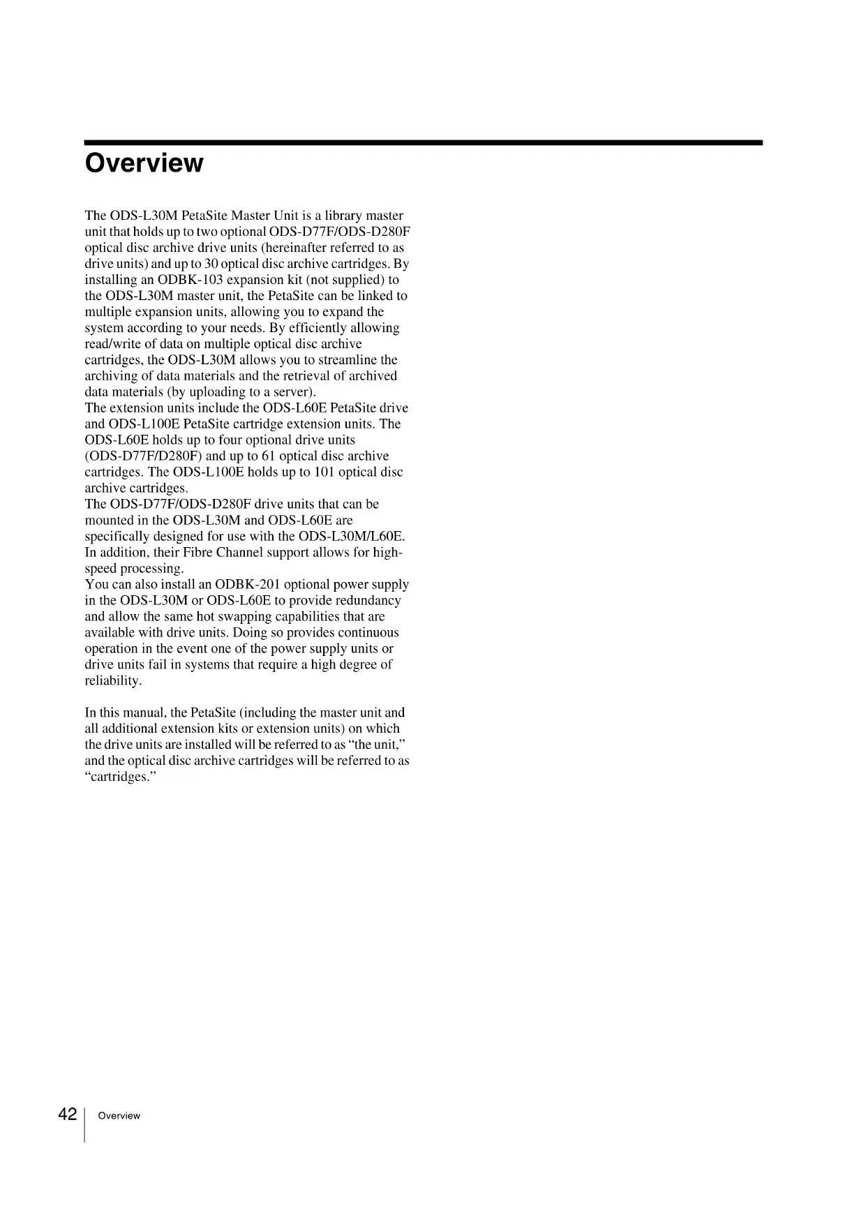
Note (ODS-D280F)
When replacing the air filter, remove the four filter lid screws that are attached to the bottom plate. Removing screws other than those specified may pose a risk of exposure to Class 3B laser radiation. For details about the air filter replacement procedure, refer to the Installation Manual supplied with the replacement air filter.
For the customers in Canada
CAN ICES-3 (A)/NMB-3(A)
WARNING
Operation of this equipment in a residential environment could cause radio interference.
For the customers in Europe
This apparatus shall not be used in the residential area.
Caution (ODS-D77F/D280F)
Use of controls or adjustments or performance of procedures other than those specified herein may result in hazardous radiation exposure.
This Optical Disc Archive Drive Unit is classified as a CLASS 1 LASER PRODUCT. (ODS-D77F/D280F)
Wavelength: 400 to 410 nm
Emission duration: Continuous
Laser output power: 280 mW (max. of pulse peak), 150 mW (max. of CW)
Standard: IEC60825-1 (2007), IEC60825-1 (2014)
Laser Diode Properties (ODS-D280F)
Wavelength: 400 to 410 nm
Emission duration: Continuous
Laser output power: 388 mW (max. of pulse peak), 150 mW (max. of CW)
Standard: IEC60825-1 (2007), IEC60825-1 (2014)
The use of optical instruments with this product will increase eye hazard.
For the customers in UAE
Caution (ODS-D77F/D280F)
This product is classified as a Class 1 Laser product under IEC60825-1:2007 (Ed2.0), IEC60825-1:2014 (Ed3.0)
(ODS-D280F)
This label is located on side surface of the product.


CE
For the customers in Europe (ODS-L30M/D77F/D280F)
Hereby, Sony Corporation, declares that ODS-L30M (PetaSite Master Unit) / ODS-D77F/D280F (Optical Disc Archive Drive Unit) is in compliance with the essential requirements and other relevant provisions of the Directive 1999/5/EC.
For details, please access the following URL : http://www.compliance.sony.de/
Pour les clients en Europe (ODS-L30M/D77F/D280F)
For the State of California, USA only
Perchlorate Material - special handling may apply, See www.dtsc.ca.gov/hazardouswaste/perchlorate
For the customers in Taiwan only

廢電池請回收
警告使用者:
For the customers in Taiwan
(ODS-L30M/ODS-L60E/ODS-D280F)
For the customers in the U.S.A.
SONY LIMITED WARRANTY - Please visit http://www.sony.com/psa/warranty for important information and complete terms and conditions of Sony's limited warranty applicable to this product.
For the customers in Canada
SONY LIMITED WARRANTY - Please visit http://www.sonybiz.ca/pro/lang/en/ca/article/resources-warranty for important information and complete terms and conditions of Sony's limited warranty applicable to this product.
For the customers in Europe
Sony Professional Solutions Europe - Standard Warranty and Exceptions on Standard Warranty. Please visit http://www.pro.sony.eu/warranty for important information and complete terms and conditions.
For the customers in Korea
SONY LIMITED WARRANTY - Please visit http://bpeng.sony.co.kr/handler/BPAS-Start for important information and complete terms and conditions of Sony's limited warranty applicable to this product.
Table of Contents
Overview 42
System Configuration Example.... 43
Name and Function of Parts.... 44
ODS-L30M.... 44
ODS-L60E.... 49
ODS-L100E.... 52
Handling Media.... 53
Media Used for Reading and Writing 53
Notes on Handling.... 53
Cartridge Memory 53
Write-Protecting Media.... 54
Barcode Labels 54
Startup and Shutdown...... 55
Startup 55
Shutdown.... 55
Importing and Exporting Cartridges.... 56
Opening the I/E Station 56
Importing and Exporting a Cartridge 56
Registration to the Database.... 56
Configuring the Network 57
Configuring the IPv4 Address.... 57
Displaying the Web Screen 59
Installing Software on Servers.... 60
Operating Environment 60
Installation 60
Menu Operation.... 61
Basic Menu Operation.... 61
Menu List 62
Messages 63
Important Notes on Operation 65
Condensation.... 65
Parts Replacement 65
LCD.... 65
Precautions for Drive Units.... 65
Replacing the air filter (ODS-D280F).... 66
Long-term loading of cartridges.... 66
Trademarks and Licenses 67
Open Software Licenses.... 67
Obtaining GPL/LGPL/GPL V3 Licensed Software.... 67
Specifications.... 67
Overview
The ODS-L30M PetaSite Master Unit is a library master unit that holds up to two optional ODS-D77F/ODS-D280F optical disc archive drive units (hereinafter referred to as drive units) and up to 30 optical disc archive cartridges. By installing an ODBK-103 expansion kit (not supplied) to the ODS-L30M master unit, the PetaSite can be linked to multiple expansion units, allowing you to expand the system according to your needs. By efficiently allowing read/write of data on multiple optical disc archive cartridges, the ODS-L30M allows you to streamline the archiving of data materials and the retrieval of archived data materials (by uploading to a server).
The extension units include the ODS-L60E PetaSite drive and ODS-L100E PetaSite cartridge extension units. The ODS-L60E holds up to four optional drive units (ODS-D77F/D280F) and up to 61 optical disc archive cartridges. The ODS-L100E holds up to 101 optical disc archive cartridges.
The ODS-D77F/ODS-D280F drive units that can be mounted in the ODS-L30M and ODS-L60E are specifically designed for use with the ODS-L30M/L60E. In addition, their Fibre Channel support allows for high-speed processing.
You can also install an ODBK-201 optional power supply in the ODS-L30M or ODS-L60E to provide redundancy and allow the same hot swapping capabilities that are available with drive units. Doing so provides continuous operation in the event one of the power supply units or drive units fail in systems that require a high degree of reliability.
In this manual, the PetaSite (including the master unit and all additional extension kits or extension units) on which the drive units are installed will be referred to as “the unit,” and the optical disc archive cartridges will be referred to as “cartridges.”
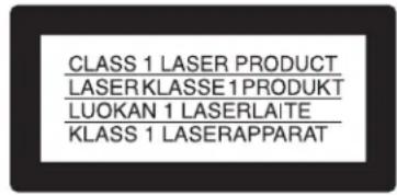
System Configuration Example
The following types of systems can be constructed using the unit in combination with related equipment.
flowchart
graph TD
    A["Macintosh computer"] --> B["Server (with HSM application)"]
    C["Windows computer"] --> B
    D["Server (with MAM application)"] --> B
    E["Gigabit ethernet switch"] --> B
    B --> F["Storage"]
    G["Ethernet"] --> H["This unit"]
    H --> I["Fibre Channel switch"]
    I --> J["Fibre Channel"]
    J --> K["Server with Ethernet"]
    style A fill:#f9f,stroke:#333
    style C fill:#f9f,stroke:#333
    style D fill:#f9f,stroke:#333
    style E fill:#ccf,stroke:#333
    style G fill:#ccf,stroke:#333
    style H fill:#cfc,stroke:#333
    style I fill:#cfc,stroke:#333
    style J fill:#cfc,stroke:#333
    style K fill:#cfc,stroke:#333
For details about the recommended server configuration for connecting a drive unit, download the technical note from the Sony Creative Software site (page 68).
Name and Function of Parts
ODS-L30M
Front panel
Note
The front panel of the ODS-L30M can be removed and interchanged with the front panels of ODS-L60E/L100E extension units. The ODS-L30M will be installed at the bottom of a stack of multiple units, but its front panel may be placed onto an extension unit whose height allows for easier operation.
① On/standby button and indicator
Switches the unit between on and standby mode when the main power switches on the rear are turned on. Press the button when it is on to switch to standby mode. A shutdown confirmation message appears on the display. Use the arrow button to select "Yes," and then press the ENTER button.
The indicator lights green when the unit is on and red when the unit is in standby mode. The indicator blinks green when the unit is shutting down.
Notes
- If the button is pressed while there is a cartridge in a drive unit, a confirmation message appears on the display. Eject the cartridge from the drive unit before proceeding.
- Exit all connected applications before shutting down the unit. Shutting down turns off the drive power supply, and any data currently being recorded will be lost.
②Display
Displays the unit's status, setting menus, messages, etc.
③ ALARM indicator
Blinks when errors or warnings occur.
Blinking red: Error
Blinking orange: Warning
④MENU button
Displays a menu in the display when pressed.
⑤Arrow buttons
Scrolls through menus in the display and sets input values.
⑥ ENTER button
Moves to the next page or confirms input values during menu operations.
⑦BACK button
Moves to the previous page or cancels input values during menu operations.
⑧I/E STATION button and indicator
Releases the I/E station's lock. The lock can be released when the indicator is lit green or orange. The indicator starts blinking orange when the lock is released. If the I/E station is not opened within ten seconds after releasing the lock, the I/E station is automatically relocked.
If the I/E station remains open for longer than three minutes, the indicator blinks red.
⑨I/E station door
Note
You can select whether the I/E station of each unit is used as an I/E slot for importing/exporting cartridges or as a storage slot (importing/exporting of cartridges is disabled). The I/E station lock cannot be released on units where the I/E station is used as a storage slot.
| Indicator Meaning | |
| Off Lock cannot be released under the following circumstances.When the I/E station is locked from an application.When the I/E station is used as a storage slot. | |
| Green (blinking) Lock cannot be released because the I/E station is currently being accessed. | |
| Green Lock can be released. There is a cartridge in the I/E station. | |
| Orange Lock can be released. There is no cartridge in the I/E station. | |
| Orange (blinking) | Lock is released. |
| Red (blinking) A problem occurred in the I/E station.One of the following messages appears on the display.CLOSE I/E STATION: I/E station was left open for over three minutes.I/E STATION LOCKED: Lock cannot be released because a button was pressed while the indicator was Off or blinking.I/E STATION OPENED: An I/E slot movement was requested while the I/E station was open.* A message does not appear on the display during menu operation. | |
I/E station labels containing the following information are supplied with the unit.
| I/E STATION indicator | Status I/E | STATION button |
| Off Opening/closing is not possible because operations are disabled. | Disabled | |
| Green (blinking) | Opening/closing is not possible because the I/E station is being accessed. | Disabled |
| Green Unlocking is possible.Green: Cartridge presentOrange: Cartridge not present | Enabled | |
| Orange (blinking) | Unlocked. Opening/closing is possible. | Disabled |
| Red (blinking) | An error has occurred.Check the unit's display. | Disabled |
Rear panel
The following illustration depicts the ODS-L30M with two ODS-D280F drive units and two power supply units installed. If ODS-D77F drive units are mounted, the rear panel structure is different. For details about the ODS-D77F, see “Rear panel (ODS-D77F)” (page 48).
①Power supply unit mount slots
Allows you to provide a redundant power supply by installing ODBK-201 optional power supplies (not supplied). Doing so provides continuous operation in the event one of the power supply units fail in systems that require a high degree of reliability.
For details on adding or replacing power supply units, consult your local Sony representative.
②Main power switches
Switch the main power supplies on or off. When using the unit, leave these switches set to on, and use the on/standby button on the front panel to switch between the operation and standby modes.
Note
When turning the main power supplies off, always set the unit to standby mode using the on/standby button on the front panel before pressing these switches.
③ AC IN connectors
Connect these to power outlets using power cords.
④Power supply unit indicators
Indicate the status of the power supply units.
Off: Normal status
Lit red: 19.5 V power supply error
⑤DC OUT connectors
Connect to the DC IN connectors of the ODS-D280F drive units to supply power to the drive units. These connectors are not used when ODS-D77F drive units are mounted.
⑥Drive unit mount slots
Allow you to install up to two optional drive units (ODS-D77F/D280F).
⑦ CARTRIDGE IN indicator
Lit green when the drive unit is turned on and a cartridge is inserted in the drive unit.
⑧ DC IN connector
Connect to the DC OUT connector of a power supply unit to supply power to the drive unit.
Note
When connecting the drive DC cable while the library power supply is turned on, use the following procedure.
- Connect the ODA control cable.
-
Connect the drive DC cable to the DC IN connector.
If the drive DC cable is connected first, the drive unit may enter "Miscommunication" state, requiring the drive unit to be restarted using the Library Maintenance Web UI.
Similarly, when removing a drive unit, use the following procedure. -
Disconnect the drive DC cable.
-
Disconnect the ODA control cable.
If the ODA control cable is disconnected first, the drive unit may turn off and then on again.
⑨FC (Fibre Channel) connectors
Allow you to connect to servers and external storage via a Fibre Channel switch.
⑩ODS CONTROL connector (ADI)
Connect to the DRIVE connector with the same number as the drive on the ODS-L30M to enable ADI (Automation/Drive Interface) control of the drive unit.
⑪Drive unit indicators
Indicate the status of the drive units. From the top, the three indicators are as follows.
- POWER indicator
Lit green: Power is being supplied.
- LINK indicator
Blinking blue slowly (once per second): FC cable is not connected.
Lit blue: FC cable is connected.
Blinking blue rapidly (four times per second): FC cable is connected and a command is being received.
Notes
- This indicator is lit blue when the FC cable is physically connected correctly. It is lit blue while the FC cable is connected, even when in states where the drive unit cannot be controlled from a computer.
- This indicator is lit blue during drive unit initialization after power is applied, even if an FC cable is not connected. In this case, the indicator starts blinking blue slowly after initialization is finished.
- STATUS indicator
Lit green: The drive unit can be replaced (i.e., drive is offline and drive power is off).
Lit red:
- An alarm occurred (alarm code other than 00-000).
- Library and drive units are not communicating normally.
- The drive unit power supply was forcibly turned off (POWER indicator also turned off) due to a library power supply fan fault.
Slow blinking green (1-sec. interval): The drive is initializing.
Rapid blinking green (0.25-sec. interval): Firmware update in progress.
Off: Normal status.
⑫OUT 2 (unit interconnection) connector
Connect to the IN 2 connector on the extension unit (ODS-L60E/L100E) using unit interconnection cable 2 (supplied with the extension unit).
⑬DRIVE 1, 2 connectors (ODS control (ADI / power supply))
Connect to the ODS CONTROL connector on the drive unit with the same number (DRIVE 1 or 2) using an ODA control cable (supplied with the drive unit) to enable ADI control. When connected with an ODS-D77F, it supplies power to the drive unit.
Note
When connecting the ODA control cable while the library power supply is turned on, use the following procedure.
- Connect the ODA control cable.
-
Connect the drive DC cable to the DC IN connector.
If the drive DC cable is connected first, the drive unit may enter “Miscommunication” state, requiring the drive unit to be restarted using the Library Maintenance Web UI.
Similarly, when removing a drive unit, use the following procedure. -
Disconnect the drive DC cable.
-
Disconnect the ODA control cable.
If the ODA control cable is disconnected first, the drive unit may turn off and then on again.
14 OUT 1 (unit interconnection) connector
Connect to the IN 1 connector on the extension unit (ODS-L60E/L100E) using unit interconnection cable 1 (supplied with the extension unit).
15 (network) port 1
Connect a network cable here to configure the unit or check its status via the Web screen.
This appears as "Network1" in the configuration screen.
16 (network) port 2 (used for maintenance)
This appears as "Network2" in the configuration screen.
CAUTION
- For safety, do not connect the connector for peripheral device wiring that might have excessive voltage to this port. Follow the instructions for this port.
- When you connect the network cable of the unit to peripheral device, use a shielded-type cable to prevent malfunction due to radiation noise.
⑰ Cable clamper
Rear panel (ODS-D77F)
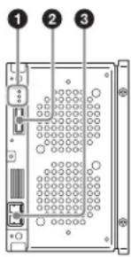
①Drive unit indicator
Indicate the status of the drive units. From the top, the three indicators are as follows.
- POWER indicator
Lit green: Power is being supplied.
- LINK indicator
Blinking blue slowly (once per second): FC cable is not connected.
Lit blue: FC cable is connected.
Blinking blue rapidly (four times per second): FC cable is connected and a command is being received.
Notes
- This indicator is lit blue when the FC cable is physically connected correctly. It is lit blue while the FC cable is connected, even when in states where the drive unit cannot be controlled from a computer.
- This indicator is lit blue during drive unit initialization after power is applied, even if an FC cable is not connected. In this case, the indicator starts blinking blue slowly after initialization is finished.
- STATUS indicator
Lit green: The drive unit can be replaced (i.e., drive is offline and drive power is off).
Lit red:
- An alarm occurred (alarm code other than 00-000).
- Library and drive units are not communicating normally.
- The drive unit power supply was forcibly turned off (POWER indicator also turned off) due to a library power supply fan fault.
Slow blinking green (1-sec. interval): The drive is initializing.
Rapid blinking green (0.25-sec. interval): Firmware update in progress.
Off: Normal status.
②ODS CONTROL connector (ADI / power supply)
Connect to the DRIVE connector with the same number as the drive on the ODS-L30M to supply power to the drive unit and to enable ADI control.
③FC (Fibre Channel) connector
Allow you to connect to servers and external storage via a Fibre Channel switch.
The following FC cables are recommended.
50-micron multi-mode optical fibre cable with LC connectors
or
62.5-micron multi-mode optical fibre cable with LC connectors
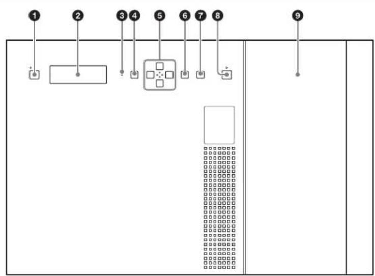
ODS-L60E
Front panel
①I/E STATION button and indicator
Releases the I/E station's lock. The lock can be released when the indicator is lit green or orange. The indicator starts blinking orange when the lock is released. If the I/E station is not opened within ten seconds after releasing the lock, the I/E station is automatically relocked. If the I/E station remains open for longer than three minutes, the indicator blinks red.
Note
You can select whether the I/E station of each unit is used as an I/E slot for importing/exporting cartridges or as a storage slot (importing/exporting of cartridges is disabled). The I/E station lock cannot be released on units where the I/E station is used as a storage slot.
| Indicator Meaning | |
| Off Lock cannot be released under the following circumstances.When the I/E station is locked from an application.When the I/E station is used as a storage slot. | |
| Green (blinking) Lock cannot be released because the I/E station is currently being accessed. | |
| Green Lock can be released. There is a cartridge in the I/E station. | |
| Orange Lock can be released. There is no cartridge in the I/E station. | |
| Indicator Meaning | |
| Orange (blinking) | Lock is released. |
| Red (blinking) A problem occurred in the I/E station.One of the following messages appears on the display.CLOSE I/E STATION: I/E station was left open for over three minutes.I/E STATION LOCKED: Lock cannot be released because a button was pressed while the indicator was Off or blinking.I/E STATION OPENED: An I/E slot movement was requested while the I/E station was open.* A message does not appear on the display during menu operation. | |
②I/E station door
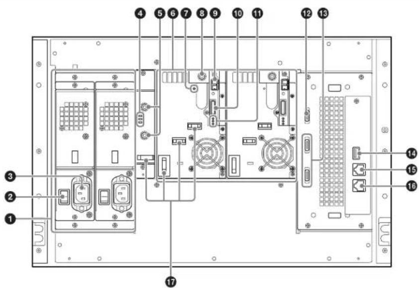
Rear panel
The following illustration depicts the ODS-L60E with four ODS-D280F drive units and two power supply units installed. If ODS-D77F drive units are mounted, the rear panel structure is different. For details about the ODS-D77F, see “Rear panel (ODS-D77F)” (page 48).
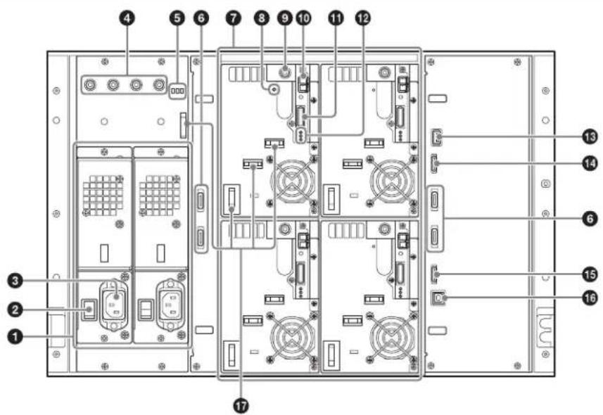
①Power supply unit mount slots
Allows you to provide a redundant power supply by installing ODBK-201 optional power supplies (not supplied). Doing so provides continuous operation in the event one of the power supply units fail in systems that require a high degree of reliability.
A power supply unit is not required if a drive unit is not installed in the ODS-L60E.
For details on adding or replacing power supply units, consult your local Sony representative.
②Main power switches
Switch the main power supplies on or off. When using the unit, leave these switches set to on, and use the on/standby button on the front panel to switch between the operation and standby modes.
Note
When turning the main power supplies off, always set the unit to standby mode using the on/standby button on the front panel of the ODS-L30M before pressing these switches.
③ AC IN connectors
Connect these to power outlets using power cords.
④DC OUT connectors
Connect to the DC IN connectors of the ODS-D280F drive units to supply power to the drive units. These connectors are not used when ODS-D77F drive units are mounted.
⑤Power supply unit indicators
Indicate the status of the power supply units.
Off: Normal status
Lit red: 19.5 V power supply error
⑥DRIVE 1 to 4 connectors (ODS control (ADI / power supply))
Connect to the ODS CONTROL connector on the drive unit with the same number (DRIVE 1 to 4) using an ODA control cable (supplied with the drive unit) to enable ADI control. When connected with an ODS-D77F, it supplies power to the drive unit.
When connecting the ODA control cable while the library power supply is turned on, use the following procedure.
-
Connect the ODA control cable.
-
Connect the drive DC cable to the DC IN connector. If the drive DC cable is connected first, the drive unit may enter "Miscommunication" state, requiring the drive unit to be restarted using the Library Maintenance Web UI. Similarly, when removing a drive unit, use the following procedure.
-
Disconnect the drive DC cable.
-
Disconnect the ODA control cable. If the ODA control cable is disconnected first, the drive unit may turn off and then on again.
⑦Drive unit mount slots
Allow you to install up to four optional drive units (ODS-D77F/D280F).
⑧ CARTRIDGE IN indicator
Lit green when the drive unit is turned on and a cartridge is inserted in the drive unit.
⑨ DC IN connector
Connect to the DC OUT connector of a power supply unit to supply power to the drive unit.
Note
When connecting the drive DC cable while the library power supply is turned on, use the following procedure.
-
Connect the ODA control cable.
-
Connect the drive DC cable to the DC IN connector. If the drive DC cable is connected first, the drive unit may enter “Miscommunication” state, requiring the drive unit to be restarted using the Library Maintenance Web UI. Similarly, when removing a drive unit, use the following procedure.
-
Disconnect the drive DC cable.
-
Disconnect the ODA control cable.
If the ODA control cable is disconnected first, the drive unit may turn off and then on again.
⑩FC (Fibre Channel) connectors
Allow you to connect to servers and external storage via a Fibre Channel switch.
⑪ ODS CONTROL connector (ADI)
Connect to the DRIVE connector with the same number as the drive on the ODS-L60E to enable ADI control.
12Drive unit indicators
Indicate the status of the drive units. From the top, the three indicators are as follows.
- POWER indicator
Lit green: Power is being supplied.
- LINK indicator
Blinking blue slowly (once per second): FC cable is not connected.
Lit blue: FC cable is connected.
Blinking blue rapidly (four times per second): FC cable is connected and a command is being received.
Notes
- This indicator is lit blue when the FC cable is physically connected correctly. It is lit blue while the FC cable is connected, even when in states where the drive unit cannot be controlled from a computer.
- This indicator is lit blue during drive unit initialization after power is applied, even if an FC cable is not connected. In this case, the indicator starts blinking blue slowly after initialization is finished.
- STATUS indicator
Lit green: The drive unit can be replaced (i.e., drive is offline and drive power is off).
Lit red:
- An alarm occurred (alarm code other than 00-000).
- Library and drive units are not communicating normally.
- The drive unit power supply was forcibly turned off (POWER indicator also turned off) due to a library power supply fan fault.
Slow blinking green (1-sec. interval): The drive is initializing.
Rapid blinking green (0.25-sec. interval): Firmware update in progress.
Off: Normal status.
13 OUT 1 (unit interconnection) connector
Connect to the IN 1 connector of the master unit (ODS-L30M) or another extension unit (ODS-L60E/L100E) using unit interconnection cable 1 (supplied with the extension unit).
14 OUT 2 (unit interconnection) connector
Connect to the IN 2 connector of the master unit (ODS-L30M) or another extension unit (ODS-L60E/L100E) using unit interconnection cable 2 (supplied with the extension unit).
⑮IN 2 (unit interconnection) connector
Connect to the OUT 2 connector of the master unit (ODS-L30M) or another extension unit (ODS-L60E/L100E) using unit interconnection cable 2 (supplied with the extension unit).
16IN 1 (unit interconnection) connector
Connect to the OUT 1 connector of the master unit (ODS-L30M) or another extension unit (ODS-L60E/L100E) using unit interconnection cable 1 (supplied with the extension unit).
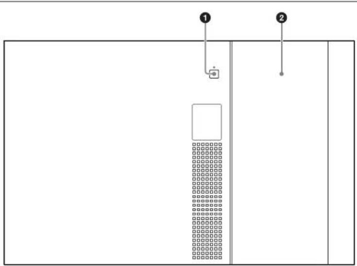
ODS-L100E
Front panel
This is identical to the front panel of the ODS-L60E (see page 49).
Rear panel
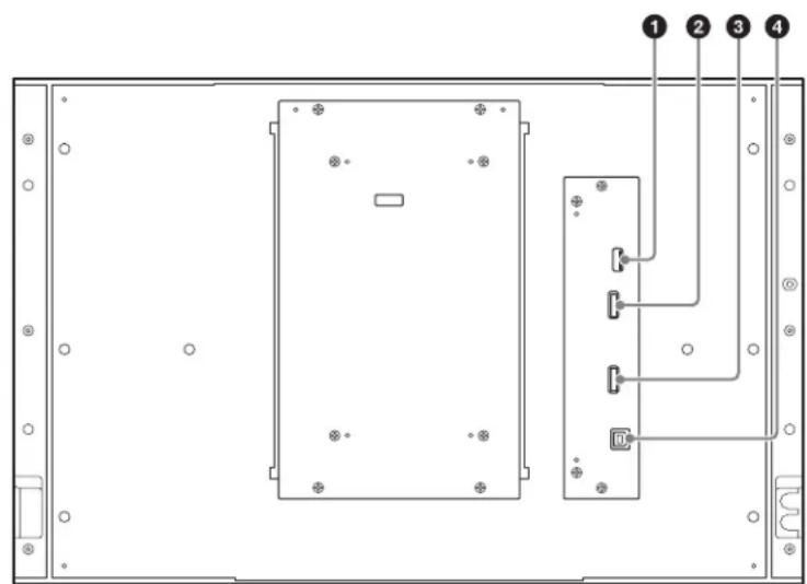
①OUT 1 (unit interconnection) connector
Connect to the IN 1 connector of the master unit (ODS-L30M) or another extension unit (ODS-L60E/L100E) using unit interconnection cable 1 (supplied with the extension unit).
②OUT 2 (unit interconnection) connector
Connect to the IN 2 connector of the master unit (ODS-L30M) or another extension unit (ODS-L60E/L100E) using unit interconnection cable 2 (supplied with the extension unit).
③IN 2 (unit interconnection) connector
Connect to the OUT 2 connector of the master unit (ODS-L30M) or another extension unit (ODS-L60E/L100E) using unit interconnection cable 2 (supplied with the extension unit).
④ OUT 1 (unit interconnection) connector
Connect to the OUT 1 connector of the master unit (ODS-L30M) or another extension unit (ODS-L60E/L100E) using unit interconnection cable 1 (supplied with the extension unit).
Handling Media
Media Used for Reading and Writing
This unit uses the following cartridges and similar media.
| Cartridge Media type | Read/write support | No. of files which can be created | ||
| ODS-D77F | ODS-D280F | |||
| ODC300RCapacity: 300 GB | Write-once | Read/Write | Not supported | 60,000 or 240,000 |
| ODC300RE Capacity: 300 GB | Rewritable | Read/Write | Not supported | 60,000 or 240,000 |
| ODC600RCapacity: 600 GB | Write-once | Read/Write | Not supported | 60,000 or 240,000 |
| ODC600RE Capacity: 600 GB | Rewritable | Read/Write | Not supported | 60,000 or 240,000 |
| ODC1200RE Capacity: 1.2 TB | Rewritable | Read/Write | Read-only | 60,000 or 240,000 |
| ODC1500RCapacity: 1.5 TB | Write-once | Read/Write | Read-only | 60,000 or 240,000 |
| ODC3300RCapacity: 3.3 TB | Write-once | Not supported | Read/Write | 480,000 |
Notes
- Deleting files from the media will not increase the available storage space for either write-once or rewritable type cartridges.
- In the case of write-once type cartridges, pay attention to the following points.
- Reformatting the media will not increase the available storage space.
- Repetitive file writing will consume the available writable space (for writing the media management data, etc.) on the media. If there is no available writable space on the media, file writing may be disabled, even if sufficient storage space remains.
- No file can be written after the media is finalized.
-
For ODC3300R cartridges, the number of files that can be created is 480,000. For cartridges other than the ODC3300R, you can select the maximum number of files that can be created (60,000 or 240,000) when you format the cartridge.
-
When you reformat write-once media, the previous maximum number of files that can be created (480,000 for ODC3300R cartridges, 60,000 or 240,000 for other cartridges) will carry over. However, you can reselect the maximum number of files that can be created when you reformat rewritable media.
- For cartridges other than the ODC3300R, if you select 240,000 as the maximum number of files that can be created during formatting, the rate of successful repair for the file repair function will be lower than when 60,000 is selected.
- Read-only cartridges cannot be formatted on the ODS-D280F.
- Do not insert ODC3300R cartridges into the ODS-D77F. Inserting a cartridge may damage the unit.
Notes on Handling
Handling
The cartridge houses multiple discs in a shell, and is designed to allow handling free of risk from dust or fingerprints. However, if the cartridge is subjected to a severe shock, for example by dropping it, this can result in damage or scratching of the discs. If a disc is scratched, it may be impossible to write data, or to read the data written on the disc. The cartridge should be handled and stored carefully.
- Do not remove any discs from the cartridge.
- Do not disassemble the cartridge.
- If the disc order in a cartridge is changed, or other discs are substituted, the cartridge will no longer be recognized by the unit and cannot be used.
- The supplied adhesive labels are recommended for indexing cartridges. Apply the label in the correct position.
Storage
- Do not store cartridges where they may be subjected to direct sunlight, or in other places where the temperature or humidity is high.
- Do not leave cartridges where dust may be able to gain ingress.
- Store cartridges in their cases.
Care of the cartridge
- Remove dust and dirt on the outside of a cartridge using a soft dry cloth.
- If condensation forms, allow ample time to dry before use.
Cartridge Memory
The cartridge includes cartridge memory, which enables contactless communication with this unit. Basic information about the cartridge is written in cartridge memory.
Using the application software will enable the user-data to be written/read in the future.
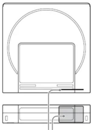
natural_image
Line drawing of a laptop connected to a device via cable (no text or symbols)Cartridge memory position
Write-Protecting Media
To prevent erasing contents of recorded media accidentally, slide the Write protect tab on the bottom of the cartridge (rear of label side) in the direction of the arrow, as shown in the following figure.
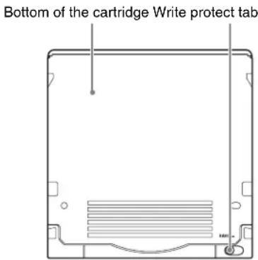
Write protect tab settings
SAVE
SAVE

Writing
enabled

Writing disabled
You can also perform the write-protect settings for media from the host application.
If either the write-protect tab or the host application is set to prohibit writing, the media will remain in the write-protected state.
Barcode Labels
The barcode reader of the unit supports CODE39 barcodes. The specifications for supported barcode labels are given below.
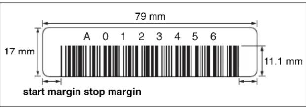
Dimensions Conformance with label frame size on the cartridges used
Label and printing
Non-glossy
Bar width Narrow bar and space width
0.423 mm (0.017 in) +0.03/-0.076 mm
(+0.001/-0.003 in) (nominal width of
0.423 mm (0.017 in))
Wide to narrow bar ratio
2.75:1
Bar length 11.1 mm (7/16 in) or more
Quiet zone (start margin/stop margin)
6.35 mm (1/4 in) or greater
Length 8 uppercase alphanumeric characters
(not including start/stop codes)
Check digit None
Notes
- Do not mark the blank spaces on either side of the barcode. The barcode may not be read properly if marks exist.
- If the label or print is glossy, proper reading may not be possible due to halation. For details on barcode labels that can be read, contact your Sony service or sales representative.
- If you want to use barcode labels with nine or more characters, contact your Sony service or sales representative.
- Attach barcode labels fully within the label area on the cartridge so that the labels do not stick out, as shown in the following diagram. Press the barcode label down firmly so that it cannot peel off.
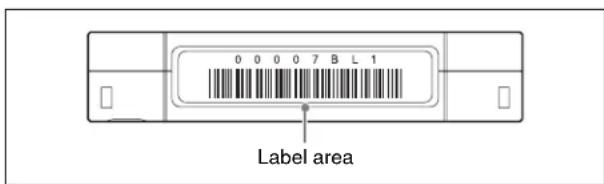
- If the label is not affixed fully within the depressed area, problems may occur with the drive unit or unit during loading.
Barcode label precautions
- Use only barcode labels that conform to Sony specifications.
- Do not affix barcode labels in which Cartridge Memory is embedded.
- Do not reuse labels or affix used labels on top of existing labels.
- Remove an old label before affixing a new one. When removing a label, peel off slowly with the label perpendicular to the attachment surface.
- Affix a new label that will not leave behind adhesive material when removed (i.e., a label that can be cleanly removed). If adhesive material remains on the cartridge, gently rub it off with your finger.
- When cleaning the label area, do not use sharp objects, water, or chemical cleaners.
- Check the state of labels before affixing them. If there are defects in the printed characters or barcode, the barcode may not be read properly, resulting in longer barcode processing times.
- When peeling labels from a label sheet, be careful not to stretch the label or cause its edges to curl.
- Be sure to affix labels flat on the cartridge without any wrinkles or air pockets.
- Be sure to affix labels fully to prevent peeling and curling.
Startup and Shutdown
Note
Always close the I/E station when starting and shutting down the unit.
Startup
1 Check that the power cord is connected, and then turn on the main power switch on the rear panel of the unit.
2 Press the on/standby button on the front panel.
When you press the button, the on/standby indicator lights green.
Initialization will end, and the unit will be ready for use when the text on the display stops blinking.
Shutdown
1 Press the on/standby button.
2 When the shutdown confirmation message appears on the display, use the arrow buttons to select [Yes], and then press the ENTER button.
Another confirmation message appears if there is a cartridge in any of the drives.
3 Wait until the on/standby indicator changes from blinking green to lit in red, and then turn off the main power switch on the rear panel.
Note
Except in an emergency, always shut down the unit before turning off the main power switch on the rear panel.
Importing and Exporting Cartridges
Opening the I/E Station
Press the I/E STATION button on the front panel to release the I/E station lock before opening the I/E station. When you press the I/E STATION button, the lock releases and the I/E STATION indicator blinks orange.
Notes
- Press and hold the I/E STATION button (for about one second) and wait until the I/E STATION indicator blinks orange before opening the I/E station.
- If the I/E station does not unlock when the I/E STATION button is pressed, push the I/E station all the way into the unit and then press the I/E STATION button again.
Importing and Exporting a Cartridge
Insert a cartridge into a slot, and push the cartridge all the way in until it stops.
When removing a cartridge, pull the cartridge out to the left while keeping it horizontal.
Closing the I/E station
Slowly push the I/E station all the way into the unit, and check that the I/E STATION indicator blinks green.
Notes
- If the I/E STATION indicator is blinking orange, the I/E station is not completely closed.
- A warning tone sounds if the I/E station is left open for 3 minutes or longer.
Registration to the Database
After inserting a cartridge and closing the I/E station, information about each cartridge is automatically registered in the unit's database. The database registration may take some time to complete when inserting multiple cartridges.
When registration to the database is complete, the I/E STATION indicator will light green or orange.
Configuring the Network
After configuring the IPv4 address in the display on the front panel of the unit, connect the unit to the computer on which the Web browser is installed, and configure the unit's settings and check its status via the Library Maintenance Web UI.
Configuring the IPv4 Address
The IP address, subnet mask, default gateway settings are required. Network 1 is configured for DHCP by factory default. Network 2 is configured with the following settings.
IP address: 192.168.1.10
Subnet mask: 255.255.255.0
Default gateway: 0.0.0.0
Use the display and the buttons on the front panel of the unit to configure the network settings.
1 Press the MENU button.
The menu appears in the display.

2 Use the ↑ and ↓ buttons to select [Setup], and press the ENTER button.
The [Setup] screen appears.
3 Use the ↑ and ↓ buttons to select [Network], and press the ENTER button.
The [Network] screen appears.
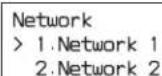
4 Use the ↑ and ↓ buttons to select [Network 1], and press the ENTER button.
The [Network1] screen appears.
Network1
1.IPv4 Setting 2.IPv6 Setting
5 Use the ↑ and ↓ buttons to select [IPv4 Setting], and press the ENTER button.
The following screen appears. An asterisk (*) indicates the current setting. To configure the IPv4 address, this setting must be set to [Enabled]. If the setting is already set to [Enabled], proceed to step 8.
IPv4 Setting IPv4 Enabled Enabled *Disabled
6 Press the ENTER button to change the setting.
The selection screen (i.e., screen with the cursor (⩾)) appears. You can change the setting in this screen.
IPv4 Setting IPv4 Enabled
Enabled *Disabled
7 Use the ↑ and ↓ buttons to select [Enabled], and press the ENTER button.
The confirmation screen (i.e., screen without the cursor (>) appears.
IPv4 Setting IPv4 Enabled *Enabled Disabled
8 Check that [Enabled] is selected, and press the ↓ button.
The following screen appears.
IPv4 Setting IPv4 DHCP Auto *Static
9 Press the ENTER button to display the selection screen.
10 To use a static IP address, use the ↑ and ↓ buttons to select [Static], and press the ENTER button.
Note
To use the DHCP, use the ↑ and ↓ buttons to select [Auto], press the ENTER button, and then proceed to step 17.
11 Press the ↓ button.
The following screen appears.
IPv4 Setting IPv4 Address 000.000.000.000
12 Press the ENTER button.
The first digit of the IP address blinks, indicating that it can be changed.
IPv4 Setting IPv4 Address 000.000.000.000
13 Enter the IP address.
Use the and buttons to move the cursor, and use the and buttons to change the values.
14 Press the ENTER button after entering the address to confirm it.
15 Press the ↓ button to display [IPv4 Netmask], and configure the subnet mask using the same method as the IP address.
IPv4 Setting IPv4 Netmask 000.000.000.000
16 Press the ↓ button to display [IPv4 Gateway], and configure the default gateway using the same method.
IPv4 Setting IPv4 Gateway 000.000.000.000
17 Press the ↓ button.
[IPv4 DNS] appears.
IPv4 Setting IPv4 DNS Auto *Static
18 To configure the DNS address, select [Static].
If the current setting is [Auto], display the selection screen using the ENTER button, use the ↑ and ↓ buttons to select [Static], and then press the ENTER button to confirm.
Note
To obtain the DNS address automatically, select [Auto]. Confirm the setting using the same method as you would with [Static], and proceed to step 24.
19 Press the ENTER button.
The [IPv4 Primary DNS] screen appears.
IPv4 Setting IPv4 Primary DNS 000.000.000.000
20 Press the ENTER button.
The first digit of the IP address blinks, indicating that it can be changed.
21 Use the , , , and buttons to enter the primary DNS address, and press the ENTER button.
22 Press the ↓ button.
The [IPv4 Secondary DNS] screen appears.
23 Enter the secondary DNS address using the same method as step 20, and press the ENTER button.
24 Press the ↓ button.
The following confirmation screen appears.
Network1 IPv4 Setting
Save Cancel
25 Check that [Save] is selected, and press the ENTER button.
The changed IP address is enabled. The [Network1] screen appears again.
Network1
1.IPv4 Setting 2.IPv6 Setting
26 Press the BACK button three times to end menu operation.
IP addresses can also be changed in the Web screen (Library Maintenance Web UI).
For details on changes using the Library Maintenance Web UI, refer to the Library Maintenance Web UI Help.
Displaying the Web Screen
A web screen (Library Maintenance Web UI) can be used to perform setting operations for this unit.
Recommended environment
Web browser:
- For Windows: Google Chrome (latest version) or Microsoft Internet Explorer 11
- For Mac OS: Google Chrome (latest version)
• Monitor size: 1,024 pixels or wider
To display the web screen, enter the URL https://(ip_address)/ into a web browser.
Example: https://192.168.1.10/
When connecting to the unit from a web browser, a “The site’s security certificate is not trusted!” or similar message appears. Check that the IP address displayed in the message is correct before proceeding.
Next, the authentication screen appears. Enter the following user name and password.
User: admin, Password: ods-130m
After authentication, the Library Maintenance Web UI screen appears.
For details on Library Maintenance Web UI operations, refer to the Library Maintenance Web UI Help.
Notes
- Consult your network administrator about the required network settings.
PCs may not connect to the unit on a network, depending on the browser proxy server settings. - Only one web client can be connected to the unit at any one time.
- The web screen supports up to three simultaneous connections (http sessions). If two or more sessions are open at the same time, an error occurs if the registration operations conflict with one another. In such cases, the operation should be issued a second time.
- The library does not perform network routing. To obtain a gateway address and an IP address automatically, configure settings for a single network only.
- Enables JavaScript in your web browser. The login screen is not displayed if JavaScript is not enabled.
- Set your web browser to accept cookies. You will not be able to log in unless you allow your browser to accept cookies from the unit.
- The web browser setup preferences vary depending on the web browser and the OS version. Refer to the operating instructions or help for your web browser and OS.
Installing Software on Servers
Install the following software on the servers that are connected via Fibre Channel to the drive units mounted in the unit. (For details on the system configuration, see page 43.)
- Optical Disc Archive Software (Windows/Linux) Basic software that connects the servers and the dive units and allows read/write of files.
Download this software from the Sony Professional products website (page 68).
Notes
- Install the software before connecting the servers to the drive units.
- Optical Disc Archive Utility will be automatically installed when you install the software.
Operating Environment
Operation of the Optical Disc Archive Software has been verified for the following environments.
Note
Operation verification does not guarantee operation on all computers.
Windows
ODS-D77F
| Item Requirement | |
| Processor Intel | Core 2 Duo 2.66 GHz or higher; or Intel Xeon 2 GHz or higher |
| Memory 2 GB | × (No. of connected devices + 1) or higher |
| HDD space 32 | GB + 16 GB × (No. of connected devices + 1) or higher |
| OS Refer to the | Sony Professional products website (page68). |
ODS-D280F
| Item Requirement | |
| Processor 3rd | Generation Intel Core i5 2.5 GHz or later,or Intel Xeon 2.27 GHz or later |
| Memory 4 GB | × (No. of connected devices + 1) or higher |
| HDD free capacity | 32 GB + 32 GB × (No. of connected devices + 1) or higher |
| Item Requirement | |
| OS Refer to the website (page68). | Sony Professional products |
Linux
ODS-D77F
| Item Requirement | |
| Processor Intel | Core 2 Duo 2.66 GHz or higher; or Intel Xeon 2 GHz or higher |
| Memory 2 GB | × (No. of connected devices + 1) or higher |
| HDD space 32 | GB + 16 GB × (No. of connected devices + 1) or higher |
| OS Refer to the website | Sony Professional products (page68). |
ODS-D280F
| Item Requirement | |
| Processor 3rd | Generation Intel Core i5 2.5 GHz or later,or Intel Xeon 2.27 GHz or later |
| Memory 4 GB | × (No. of connected devices + 1) or higher |
| HDD free capacity | 32 GB + 32 GB × (No. of connected devices + 1) or higher |
| OS Refer to the | Sony Professional products website (page68). |
Installation
Download the software from the Sony Professional products website (page 68), and install it.
Note
If the Optical Disc Archive Software is installed while certain anti-virus software, spyware tools, or products that include UDF 2.5 or 2.6 file system drivers other than those standard-equipped on the OS are also installed, operation may become unstable. If operation of the Optical Disc Archive Software becomes unstable, check for the presence of the above software and their settings, and change the settings.
Precautions for installation in Windows
- If an older version of the Optical Disc Archive Software is already installed, uninstall it before installing the new version. Remove [Sony Optical Disc Archive Software] from [Add or remove programs] in the control panel, and restart the computer.
- When you perform installation, any previously configured items will revert to initial settings.
Precautions for installation in Linux
- If you connect the drive units to the servers before installing the Optical Disc Archive Software, the operation of the servers may be disrupted. To prevent this, be sure to install the Optical Disc Archive Software before connecting the drive units to the servers. If you notice a problem with the servers, shut them down, disconnect the drive units from the servers, restart the servers, and install the Optical Disc Archive Software. Then connect the drive units to the servers.
- When you perform update install, the Optical Disc Archive Software will be overwritten. Any previously configured items will revert to default settings.
- If you install a new version of the Optical Disc Archive Software after uninstalling an older version, any previously configured items will revert to default settings.
Menu Operation
Configure basic settings of the unit and display the unit's status using the menu displayed on the front panel of the unit. Use the buttons on the front panel to operate the menu.
Basic Menu Operation
This section describes basic menu operations, using the warning tone setting as an example.
1 Press the MENU button.
The menu selection screen appears.
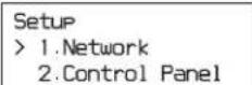
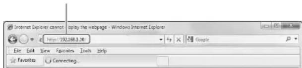
2 Move the cursor (>) using the ↑ and ↓ buttons and select [Setup], and then press the ENTER button.
The submenu of the selected item appears.
![SONY ODS-L60E - Move the cursor (>) using the ↑ and ↓ buttons and select [Setup], and then press the ENTER button. - 1](/content/2026/04/637676/images/89290e8246bfa94d96d13428899431ce2ad2e5e0dc664365696f676f1d6cc974.jpg)
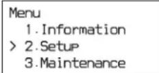
3 Use the ↑ and ↓ buttons to select [Control Panel], and press the ENTER button.
The submenu of the selected item appears.
![SONY ODS-L60E - Use the ↑ and ↓ buttons to select [Control Panel], and press the ENTER button. - 1](/content/2026/04/637676/images/460f16be984c14b2be1d68c50136228ba4144f269c944ccb97ef0bede40661da.jpg)
4 Use the ↑ and ↓ buttons to select [Buzzer], and press the ENTER button.
The current setting of the selected item appears. The asterisk (*) indicates the current setting.
![SONY ODS-L60E - Use the ↑ and ↓ buttons to select [Buzzer], and press the ENTER button. - 1](/content/2026/04/637676/images/67c97b35d27db90b4d625adbbaaafd22d695f48a56a8eb3596c17fb8ef690136.jpg)
5 Press the ENTER button.
The cursor (>) appears, indicating that the setting can be changed.
| Control Panel |
| Buzzer |
| ON |
| >OFF |
6 Use the ↑ and ↓ buttons to move the cursor (>).
Control Panel
| Control Panel Buzzer |
| >ON |
| *OFF |
7 Press the ENTER button to confirm the setting.
The cursor disappears, and the setting is confirmed.
| Control Panel |
| Buzzer |
| *ON |
| OFF |
8 Press the MENU button to return to the menu selection screen (step 1).
Pressing the BACK button returns to the immediately preceding screen.
9 Press the MENU button again to end menu operation.
Menu List
| Menu Description | |
| Information Displays the | current values of each setting in the [Setup] menu and the following IPv6 parameters.IPv6 Temporary: Displays the IPv6 temporary address.IPv6 Link-Local: Displays the IPv6 link-local address. |
| Setup Allows you to config | Figure the unit's settings. |
| Menu Description | |
| 1.Network Configures the network settings. Network 1 / Network 2: Configures settings for the ODS-L30M's two network ports. IPv4 Enabled / IPv6 Enabled: Enables or disables IPv4 or IPv6. IPv4 DHCP / IPv6 DHCP: Specifies whether to use the DHCP for the IPv4 or IPv6 IP address or whether to use a static address. IPv4 Address / IPv6 Address: Configures the IPv4 or IPv6 IP address. IPv4 Netmask: Configures the IPv4 subnet mask. IPv6 Subnetprefix: Configures the IPv6 subnet prefix. IPv4 Gateway / IPv6 Gateway: Configures the IPv4 and IPv6 default gateway. IPv4 DNS / IPv6 DNS: Specifies whether to obtain the IPv4 or IPv6 IP DNS automatically or whether to use a static address. IPv4 Primary DNS / IPv6 Primary DNS: Configures the IPv4 and IPv6 primary DNS. IPv4 Secondary DNS / IPv6 Secondary DNS: Configures the IPv4 and IPv6 secondary DNS. | |
| 2.Control Panel Configures the control panel settings. Buzzer: Turns the warning tone on or off. LCD Backlight: Specifies whether the LCD backlight turns off automatically or whether it is always on. LCD Brightness: Sets the LCD brightness to Low, Middle, or High. | |
| Maintenance Menu used for maintenance. | |
| 1.Configuration Factory Setting: Restores the unit's configurations to their factory default settings. | |
| 2.Diagnostic Menu for service personnel. | |
| 3.Power Management Reboot: Restarts the unit. | |
| 4.Service Menu for service personnel. | |
Messages
If there is a problem with the unit's hardware or configuration settings, the ALARM indicator on the front panel of the unit flashes red (error) or orange (warning) and a message appears on the display. Messages are not displayed during menu operation. Messages are displayed after pressing the BACK button to exit the menu.
If a message appears, refer to the following to resolve the issue. If the message display persists, consult your local Sony representative.
| Message Description | |
| ERROR POWER OFF REQUEST | A system reboot is required. Turn the unit off, and then turn it on again. |
| ERROR BOOT OS | An error occurred during booting.Consult your local Sony representative. |
| ERROR CALIBRATION | An error occurred during carrier calibration.Consult your local Sony representative. |
| ERROR FIRMWARE UPDATE REQUEST | A firmware update is required.Consult your local Sony representative. |
| ERROR SERVICE MAINTENANCE REQUEST | Check that the unit interconnection cable is connected correctly. If there is no problem with the cable connection, maintenance by service personnel is required.Consult your local Sony representative. |
| ERROR An error was detected during control operations.Check [Library Status] on the [System] tab of the Library Maintenance Web UI. | |
| WARNING UNIT (1~6) POWER (A/B) : OFF | A power supply unit, which is configured for monitoring in the power configuration settings, is turned off.Check [Power Configuration Settings] on the [Others] tab of the [Configuration] screen of the Library Maintenance Web UI. If there is no problem with the settings, consult your local Sony representative. |
| WARNING UNIT (1~6) POWER (A/B) : NG | An error was detected with the fan of the power supply. Check the area surrounding the corresponding fan for blockages and check for any matter adhering to the fan.If there is no blockage or matter adhering to the fan, consult your local Sony representative. |
| WARNING UNIT (1~6) POWER (A/B) : CC | The power supply unit is turned on, but it is not configured for monitoring in the power configuration settings.Place a check mark in the checkboxes for the power supplies to use in [Power Configuration Settings] on the [Others] tab of the [Configuration] screen of the Library Maintenance Web UI. |
| WARNING UNIT (2~6) FAN (1~4) : NG | An error was detected with a fan in the ODS-L60E.Consult your local Sony representative. |
| WARNING HIGH TEMP | The unit's internal temperature is too high. The unit will continue to operate, but extended use will cause the unit and drive unit internal temperature to increase further, risking failure or even fire.Consult your local Sony representative. |
| WARNING FAN | The rotation speed of the fan has dropped. The unit will continue to operate, but extended use will cause the unit and drive unit internal temperature to increase further, risking failure or even fire.Consult your local Sony representative. |
| WARNING SSD | The SSD diagnosis has determined that replacement is necessary.Consult your local Sony representative. |
| WARNING LITHIUM BATTERY | Replacement of the lithium battery is necessary.Consult your local Sony representative. |
| CLOSE I/E STATION | The I/E station has been open for 3 minutes. Make sure the I/E station is fully closed.If the message appears even after closing the I/E station, consult your local Sony representative. |
| I/E STATION LOCKED | The I/E station button was pressed while the I/E station was locked by an application or the I/E station was configured for use as a storage slot.Release the lock via the application, and then press the I/E STATION button. If the lock cannot be released via the application, release the lock using the Library Maintenance Web UI. |
| I/E STATIONBUSY | The I/E STATION button was pressed while the I/E station was being accessed.Wait for the I/E STATION indicator to light green or orange before pressing the I/E STATION button. |
| I/E STATIONNOT UNLOCKED | Unlocking of the I/E station failed.Press the I/E station all the way into the unit so that it is fully inserted, and then try pressing the I/ESTATION button again. |
| I/E STATION HALF-CLOSED | The I/E station is not fully inserted.Press the I/E station all the way into the unit so that it is fully inserted, and then try pressing the I/ESTATION button again. |
| PUSH I/E STATION The I/E | E station has been in a state of incomplete insertion for at least 15 seconds.Press the I/E station all the way into the unit so that it is fully inserted. |
| REMOVE CARTRIDGEFROM CARRIER | Import processing for the I/E station cannot be performed due to the presence of a cartridge in the carrier.Move the cartridge from the carrier to an empty slot via the [Move Cartridge] tab of the Library Maintenance Web UI. |
| ERROR CALIBRATIONREMOVE CARTRIDGEFROM CARRIER | Carrier adjustment failed due to the presence of a cartridge in the carrier. Consult your local Sony representative. |
| I/E STATIONOPENED | An I/E slot movement prompt was issued while the I/E station was open.Close the I/E station, or check the application controls. |
| UNIT CONFIG CHANGEREQUEST | A change in the unit configuration was detected.Consult your local Sony representative. |
| DIAGNOSTIC LIBRARYREQUEST | Library diagnostics are required.Consult your local Sony representative. |
| EXPORTED CARTRIDGEIN I/E STATIONUNIT | A cartridge was exported to the I/E station of the displayed unit. Remove the cartridge from the I/E station as required. |
| I/E STATION UNLOCKEDUNIT | The I/E station of the displayed unit is unlocked. Open the I/E station, exchange the cartridge, and then close the I/E station. |
| BULK IMPORT MODE [Bulk Import] is set to “ON” on the [Import/Export Cartridge] tab of the Library Maintenance Web UI.After cartridge import processing is finished, always set [Bulk Import] to “OFF.” | |
Important Notes on Operation
Use and storage
Do not subject the unit to severe shocks
The internal mechanism may be damaged or the body warped.
Do not cover the unit while operating
Doing so will cause temperatures to rise inside the unit, possibly resulting in failure.
After use
Turn off the on/standby button.
If you plan not to use the unit for a long time, turn off the main power switch on the rear panel as well.
Shipping
• Always power the unit off.
- If sending the unit by truck, ship, air or other transportation service, pack it in the shipping carton of the unit.
- If the unit is shipped without being properly packed and protected. Its Internal parts may be damaged.
Referring to the Installation Manual, be sure to mount the screws and fittings to ensure safe transportation.
- If the unit is transported with the drive unit not removed, the unit and the drive unit may be damaged during transportation. Be sure to remove the drive unit from this unit before proceeding to transportation.
Care of the unit
If the body of the unit is dirty, clean it with a soft, dry cloth. In extreme cases, use a cloth steeped in a little neutral detergent, then wipe dry. Do not use organic solvents such as alcohol or thinners, as these may cause discoloration or other damage to the finish of the unit.
In the event of operating problems
If you should experience problems with the unit, contact your Sony service or sales representative.
Use and storage locations
Store in a level, ventilated place. Avoid using or storing the unit in the following places.
- In excessive heat or cold (operating temperature range: 5^ to 35^ ( 41^ to 95^ ))
Remember that in summer or in warm climates the temperature inside a car with the windows closed can easily exceed 50 °C ( 122 °F ).
• In damp or dusty locations - Locations where the unit may be exposed to rain
-
Locations subject to violent vibration
• Near strong magnetic fields -
Close to radio or TV transmitters producing strong electromagnetic fields.
- In direct sunlight or close to heaters for extended periods
To prevent electromagnetic interference from portable communications devices
The use of portable telephones and other communications devices near this unit can result in malfunctions.
It is recommended that the portable communications devices near this unit be powered off.
Condensation
If the unit is suddenly taken from a cold to a warm location, or if ambient temperature suddenly rises, moisture may form on the outer surface of the unit and/or inside of the unit. This is known as condensation. If condensation occurs, turn off the unit and wait until the condensation clears before operating the unit. Operating the unit while condensation is present may damage the unit.
Parts Replacement
The carrier (transport mechanism) is a consumable part that will need periodic replacement.
When operating at room temperature, a normal replacement cycle will be about every five years.
However, this replacement cycle represents only a general guideline and does not imply that the life expectancy of these parts is guaranteed. For details on parts replacement, contact your dealer.
LCD
Over a long period of use, because of the physical characteristics of the liquid crystal display, “stuck” pixels may appear spontaneously. These problems are not a malfunction.
Precautions for Drive Units
Shocks and vibrations
Do not subject the drive units to excessive shock or vibration, as doing so may result in damage to the drive units. If a cartridge is inserted in a drive unit while it is subjected to shock or vibration, the disc may also be damaged.
Shipping and transportation of the drive unit
If the drive unit is shipped or transported with the cartridges inserted, the drive unit or the disc may become damaged. Always remove the cartridges when shipping or transporting the drive unit.
Do not lift the drive unit with your hand inside in the cartridge insertion slot. Doing so may deform the lid, and adversely affect function and performance.
File read time
- When accessing multiple files at the same time, disc swapping may occur frequently. This will reduce the data transfer rate and increase the total time of operation significantly.
- When accessing a single file, disc swapping may also occur, depending on the recording position in the cartridge. This will take time before starting to read the file.
File write time
When writing a large number of small-sized files (e.g., 100 MB or smaller) consecutively, writing may take some time to complete. In such cases, setting the operation mode to “Synchronize management data to the media immediately after completion of file writing: Off” increases the write performance and media efficiency. However, if a malfunction (e.g., power supply failure) occurs during a write operation, the possibility of file recovery is lowered.
Replacing the air filter (ODS-D280F)
If the air filter replacement alarm (3F-511) occurs while using the ODS-D280F, replace the air filter immediately.
Note
Continued use in this state may cause read/write errors and may lead to failure.
The air filter replacement schedule will vary with the usage environment.
Before replacing the air filter, always eject all cartridges from the unit and power off the unit.
For details about the air filter replacement procedure and actions after replacement, refer to the Installation Manual supplied with the replacement air filter.
For details about obtaining an air filter and air filter replacement, consult your local Sony service or sales representative. (Parts available from July, 2017)
Long-term loading of cartridges
Eject the cartridges from the drive unit if the drive unit will be connected to a server for lengthy intervals without reading or writing data. The drive unit may be accessed, depending on the software installed on the server, even if you do not intentionally read or write. This may lead to early replacement of the optical head or may adversely affect the media.
Trademarks and Licenses
Open Software Licenses
On the basis of license contracts between Sony and the software copyright holders, this product uses open software.
To meet the requirements of the software copyright holders, Sony is obligated to inform you of the content of these licenses.
For the content of these licenses, see “Open Source Software License List” in the software Help.
Obtaining GPL/LGPL/GPL V3 Licensed Software
This product uses software licensed under GPL version 2 / LGPL version 2.1 / GPL version 3. You have the right to obtain, change, and distribute the source code of this software.
You can download the source code of this software from Sony Internet servers. For more information about how to download it, access the following URL. http://oss.sony.net/Products/Linux/common/search.html
We cannot respond to inquiries regarding the content of the source code.
Specifications
ODS-L30M specifications shown. For ODS-L60E, ODS-L100E, ODBK-201, ODBK-103, ODS-D77F, and ODS-D280F specifications, refer to the Operation Guide for each device.
General
Power requirements
$$ 1 0 0 \mathrm{V} \text { to } 2 4 0 \mathrm{V} \mathrm{AC}, 5 0 \mathrm{Hz} / 6 0 \mathrm{Hz} $$
Current consumption
$$ 1. 6 \mathrm{A} \text { to } 3. 7 \mathrm{A} $$
Operating temperature
$$ 5 ^ {\circ} \mathrm{C} \text {to} 3 5 ^ {\circ} \mathrm{C} (4 1 ^ {\circ} \mathrm{F} \text {to} 9 5 ^ {\circ} \mathrm{F}) $$
Storage temperature
$$ - 2 0 ^ {\circ} \mathrm{C} \text {to} + 5 5 ^ {\circ} \mathrm{C} (- 4 ^ {\circ} \mathrm{F} \text {to} + 1 3 1 ^ {\circ} \mathrm{F}) $$
Operating humidity
$$ 20 \% \text{ to } 80 \% \text{(relative humidity)} $$
Storage humidity
$$ \text{Less than} 75 \% $$
Mass 31 kg (68 lb. 5.5 oz.)
(excluding drive units and cartridges)
Dimensions (W × H × D)
$$ 4 4 5 \times 3 0 8 \times 9 9 2 \mathrm{mm} \left(1 7 ^ {5} / _ {8} \times 1 2 ^ {1} / _ {4} \times \right. $$
$$ 3 9 ^ {1 / _ {8}} \text { inches) (excluding protrusions) } $$
Input/output

(Network) RJ-45 type modular jack (2)
1000BASE-T: IEEE 802.3ab standard
100BASE-Tx: IEEE 802.3u standard
Accessories
Operation manual (1)
Rack mount kit (1 set)
Rack mount plate washers (4)
Screws (B4 × 10) (8)
Screws (B5 × 16) (8)
Mounting brackets (2)
Thickness gauge 025 (3)
Thickness gauge 050 (3)
Thickness gauge 100 (3)
Height support 025 (3)
Height support 050 (3)
Height support 100 (3)
Height support M 025 (1)
Height support M 050 (1)
Height support M 100 (1)
I/E station labels (1 set)
Options
ODBK-201 Power Supply
ODBK-103 Extension Kit
Option for the ODS-L30M (not compatible with models with serial numbers 10001 to 10999 and 50001 to 50999)
The serial number of the ODS-L30M can be found on the nameplate on the rear panel.
Optical Disc Archive Cartridge
• ODC300R (300 GB, write-once type)
• ODC300RE (300 GB, rewritable type)
• ODC600R (600 GB, write-once type)
• ODC600RE (600 GB, rewritable type)
- ODC1200RE (1.2 TB, rewritable type)
• ODC1500R (1.5 TB, write-once type)
• ODC3300R (3.3 TB, write-once type)
Design and specifications are subject to change without notice.
Notes
• Always verify that the unit is operating properly before use. SONY WILL NOT BE LIABLE FOR DAMAGES OF ANY KIND INCLUDING, BUT NOT LIMITED TO, COMPENSATION OR REIMBURSEMENT ON ACCOUNT OF THE LOSS OF PRESENT OR PROSPECTIVE PROFITS DUE TO FAILURE OF THIS UNIT, EITHER DURING THE WARRANTY PERIOD OR AFTER EXPIRATION OF THE WARRANTY, OR FOR ANY OTHER REASON WHATSOEVER.
- SONY WILL NOT BE LIABLE FOR CLAIMS OF ANY KIND MADE BY USERS OF THIS UNIT OR MADE BY THIRD PARTIES.
- SONY WILL NOT BE LIABLE FOR THE TERMINATION OR DISCONTINUATION OF ANY SERVICES RELATED TO THIS UNIT THAT MAY RESULT DUE TO CIRCUMSTANCES OF ANY KIND.
SONY WILL NOT BE LIABLE FOR DAMAGES OF ANY KIND RESULTING FROM A FAILURE TO IMPLEMENT PROPER SECURITY MEASURES ON TRANSMISSION DEVICES, UNAVOIDABLE DATA LEAKS RESULTING FROM TRANSMISSION SPECIFICATIONS, OR SECURITY PROBLEMS OF ANY KIND.
Depending on the operating environment, unauthorized third parties on the network may be able to access the unit. When connecting the unit to the network, be sure to confirm that the network is protected securely.
From a safety standpoint, when using the unit connected with the network, it is strongly recommended to access the Control window via a Web browser and change the access limitation settings from the factory preset values (Refer to the Others tab of the Configuration screen on the Library Maintenance Web UI Help.). Changing the password regularly is also recommended.
Software Downloads
When the unit is used with a PC connection, download any device drivers, plug-ins, and application software you require from the following websites.
Sony Creative Software, software download page: http://www.sonycreativesoftware.com/download/software_for_sony_equipment
Sony Professional products website: U.S.A. http://pro.sony.com Canada http://www.sonybiz.ca Latin America http://sonypro-latin.com Europe http://www.pro.sony.eu/pro Middle East, Africa http://sony-psmea.com Russia http://sony.ru/pro/ Brazil http://sonypro.com.br Australia http://pro.sony.com.au New Zealand http://pro.sony.co.nz Japan http://www.sonybsc.com Asia Pacific http://pro.sony-asia.com Korea http://bp.sony.co.kr
China http://pro.sony.com.cn India http://pro.sony.co.in
Français
Remarque
natural_image
Line drawing of a laptop connected to a device via cable (no text or symbols)
- Network
- Control Panel
| Control Panel |
| Buzzer |
| *ON |
| OFF |
Dimensions (L × H × P)
$$ \begin{array}{c} 4 4 5 \times 3 0 8 \times 9 9 2 \mathrm{mm} (1 7 ^ {5} / _ {8} \times 1 2 ^ {1} / _ {4} \times \ 3 9 ^ {1} / _ {8} \text { pouces) } (\text { sans les protubérances }) \end{array} $$
Entrée/sortie
http://www.sonycreativesoftware.com/download/software_for_sony_equipment
Hinweis
①Taste und LED I/E STATION
natural_image
Line drawing of a laptop connected to a device via cable (no text or symbols)1.Network
2. Control Panel
Control Panel
> 1.Buzzer
2.LCD Backlight
3.LCD Brightness
Control Panel
Buzzer
ON
*OFF
Control Panel
Buzzer
*ON
OFF
Sony Creative Software, Software- Downloadseite: http://www.sonycreativesoftware.com/download/software_for_sony_equipment
Nota
①Pulsante e indicatore I/E STATION
natural_image
Line drawing of a laptop connected to a device via cable (no text or symbols)natural_image
Technical line drawing of a rectangular electronic device with internal components and mounting holes (no text or symbols)| Control Panel |
| Buzzer |
| *ON |
| OFF |
Licenze Open Source Software
Dimensioni (L × A × P)
Software Sony Creative, pagina di download del software: http://www.sonycreativesoftware.com/download/software_for_sony_equipment
Nota
⑩Conector ODS CONTROL (ADI)
natural_image
Line drawing of a laptop connected to a device via cable (no text or symbols)natural_image
Technical line drawing of a rectangular electronic device with internal circuit lines and mounting holes (no text or symbols)Control Panel
> 1.Buzzer
2.LCD Backlight
3.LCD Brightness
Control Panel
Buzzer
ON
*OFF
Control Panel
Buzzer
*ON
OFF
注意
①电源设备安装插槽
①I/E STATION 键和指示灯
①电源设备安装插槽
①OUT 1(单元互连)接口
Control Panel
> 1.Buzzer
2.LCD Backlight
3.LCD Brightness
Control Panel
Buzzer
ON
*OFF
5 按下 ENTER 键。
出现光标(>),表示可以更改设置。
Control Panel
Buzzer
ON
>*OFF
Control Panel
Buzzer
*ON
OFF
Sony Creative Software 软件下载页面:http://www.sonycreativesoftware.com/download/software_for_sony_equipment
natural_image
Technical line drawing of a computer chassis with internal components and connectors (no text or symbols)ECKEPTY: (ODS-L30M/L60E)
ECKEPTY (ODS-L30M/L60E)
Copyright (C) 2000-2003 by Embedded and Real-Time Systems Laboratory Toyohashi Univ. of Technology, JAPAN
Copyright (C) 2004-2011 by Embedded and Real-Time Systems Laboratory Graduate School of Information Science, Nagoya Univ., JAPAN
Copyright (C) 2007-2008 by TAKAGI Nobuhisa
Copyright (C) 2004 by Atmark Techno, Inc.
The above copyright holders grant permission gratis to use, duplicate, modify, or redistribute (hereafter called use) this software (including the one made by modifying this software), provided that the following four conditions (1) through (4) are satisfied.
(1) When this software is used in the form of source code, the above copyright notice, this use conditions, and the disclaimer shown below must be retained in the source code without modification.
(2) When this software is redistributed in the forms usable for the development of other software, such as in library form, the above copyright notice, this use conditions, and the disclaimer shown below must be shown without modification in the document provided with the redistributed software, such as the user manual.
(3) When this software is redistributed in the forms unusable for the development of other software, such as the case when the software is embedded in a piece of equipment, either of the following two conditions must be satisfied:
(a) The above copyright notice, this use conditions, and the disclaimer shown below must be shown without modification in the document provided with the redistributed software, such as the user manual.
(b) How the software is to be redistributed must be reported to the TOPPERS Project according to the procedure described separately.
(4) The above copyright holders and the TOPPERS Project are exempt from responsibility for any type of damage directly or indirectly caused from the use of this software and are indemnified by any users or end users of this software from any and all causes of action whatsoever.
THIS SOFTWARE IS PROVIDED "AS IS." THE ABOVE COPYRIGHT HOLDERS AND THE TOPPERS PROJECT DISCLAIM ANY EXPRESS OR IMPLIED WARRANTIES, INCLUDING, BUT NOT LIMITED TO, ITS APPLICABILITY TO A PARTICULAR PURPOSE. IN NO EVENT SHALL THE ABOVE COPYRIGHT HOLDERS AND THE TOPPERS PROJECT BE LIABLE FOR ANY TYPE OF DAMAGE DIRECTLY OR INDIRECTLY CAUSED FROM THE USE OF THIS SOFTWARE.
ncurses-5.9-r9.1 copyright notice
The MIT License (MIT)
Copyright (c) 1998-2004,2006 Free Software Foundation, Inc.
Permission is hereby granted, free of charge, to any person obtaining a copy of this software and associated documentation files (the "Software"), to deal in the Software without restriction, including without limitation the rights to use, copy, modify, merge, publish, distribute, sublicense, and/or sell copies of the Software, and to permit persons to whom the Software is furnished to do so, subject to the following conditions:
The above copyright notice and this permission notice shall be included in all copies or substantial portions of the Software.
THE SOFTWARE IS PROVIDED "AS IS", WITHOUT WARRANTY OF ANY KIND, EXPRESS OR IMPLIED, INCLUDING BUT NOT LIMITED TO THE WARRANTIES OF MERCHANTABILITY, FITNESS FOR A PARTICULAR PURPOSE AND NONINFRINGEMENT. IN NO EVENT SHALL THE AUTHORS OR COPYRIGHT HOLDERS BE LIABLE FOR ANY CLAIM, DAMAGES OR OTHER LIABILITY, WHETHER IN AN ACTION OF CONTRACT, TORT OR OTHERWISE, ARISING FROM, OUT OF OR IN CONNECTION WITH THE SOFTWARE OR THE USE OR OTHER DEALINGS IN THE SOFTWARE.
Except as contained in this notice, the name(s) of the above copyright holders shall not be used in advertising or otherwise to promote the sale, use or other dealings in this Software without prior written authorization.
The material contained in this manual consists of information that is the property of Sony Corporation and is intended solely for use by the purchasers of the equipment described in this manual.
Sony Corporation expressly prohibits the duplication of any portion of this manual or the use thereof for any purpose other than the operation or maintenance of the equipment described in this manual without the express written permission of Sony Corporation.
- Microsoft, Windows and Internet Explorer are registered trademarks of Microsoft Corporation in the United States and other countries.
• Mac OS and Safari are trademarks or registered trademarks of Apple, Inc. - Google Chrome is a trademark or registered trademark of Google Inc.
Marques commerciales

- 安全のために
- ご注意
- ①電源ユニット装着部
- ①OUT 1(ユニット間接続)端子
- WARNING
- THIS APPARATUS MUST BE EARTHED. (ODS-L30M/L60E)
- Attention-when the product is installed in Rack (ODS-L30M/L60E/L100E):
- Prevention against overloading of branch circuit
- Providing protective earth
- Internal air ambient temperature of the rack
- Prevention against achieving hazardous condition due to uneven mechanical loading
- Install the equipment while taking the operating temperature of the equipment into consideration
- When performing the installation, keep the
- WARNING (ODS-L30M/L60E): THIS WARNING IS APPLICABLE FOR USA ONLY.
- WARNING (ODS-L30M/L60E): THIS WARNING IS APPLICABLE FOR OTHER COUNTRIES.
- IMPORTANT (ODS-L30M/L60E/L100E/D280F)
- IMPORTANT (ODS-D77F)
- For kundene i Norge (ODS-L30M/L60E)
- For the customers in the U.S.A.
- (ODS-D280F)
- Note (ODS-D280F)
- For the customers in Canada
- For the customers in Europe
- Caution (ODS-D77F/D280F)
- Laser Diode Properties (ODS-D280F)
- For the customers in UAE
- CE
- For the customers in Europe (ODS-L30M/D77F/D280F)
- Pour les clients en Europe (ODS-L30M/D77F/D280F)
- For the State of California, USA only
- For the customers in Taiwan only
- 警告使用者:
- For the customers in Taiwan
- (ODS-L30M/ODS-L60E/ODS-D280F)
- For the customers in Korea
- Table of Contents
- Overview 42
- Name and Function of Parts.... 44
- Handling Media.... 53
- Startup and Shutdown...... 55
- Importing and Exporting Cartridges.... 56
- Configuring the Network 57
- Installing Software on Servers.... 60
- Menu Operation.... 61
- Messages 63
- Important Notes on Operation 65
- Trademarks and Licenses 67
- Specifications.... 67
- Overview
- System Configuration Example
- Name and Function of Parts
- ODS-L30M
- Front panel
- Note
- ① On/standby button and indicator
- Notes
- ②Display
- ③ ALARM indicator
- ④MENU button
- ⑤Arrow buttons
- ⑥ ENTER button
- ⑦BACK button
- ⑧I/E STATION button and indicator
- Rear panel
- ①Power supply unit mount slots
- ②Main power switches
- ③ AC IN connectors
- ④Power supply unit indicators
- ⑤DC OUT connectors
- ⑥Drive unit mount slots
- ⑦ CARTRIDGE IN indicator
- ⑧ DC IN connector
- ⑨FC (Fibre Channel) connectors
- ⑩ODS CONTROL connector (ADI)
- ⑪Drive unit indicators
- - POWER indicator
- - LINK indicator
- - STATUS indicator
- ⑫OUT 2 (unit interconnection) connector
- ⑬DRIVE 1, 2 connectors (ODS control (ADI / power supply))
- OUT 1 (unit interconnection) connector
- (network) port 1
- (network) port 2 (used for maintenance)
- CAUTION
- ⑰ Cable clamper
- Rear panel (ODS-D77F)
- ①Drive unit indicator
- ②ODS CONTROL connector (ADI / power supply)
- ③FC (Fibre Channel) connector
- ODS-L60E
- ①I/E STATION button and indicator
- ②I/E station door
- ④DC OUT connectors
- ⑤Power supply unit indicators
- ⑥DRIVE 1 to 4 connectors (ODS control (ADI / power supply))
- ⑦Drive unit mount slots
- ⑧ CARTRIDGE IN indicator
- ⑨ DC IN connector
- ⑩FC (Fibre Channel) connectors
- ⑪ ODS CONTROL connector (ADI)
- 12Drive unit indicators
- OUT 1 (unit interconnection) connector
- OUT 2 (unit interconnection) connector
- ⑮IN 2 (unit interconnection) connector
- 16IN 1 (unit interconnection) connector
- ODS-L100E
- ①OUT 1 (unit interconnection) connector
- ②OUT 2 (unit interconnection) connector
- ③IN 2 (unit interconnection) connector
- ④ OUT 1 (unit interconnection) connector
- Handling Media
- Media Used for Reading and Writing
- Notes on Handling
- Handling
- Storage
- Care of the cartridge
- Cartridge Memory
- Write-Protecting Media
- Barcode Labels
- Barcode label precautions
- Startup and Shutdown
- Startup
- Shutdown
- Importing and Exporting Cartridges
- Opening the I/E Station
- Importing and Exporting a Cartridge
- Closing the I/E station
- Registration to the Database
- Configuring the Network
- Configuring the IPv4 Address
- Displaying the Web Screen
- Recommended environment
- Installing Software on Servers
- Operating Environment
- Windows
- Linux
- Installation
- Precautions for installation in Windows
- Precautions for installation in Linux
- Menu Operation
- Basic Menu Operation
- Press the MENU button.
- Move the cursor (>) using the ↑ and ↓ buttons and select [Setup], and then press the ENTER button.
- Use the ↑ and ↓ buttons to select [Control Panel], and press the ENTER button.
- Use the ↑ and ↓ buttons to select [Buzzer], and press the ENTER button.
- Press the ENTER button.
- Messages
- Important Notes on Operation
- Use and storage
- Do not subject the unit to severe shocks
- Do not cover the unit while operating
- After use
- Shipping
- Care of the unit
- In the event of operating problems
- Use and storage locations
- To prevent electromagnetic interference from portable communications devices
- Condensation
- Parts Replacement
- LCD
- Precautions for Drive Units
- Shocks and vibrations
- Shipping and transportation of the drive unit
- File read time
- File write time
- Replacing the air filter (ODS-D280F)
- Long-term loading of cartridges
- Trademarks and Licenses
- Open Software Licenses
- Obtaining GPL/LGPL/GPL V3 Licensed Software
- Specifications
- General
- Input/output
- Accessories
- Options
- Software Downloads
- Français
- Remarque
- Entrée/sortie
- Hinweis
- ①Taste und LED I/E STATION
- Nota
- ①Pulsante e indicatore I/E STATION
- Licenze Open Source Software
- ⑩Conector ODS CONTROL (ADI)
- 注意
- ①电源设备安装插槽
- ①I/E STATION 键和指示灯
- ①OUT 1(单元互连)接口
- ECKEPTY: (ODS-L30M/L60E)
- ECKEPTY (ODS-L30M/L60E)
- Marques commerciales
Brand : SONY
Model : ODS-L60E
Category : Hard Drive