
XCA-400 - Receiver Raveland - Free user manual and instructions
Find the device manual for free XCA-400 Raveland in PDF.
| Product Type | 4-Channel Car Audio Amplifier |
| Brand | Raveland |
| Model | XCA-400 |
| Power Supply | 12 V DC (car battery, negative ground) |
| RMS Output Power (Stereo) | 4 × 200 W RMS |
| RMS Output Power (Bridged) | 2 × 400 W RMS |
| Max Output Power (Stereo) | 4 × 500 W max |
| Output Impedance (Stereo) | 2-16 ohms |
| Output Impedance (Bridged) | 4-16 ohms |
| Technology | Mosfet, PWM power supply |
| Active Crossover Filter | Low-pass 50-250 Hz, high-pass 80-2000 Hz, switchable FULL/HPF/LPF |
| Super Bass Function | Bass boost 0/6/12 dB |
| Protection Circuit | Overheating and output short circuits |
| Inputs | Cinch (RCA) and speaker input (HIGH IN) |
| Outputs | Speaker terminals and Cinch outputs (loop out) |
| Connectivity | Remote control via REMOTE (12 V) |
| Fuses | 2 × 30 A (blade fuse) |
| Included Accessories | Speaker cable for HIGH IN input |
| Maintenance | Check cables, replace fuse with same type |
| Safety | Do not expose to moisture, do not open the casing |
| Usage | Installation in vehicle, 12 V system with negative ground |
Frequently Asked Questions - XCA-400 Raveland
User questions about XCA-400 Raveland
0 question about this device. Answer the ones you know or ask your own.
Ask a new question about this device
Download the instructions for your Receiver in PDF format for free! Find your manual XCA-400 - Raveland and take your electronic device back in hand. On this page are published all the documents necessary for the use of your device. XCA-400 by Raveland.
USER MANUAL XCA-400 Raveland
These operating instructions belong with this product. They contain important information for putting it into service and operating it. This should be noted also when this product is passed on to a third party.
Therefore look after these operating instructions for future reference!
A list of contents with the corresponding page numbers can be found in the index on page 25.

Thank you for purchasing this product.
This product complies with all current National and European requirements. We kindly request the user to follow the operating instructions, to preserve this condition and to ensure safe operation!
These operating instructions relate to this product. It contains important information concerning commissioning and handling. Please take this into consideration when you pass on the product to third parties. Please keep these instructions for further reference!
All names of companies and products are trademarks of the respective owner. All rights reserved.
For a fast response of your technical enquiries please contact or consult our Technical Advisory Service:
Germany: Tel. + 49 9604 / 40 88 80
Fax + 49 9604 / 40 88 48
E-mail: tkb@conrad.de
Mon to Thurs 8.00am to 4.30pm
Fri 8.00am to 2.00pm
Overview of Components and Control Elements
(1) HPF control unit
(2) LPF control unit
(3) GAIN control unit
(4) Frequency duplexer switch X-OVER
(5) Indicator LEDs
(6) SUPER BASS switch
(7) Cinch connection IN
(8) Cinch connection OUT
(9) Connection HIGH IN
Table of Contents
Introduction 24
Overview of Components and Control Elements 25
Contents 25
Intended Use 26
Safety Instructions 26
Product Description 27
Startup 28
Mechanical Installation 28
Connecting the Power Supply 29
Connecting the Inputs 31
Connecting the Outputs 34
34
Connecting the Cinch Outputs 36
Operation 37
Active Duplexer 37
Super Bass Switch 38
Initial Startup 38
Handling 40
Maintenance 40
Disposal 41
Troubleshooting 41
Technical Data 43
Intended Use
The Raveland amplifier is to be used for the amplification of low level audio signals in vehicles.
This product may only be operated if it is connected to a 12V DC car power supply with the negative terminal of the car battery connected to the body. It may only be installed and operated in passenger cars and motor lorries provided with this kind of supply voltage.
By the way of installation the user has to ensure that the amplifier is protected against moisture and dampness.
Any use other than that described above will lead to damage to this product and involves other risks such as, for example, short circuit, fire, electric shock.
The amplifier must not be changed or modified in any way. Do not open the housing!
The safety instructions should be followed at all times!
Safety Instructions

The warranty/guarantee is rendered void in cases of damage resulting from failure to comply with these operating instructions. We do not accept any liability for consequential damages.
We do not accept any liability for personal injury or damage to property caused by incorrect handling of the device or failure to observe the safety instructions. In such cases the warranty/guarantee is rendered void.

An exclamation mark in a triangle indicates important information in these operating instructions which are to be strictly followed. Please read the complete operating instructions before use. They contain important information for correct operation.
- For safety and licensing reasons, unauthorized conversion and/or modifications to the product are not permitted.
- It is only allowed to use the 12V-DC car supply system (negative terminal of the battery connected to the body of the vehicle). Never connect the amplifier to any other voltage supply.
- Extra care should be taken when starting up the appliance. When doing this, please follow the operating instructions carefully.
- Never pour out liquids above electrical appliances and never leave objects filled with liquids (e.g. vases) in their vicinity. Imminent danger of a fire or of a fatal electrical shock! If liquids get into the device, immediately disconnect the power plug from the mains socket and revert to an expert.
-
Do not expose the amplifier to high temperatures, dripping or spray water, strong vibration or high mechanical loads.
-
Do not place open sources of fire such as burning candles onto the appliance.
- Consult suitably qualified staff, if you have doubts about how the equipment operates or about how to connect it safely.
- Do not leave packaging material unattended. It can be dangerous to children who play with it.
- Never operate the appliance without supervision.
- Do not use the device in a tropical climate.
- Observe also the safety and operating instructions of any other devices which are connected to your device.
- Also observe the additional safety instructions in each individual section of these instructions.
- If you are not sure about the correct connection or if questions arise which are not covered by the operating instructions, please do not hesitate to contact our technical support or another specialist.
Product Description
MOSFET technology
- two stereo channels can be bridged in each case.
- 3 channel mode for stereo operation with subwoofer (only model XCA 400 and XCA 402)
Super Bass Switch
- extreme steady PWM (pulse width modulation) power supply
- protective circuit in case of a short circuit at the loudspeaker outputs and overheating
- 2-ohm-steady loudspeaker outputs
- connectable active duplexer with adjustable cut-off frequencies
remote control via the car radio
- turn-on delay to suppress interference noise at the turn-on moment
champagne-coloured connection terminals
Setup

To ensure the correct initial operation, please read these operating instructions and the safety instructions carefully before using the appliance!
Mechanical Installation

Modifications to the vehicle which are made necessary through the installation of the amplifier or other components must always be carried out in such a manner that neither the traffic safety nor the designed stability of the car is impaired. For many cars, the operating license lapses already if you saw out a part of metal.
If you are in doubt when selecting a place for installation, consult your car dealer.
Since the amplifier generates heat the place of installation must be resistant against heat.
To ensure an adequate ventilation, there must be an open area of 5cm around the housing. Apart from this, the air circulation may not be obstructed by objects such as magazines, blankets, covers or similar.
Before drilling the attachment holes make sure that the electric cables, brake lines, the fuel tank or similar systems will not be damaged.
If using tools to install your car hi-fi components, observe the manufacturer's safety instructions.
When installing the car hi-fi system, consider the danger of accident which can arise by devices broken away in the case of an accident. Therefore, fasten each part reliably and at a place at which it cannot become a risk for the passengers.
Select a suitable position for mounting the amplifier.
A suitable place for mounting has the following features:
dry
- as free from dust as possible
- little vibration
good circulation
heat-resistant environment
Good places for installation are the luggage boot and the free space under the seats. Make sure that the amplifier can be accessed in such a way that it can be connected to the electrical system.

A favourite place of installation is also the bulkhead between the luggage boot and the passenger compartment.
- Mark the holes for the screws at the place of installation. For doing this, use the device as a pattern.
- Drill the holes for the fastening screws.
- Fasten the amplifier by the two screws delivered.
Connecting the Power Supply

The electric connection should always be performed by a specialist.
To avoid short circuits and resulting damages to the de vice the negative terminal (ground) of the car battery is to be disconnected first.
Before reconnecting the negative terminal to the battery, ensure that the amplifier has been completely connected.

You should only use a voltmeter or a diode test la mp for checking the voltage applying at car cables, because normal test lamps consume too high currents and thus can damage the electronic system of the car.
When installing cables make sure that the connection cables are not squeezed or damaged by sharp edges. Use rubber bushings for passing points.
In order to reduce parasitic induction of the generator or of other electric systems of the vehicle, the amplifier should be directly powered by the car battery. It is not allowed to supply other electric loads, such as the cooling fan, the windscreen washer etc., via the same cable as the amplifier.
Use connection cables with a possibly large cross-section for connecting the power supply and the ground of the amplifier. The necessary cross-section of the cable depends on the power requirements of the components connected.
A cross-section of the cables that is too small can cause a cable to char through in the worst case. Moreover, the increased ohmic resistance leads to unnecessary power losses.
An additional fuse in the positive connection of the amplifier is necessary in any case (fuse holder is not included in the scope of delivery). The fuse should be installed close to the battery. In case of short circuit (e.g. if the connection cable is worn through) the fuse disconnects the positive lead and thus avoids a damage of the battery and prevents the supply cable from burning.
The strength of the fuse depends on the power consumption of the connected devices of the car hi-fi system.

Connect the "+" connector of the connection terminal of the power supply directly to the positive terminal of the car battery.
Connect the "REMOTE" connector to the terminal on the power supply, to the remote control connector or to the antennae control output of the car radio.
Connect the "GND" connector of the connection terminal for the power supply to the negative terminal (ground) of the battery or to the car body.
The amplifier will be switched on via this input, if a voltage of +12V is applied.
Nowadays, almost all car radios are provided with such a control output which only carries +12V if the radio is turned on.
Attention! Since the electrical conductivity is continuously limited due to the increasingly used gluing technology or the lacquered metal parts, not each metal component is suited to function as a mass point.

Distribute the power supply in a star-shaped way, i.e. the connections of the negative leads start from one and the same point for all components of the car hi-fi system. This way of distributing the power supply avoids mass loops.
Connect the positive leads in the same way.
Connecting the Inputs
Model XCA XCA 400 and XCA 402
The amplifier is provided with cinch inputs to be connected to the car radio.
Car radios with cinch outputs can be directly connected to the input sockets. If your car radio is only provided with loudspeaker outputs, a suitable audio frequency adapter is to be used for the connection.
Model XCA 200 and XCA 202
The amplifier has both loudspeaker and cinch inputs to be connected to the car radio.
If your car radio has cinch outputs, the amplifier should be connected via the cinch inputs in any case to ensure a high playback quality.
But if your radio car is not provided with cinch outputs, you can connect the amplifier to the loudspeaker outputs without requiring any additional devices or adapters.
Never use the two input types (loudspeaker and cinch inputs) simultaneously.

For connecting the cinch inputs, use only shielded cinch cables suitable for this purpose. The use of any other cable may cause interference.
Keep the length of the connection cables as short as possible.
Do not install the cables in the proximity of other cables. Thus, you avoid interface at the amplifier input.
To avoid distortion or mismatches that could lead to the power amplifier being damaged, only sources with a cinch plug should be connected to the cinch inputs and only speaker outputs should be connected to the speaker inputs of the models XCA 200 and XCA 202. Please, also pay attention to the connection loads in the "Technical Data".
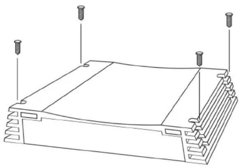
Model XCA 400 and XCA 402
Connect the cinch outputs of your car radio to the cinch connections IN (7) of the amplifier.
rear outputs > connection REAR IN
front outputs > connection FRONT IN
Pay attention to the marking on the cinch connections:
L > left
R > right
If your car radio does not have 4 pre-amplifier outputs please use the so called Y-adapter.
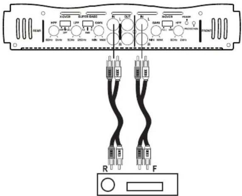
Connection via the cinch inputs
Connect the cinch outputs of your car radio to the cinch connections IN (7) of the amplifier.
Pay attention to the marking on the cinch connections:
L>left
R > right
Connection via the loudspeaker inputs
Plug the delivered loudspeaker connection cable into the connection HIGH IN (9) of the amplifier.
Connect the loudspeaker outputs of your car radio to the terminals of the loudspeaker connection cable.
L+ connection > left positive loudspeaker output
L- connection > left negative loudspeaker output
R- connection > right negative loudspeaker output
R+ connection > right positive loudspeaker output
Connecting the Outputs
Connecting the Loudspeaker Outputs
The power amplifier is supplied with outputs for 4 model XCA 400 and XCA 402 speakers or for 2 model XCA 200 and XCA 202 speakers.
Each of the 2 loudspeaker outputs can also be used in the mono-bridge mode. In fact, only one loudspeaker is powered in this mode, but the available output voltage is higher.
Moreover, one cinch output remains for triggering other system components.

The loudspeakers must be connected with double wires. Insulate The loudspeakers must be connected with double wires. Insulate the naked wire at connecting terminals. Make sure that there are no harp edges which may damage the cables.
Only use loudspeakers which have a sufficiently high loading capacity (see „Technical Data").
Make sure that the loudspeakers have been connected in the correct polarity, i.e. plus and minus signs harmonize!
The connection cables of the loudspeakers are normally coded: Some loudspeaker manufacturers indicate the (+) wire by means of an additional colour stripe, others use a corrugated cable for the (+) terminal and a smooth one for the (-) terminal.
This amplifier has been designed for a loudspeaker impedance of at least 2 ohms (stereo mode) or 4 ohms (mono-bridge mode). Never connect loudspeakers with a lower impedance.
Depending on the model and mode of operation, connect the loudspeaker outputs according to the following schemes. Observe the minimum impedance given for the corresponding mode of operation.
Stereo mode XCA 400 and XCA 402 model
Minimum loudspeaker impedance of 2 ohms

Stereo mode XCA 200 and XCA 202 model
Minimum loudspeaker impedance of 2 ohms

Mono-bridge mode XCa 400 and XCA 402 model
Minimum loudspeaker impedance of 2 ohms (stereo loudspeaker pair) and 4 ohms (subwoofer)

or
Minimum loudspeaker impedance of 4 ohms

Mono-bridge mode XCA 200 and XCA 202 model
Minimum loudspeaker impedance of 4 ohms

Connecting the cinch outputs
Additionally to the loudspeaker outputs, the amplifier is provided with cinch outputs by means of which the input signal can be fed to other components of the car hi-fi system without using adapters.

For connecting the cinch outputs, use only shielded cinch cables suitable for this purpose. The use of any other cable may cause interference.
Keep the length of the connection cables as short as possible.
Do not install the cables in the proximity of other cables. Thus, you avoid interface at the input of the subsequent component.

To avoid distortion or mismatching which could damage the amplifier or the subsequent component, only devices with cinch inputs may be connected to the cinch outputs.
Connect the connection OUT (8) with the input of the subsequent component.
Cinch jacket (L)
input left
Cinch jacket (R)
input right
Operation
Active Duplexer
Model XCA 400 and XCA 402
The amplifier is provided with an active duplexer which allows to switch a high-pass or a low-pass branch for the rear channels. One high-pass branch is provided for the front channels.
The cut-off frequencies can be continuously adjusted.
The amplifier is provided with an active duplexer which allows to switch a high-pass or low-pass branch for the two channels.
The cut-off frequencies can be continuously adjusted.
The frequency duplexer switch X-OVER (4) sets the operating mode of the active duplexer.
FULL:
Active duplexer switched off, the amplifier branch plays back the complete frequency range
HPF:
High-pass duplexer switched on, the amplifier branch only plays back the frequency range above the frequency set via the HPF (1) control unit.
LPF:
Low-pass duplexer switched on, the amplifier branch only plays back the frequency range below the frequency set via the LPF control unit (2).
Super Bass Switch
In addition to this, the amplifier has a bass-boost switch to amplify the low-bass frequencies in two stages.
This option is especially useful to give smaller bass loudspeakers or subwoofoers a little bit of more volume in the low-bass range.
The SUPER BASS
(6) controls the low-bass amplification
Position "0dB":
low-bass amplifier is turned off
Position "6dB":
Low bass is amplified by 6dB
Position "12dB":
Low bass is amplified by 12dB
Initial Startup
After installing and checking all the necessary cable connections you can set the amplifier into operation.
If you have checked the cable connections, reconnect the negative terminal of the battery.
Turn the GAIN control unit (3) counter-clockwise to minimum.
Slide the frequency duplexer switch(es) X-OVER (4) into the position corresponding to your configuration.
Set the cut-off frequencies for the connected loudspeakers via the HPF (1) and LPF (2) control units.
See „Active Filter“
The cut-off frequencies can be set continuously within a range of 50-250Hz or 80-2,000Hz.
During setting operation pay attention to the frequency data given by the loudspeaker manufacturer.
Switch on your car radio.
The indicator LED POWER (5) does light up. If the indicator LED PROTECTION (5) lights, an error has occurred. The amplifier is to be
switched off immediately. In this case, check all connections and loudspeakers. If you cannot detect an error, please contact a specialist for help.
If the indicator LED POWER (5) lights up, set the volume of the car radio to about 75% of the maximum volume.
Now, use the X-OVER control unit(s) (3) to adjust the maximum volume of the loudspeakers to a value which is acceptable for you. If you use several amplifiers, match the volumes of the different amplifiers one to the other.
Then, set an average volume level via the volume control unit of the car radio.
To reach an optimum sound, you can slightly adjust the set cut-off frequencies via the HPF (1) and LPF (2) control units.
If the low-bass playback is too weak, you can activate a two-stage low-bass amplifier via the SUPER BASS switch (6).
Take care that the maximum volume depends on the power capacities of the loudspeaker and amplifier. Excessive volume can damage the loudspeakers and amplifier.
A timing signal can be heard in case of overload.
From now, the total volume is only set by the volume control unit of the car radio.
Make sure that the frequency ranges indicated by the loudspeaker manufacturer are not exceeded during setting operations.
If you use a subwoofer, the change of polarity of the loudspeaker connecting cables may improve the sound quality. Often, the reverse terminal position causes a better bass playback (depending on the place of installation of the subwoofer).
See „Super Bass Switch“
Handling
- An excessive volume inside the car can lead to the reaction that acoustical warning signals are not be heard any longer. This can mean that you and other road users are endangered. Therefore, pay attention to a suitable volume.
- Inattentiveness in traffic can lead to serious accidents. Therefore, the hi-fi system may only be used if the traffic situation allows its operation and if you are not distracted from the traffic by the system.
- The amplifier must be ventilated sufficiently. Never cover the cooling ribs.
- Do not listen to excessively loud music for long periods of time. This can damage your hearing.
Maintenance
Check the technical safety of the amplifier regularly, e.g. for damage to the connection cables or to the housing.
If it can be assumed that a safe operation is not possible any longer, the product must be turned off and precautions are to be taken to ensure that it is not used unintentionally. Disconnect the car power system!
It can be assumed that the safe operation is no longer possible:
- if there is visible evidence that the device has been damaged
- if the appliance does not function for some reason, or
- following considerable stress during transportation.
Observe the following safety instructions without fail before cleaning or servicing the amplifier:

Live components may be exposed if the covering is opened or components are removed.
Therefore, the amplifier must be disconnected from all voltage sources before carrying out servicing or repair works,
Capacitors in the appliance may still be charged even after disconnecting them from all power sources.
Repair work must always be carried out by qualified experts familiar with the hazards involved and with the relevant regulations.
If you have to replace fuses, ensure that you only use fuses of the same type and rated current (see "Technical Data").

It is absolutely impermissible to repair fuses or bridge the fuse holder.
- After disconnecting the appliance from the power source (by disconnecting the car power supply!), carefully remove the FUSE fuse from the fuse holder.
- Replace it by a fuse of the same type.
- Only then the amplifier should be re-connected to the car system and operated.
Disposal

If the appliance has become unusable, dispose of it in accordance with the current statutory regulations.
Troubleshooting
In purchasing the Raveland Amplifier you have acquired a reliable product which has been designed according to the state-of-art technology.
Problems and malfunctions may, however arise.
We would therefore like to describe how you can repair certain malfunctions yourself.

Always adhere to the safety instructions!
| Problem Solution: | |
| No function, the • The GND connection of the connection terminal of the indicator LED power supply is not connected to the car body. POWER (5) does • The REMOTE connection of the connection terminal of the power supply not light up: is not connected to the aerial control output of the car radio. | • +12V are not applied at the +12V connection of the connection terminal of the power supply. • The FUSE fuse of the amplifier or the fuse in the positive connection is defect. |
| Problem: Solution: | |
| The indicator LED • The power (5) lights, but a tone cannot be heard: • The loudspeakers are not properly connected. | The volume control unit of the car radio is set to minimum. The GAIN control unit (3) of the amplifier is set to minimum. The loudspeakers are not properly connected. |
| The indicator LED • The short-circuit protection of the amplifier has been PROTECTION (5) triggered due to a short circuit at the loudspeaker output. lights, but a tone • The temperature protection of the amplifier has been cannot be heard: tr | Short-circuit protection of the amplifier has been short-circuit due to a short circuit at the loudspeaker output. temperature protection of the amplifier has been iggered due to overheating. Allow the device to cool down. |
| One channel does • Check the cinch connections IN (7). not function: • Check the connection of the loudspeakers to the connec-tion terminals and at the loudspeakers themselves. • The balance control at the car radio is not set to its centre position. | One channel does • Check the cinch connections IN (7). not function: • Check the connection of the loudspeakers to the connec-tion terminals and at the loudspeakers themselves. • The balance control at the car radio is not set to its centre position. |
| Disturbing noise: • Bad ground connection of the ground cable, remove possible rust or colour from the contact surfaces. • The mass point of the car radio and of the amplifier are not at the same potential, test different mass points. • The cables of the amplifier are positioned too close to the cables for the ignition system of the vehicle. • The ignition system is not shielded. • The cables of the amplifier input are positioned too close to the power cables. | Ground connection of the ground cable, remove possible rust or colour from the contact surfaces. • The mass point of the car radio and of the amplifier are not at the same potential, test different mass points. • The cables of the amplifier are positioned too close to the cables for the ignition system of the vehicle. • The ignition system is not shielded. • The cables of the amplifier input are positioned too close to the power cables. |
| The device turns • Bad mass contact of the mass connection cable, the mass on and off during point of operation: | Mass contact of the mass connection cable, the mass the cable or of the battery terminal corrodes. • Too low voltage applied at the +12V connection of the connection termini-al for the power supply, the mass point of the cable or of the battery ter-minal corrodes, battery too weak. • Intermittent contact at the REMOTE cable, REMOTE connection of the connection terminal for the power supply shows intermittent contact or is corroded. |
| The playback is given without basses: | One loudspeakers is connected in the wrong way. • The bass control unit of the car radio is set to minimum. • The active duplexer is not set correctly. |
| The playback is given without mid-high-ranges: minimum | The active duplexer is not set correctly. • The high-range control unit of the car radio is set to minimum. |

Repairs other than those just described should only be performed by an authorised electrician.
Technical Data
| XCA 200 XCA 202 XCA 400 XCA 402 | ||||
| Operating voltage 12V= 12V= | 12V= 12V= | |||
| Vehicle flat fuses 1 x 30A 2 x 20A 2 x 30A | 0A 2 x 20A 2 x 30A | |||
| Input sensitivity 0.1-1V 0.1-1V | 0.1-1V 0.1-1V | |||
| Input impedance 10kOhm 10kOhm | Ohm 10kOhm 10kOhm | |||
| Output power 2 x 150W RMS | x 400W RMS 4 | x 120W RMS 4 | x 200W RMS | 2 x 400W RMS |
| 1 x 300W RMS (bridged) (bridged) | 1 x 800W RMS (bridged) | 2 x 240W RMS (bridged) | ||
| 2 x 350W max. | 2 x 1000W max. | 4 x 300W max. | 4 x 500W max. | |
| Output impedance | 2-16 Ohm (Stereo) (Stereo) | 2-16 Ohm (Stereo) (Stereo) | 2-16 Ohm (Stereo) | 2-16 Ohm |
| 4-16 Ohm (bridged) (bridged) | 4-16 Ohm (bridged) | 4-16 Ohm (bridged) | 4-16 Ohm | |
| Crossover frequency | Low pass: | Low pass: | Low pass: | Low pass: |
| 50-250Hz | 50-250Hz | 50-250Hz | 50-250Hz | |
| High pass: | High pass: | High pass: | High pass: | |
| 80-2.000Hz | 80-2.000Hz | 80-2.000Hz | 80-2.000Hz | |
| Deep bass amplification | 0 / 6 / 12 dB | 0 / 6 / 12 dB | 0 / 6 / 12 dB | 0 / 6 / 12 dB |

Introduction
Chere cliente, cher client,
Copyright 2011 by Conrad Electronic SE.
Legal notice
These operating instructions are a publication by Conrad Electronic SE, Klaus-Conrad-Str. 1, D-92240 Hirschau (www.conrad.com).
All rights including translation reserved. Reproduction by any method, e.g. photocopy, microfilming, or the capture in electronic data processing systems require the prior written approval by the editor. Reprinting, also in part, is prohibited.
These operating instructions represent the technical status at the time of printing. Changes in technology and equipment reserved.
Copyright 2011 by Conrad Electronic SE.
F Information legales
Copyright 2011 by Conrad Electronic SE.
NL Colofon
Copyright 2011 by Conrad Electronic SE.
V1_0511_01/HD
- FOR A FAST RESPONSE OF YOUR TECHNICAL ENQUIRIES PLEASE CONTACT OR CONSULT OUR TECHNICAL ADVISORY SERVICE
- OVERVIEW OF COMPONENTS AND CONTROL ELEMENTS
- TABLE OF CONTENTS
- INTENDED USE
- SAFETY INSTRUCTIONS
- PRODUCT DESCRIPTION
- SETUP
- MECHANICAL INSTALLATION
- CONNECTING THE POWER SUPPLY
- CONNECTING THE INPUTS
- MODEL XCA XCA 400 AND XCA 402
- MODEL XCA 200 AND XCA 202
- MODEL XCA 400 AND XCA 402
- CONNECTION VIA THE CINCH INPUTS
- CONNECTION VIA THE LOUDSPEAKER INPUTS
- CONNECTING THE OUTPUTS
- CONNECTING THE LOUDSPEAKER OUTPUTS
- STEREO MODE XCA 400 AND XCA 402 MODEL
- STEREO MODE XCA 200 AND XCA 202 MODEL
- MONO-BRIDGE MODE XCA 400 AND XCA 402 MODEL
- OR
- MONO-BRIDGE MODE XCA 200 AND XCA 202 MODEL
- CONNECTING THE CINCH OUTPUTS
- OPERATION
- ACTIVE DUPLEXER
- FULL
- HPF
- LPF
- SUPER BASS SWITCH
- INITIAL STARTUP
- HANDLING
- MAINTENANCE
- IT IS ABSOLUTELY IMPERMISSIBLE TO REPAIR FUSES OR BRIDGE THE FUSE HOLDER
- DISPOSAL
- TROUBLESHOOTING
- ALWAYS ADHERE TO THE SAFETY INSTRUCTIONS
- TECHNICAL DATA
- INTRODUCTION
- LEGAL NOTICE
- F INFORMATION LEGALES
- NL COLOFON
Brand : Raveland
Model : XCA-400
Category : Receiver