HPL 6STURW - Heat pump DIMPLEX - Free user manual and instructions
Find the device manual for free HPL 6STURW DIMPLEX in PDF.


User questions about HPL 6STURW DIMPLEX
0 question about this device. Answer the ones you know or ask your own.
Ask a new question about this device
Download the instructions for your Heat pump in PDF format for free! Find your manual HPL 6STURW - DIMPLEX and take your electronic device back in hand. On this page are published all the documents necessary for the use of your device. HPL 6STURW by DIMPLEX.
USER MANUAL HPL 6STURW DIMPLEX
natural_image
Technical line drawing of a dual air conditioning unit with meshed panel and cylindrical housing (no text or symbols)Installation and Operating Instruction
Air-to-Water Heat Pump for Outdoor Installation
text_image
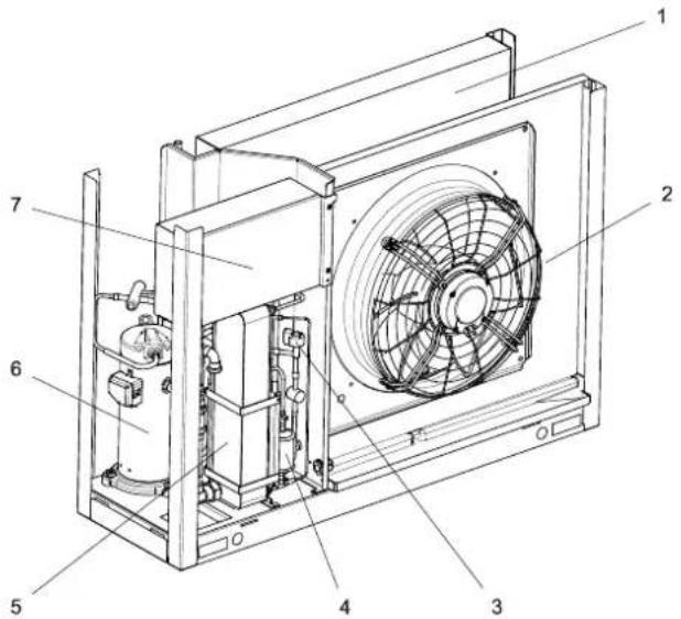
Technical diagram of an industrial fan or compressor unit with numbered components labeled 1 through 7.1) Verdampfer
2) Ventilator
3) Expansionsventil
4) Filtertrockner
5) Verflüssiger
6) Verdichter
7) Schaltkasten
3.2 Schaltkasten
natural_image
Technical line drawing of a mechanical assembly with pipes and housing (no text or symbols)text_image
Technical diagram showing two views of a mechanical device with numbered components and directional arrows indicating motion or assembly.natural_image
Technical line drawing of an air conditioning unit mounted on a brick wall, with no visible text or symbols.natural_image
Empty white rectangle with black border (no text or symbols)Table of contents
1 Please read immediately......EN-2
1.1 Important notes....EN-2
1.2 Intended use......EN-2
1.3 Legal regulations and guidelines....EN-2
1.4 Energy-efficient use of the heat pump......EN-3
2 Intended use of the heat pump ......EN-3
2.1 Area of application....EN-3
2.2 Operating principle......EN-3
3 Scope of supply......EN-4
3.1 Basic device....EN-4
3.2 Switch box.....EN-4
3.3 Hydro-tower HWK 332Econ5S with heat pump manager....EN-4
4 Accessories......EN-5
4.1 Remote control......EN-5
4.2 Building management system......EN-5
5 Transport......EN-5
6 Installation....EN-5
6.1 General......EN-5
6.2 Condensate pipe....EN-6
7 Assembly......EN-6
7.1 General......EN-6
7.2 Connection on heating side....EN-6
7.3 Electrical connection....EN-8
8 Commissioning....EN-8
8.1 General......EN-8
8.2 Preparation......EN-8
8.3 Procedure....EN-8
9 Cleaning / maintenance......EN-9
9.1 Maintenance....EN-9
9.2 Cleaning the heating system ....EN-9
9.3 Cleaning the air system......EN-9
10 Faults / troubleshooting....EN-9
11 Decommissioning / disposal......EN-9
12 Device information ...... EN-10
13 Product information as per Regulation (EU) No 813/2013, Annex II, Table 2......EN-12
Anhang · Appendix · Annexes ...... A-I
Maßbild / Dimension Drawing / Schéma coté...... A-II
Diagramme / Diagrams / Diagrammes....A-III
1 Please read immediately
1.1 Important notes
ATTENTION!
When operating or maintaining a heat pump, the legal requirements of the country where the heat pump is operated apply. Depending on the refrigerant fill quantity, the heat pump must be inspected for leaks at regular intervals by a certified technician, and these inspections must be recorded.
ATTENTION!
When transporting the heat pump, ensure that it is not tilted more than 45^ (in any direction).
ATTENTION!
Do not restrict or block the area around the air intake or outlet.
ATTENTION!
Observe country-specific building regulations!
ATTENTION!
For installation close to walls the physical influences of the building must be considered. No windows or doors should be present in the area surrounding the air outlet of the ventilator.
ATTENTION!
In cases of installation close to a wall, there may be more sediment in the air inlet and outlet areas due to the air current. The colder outside air outlet should discharge in such a way as to not increase the heat losses in heated neighbouring rooms.
ATTENTION!
Installation in a hollow or in an inner courtyard is not permitted because cooled air collects at ground level and is drawn in again by the heat pump during lengthy operation.
ATTENTION!
The frost line can vary according to the climatic region. The regulations of the countries in question must be observed.
ATTENTION!
With fully demineralized water, it is important to ensure that the minimum permissible pH value of 7.5 (minimum permissible value for copper) is complied with. Failure to comply with this value can result in the heat pump being destroyed.
ATTENTION!
Ensure the rotary field is clockwise when connecting the mains cables (if the rotary field is not clockwise, the heat pump will not work properly, is very loud and may cause damage to the compressor).
ATTENTION!
The communication cable is necessary for the function of air-to-water heat pumps in outdoor installation. It must be shielded and laid separately from the mains cable
ATTENTION!
Operating the heat pump at low system temperatures may cause the heat pump to break down completely.
ATTENTION!
Before opening the device, ensure that all circuits are disconnected from the power supply!
ATTENTION!
Work on the heat pump must only be authorised and qualified after-sales service technicians!
1.2 Intended use
This device is only intended for use as specified by the manufacturer. Any other use beyond that intended by the manufacturer is prohibited. This requires the user to abide by the relevant project planning documents. Please refrain from tampering with or altering the device.
1.3 Legal regulations and guidelines
This heat pump is designed for use in a domestic environment according to Article 1, Paragraph 2 k) of EU directive 2006/42/EG (machinery directive) and is thus subject to the requirements of EU directive 2014/35/EU (low-voltage directive). It is thus also intended for use by non-professionals for heating shops, offices and other similar working environments, agricultural establishments and hotels, guesthouses and other residential buildings.
The construction and design of the heat pump complies with all relevant EU directives, DIN/VDE regulations (see CE declaration of conformity).
When connecting the heat pump to the power supply, the relevant VDE, EN and IEC standards are to be adhered to. Any further connection requirements stipulated by the mains supply network operator must also be observed.
When connecting the heating system, all applicable regulations must also be adhered to.
This unit can be used by children aged 8 and over and by persons with limited physical, sensory or mental aptitude or lack of experience and/or knowledge, providing they are supervised or have been instructed in the safe use of the unit and understand the associated potential dangers.
Children must not play with the device. Cleaning and user maintenance must not be carried out by children without supervision.
ATTENTION!
When operating or maintaining a heat pump, the legal requirements of the country where the heat pump is operated apply. Depending on the refrigerant fill quantity, the heat pump must be inspected for leaks at regular intervals by a certified technician, and these inspections must be recorded.
More information can be found in the accompanying log book.
1.4 Energy-efficient use of the heat pump
By operating this heat pump, you are helping to protect the environment. A prerequisite for energy-efficient operation is the correct design of the heat source system and heating system.
It is particularly important for the efficiency of a heat pump to keep the temperature difference between heating water and heat source as small as possible. For this reason, it is advisable to design the heat source and heating system very carefully. A temperaturedifference of approximately one Kelvin (1 °C) increases the power consumption by around 2.5 %. When designing the heating system, it should be borne in mind that special consumers such as domestic hot water preparation should also be taken into consideration and dimensioned for low temperatures. Underfloor heating systems (panel heating) are optimally suited for heat pump use on account of the low flow temperatures (30 °C to 40 °C).
It is important to ensure that the heat exchangers are not contaminated during operation, as this increases the temperature difference, which in turn reduces the COP.
When set correctly, the heat pump manager is also an essential factor in the energy-efficient use of the heat pump. Further information can be found in the heat pump manager operating instructions.
2 Intended use of the heat pump
2.1 Area of application
The air-to-water heat pump is intended exclusively for heating or, depending on the device, also cooling heating water. It can be used in new or existing heating systems.
The heat pump is suitable for mono energy and bivalent operation.
During continuous operation, proper defrosting of the evaporator must be guaranteed by maintaining a heating water return temperature of more than 18 °C .
The heat pump is not designed for the increased heat consumption required when a building is being dried out. For this reason, the additional heat consumption should be met using special devices provided by the customer. For drying out a building in autumn or winter, it is advisable to install a second heat generator (e.g. an electric heating element available as an accessory).
NOTE
The device is not suitable for operation with a frequency converter.
2.2 Operating principle
Heating
Surrounding air is drawn in by the fan and fed through the evaporator (heat exchanger). The evaporator cools the air, i.e. extracts heat from it. This extracted heat is then transferred to the working medium (refrigerant) in the evaporator.
The heat is brought to a higher temperature level by increasing its pressure with the aid of an electrically driven compressor. It is then transferred to the heating water via the liquefier (heat exchanger).
Electrical energy is used to raise the temperature of the heat from the environment to a higher level. Because the energy extracted from the air is transferred to the heating water, this type of device is referred to as an air-to-water heat pump.
The main components of an air-to-water heat pump are the evaporator, fan and expansion valve, as well as the low-noise compressor, liquefier and the electrical control system.
At low ambient temperatures, humidity accumulates on the evaporator in the form of frost, reducing the transfer of heat. Uneven accumulation during this process does not indicate a fault. The evaporator is defrosted automatically by the heat pump as required. Under certain atmospheric conditions, steam may be emitted from the air outlet.
Cooling (device-dependent)
The functions of the evaporator and the liquefier are reversed in the "Cooling" operating mode.
The heating water transfers its heat to the refrigerant via the liquefier, which is now functioning as an evaporator. The refrigerant is brought to a higher temperature level using the compressor. Heat is transferred to the surrounding air via the liquefier (which, in heating operation, functions as an evaporator).
3 Scope of supply
3.1 Basic device
The heat pump is of compact design and the scope of supply includes the components listed.
The refrigeration circuit is "hermetically sealed" and contains the fluorinated refrigerant R410A included in the Kyoto protocol. Information on the GWP value and CO_2 equivalent of the refrigerant can be found in the chapter Device information. The refrigerant is CFC-free, non-ozone depleting and non-combustible
text_image
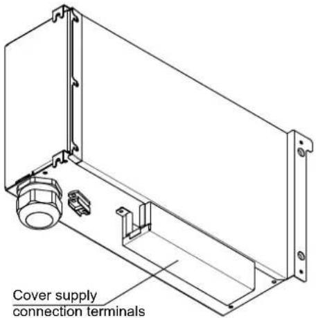
Technical diagram of an industrial fan or compressor unit with numbered components labeled 1 through 7.The switch box is located in the heat pump. After the two screws shown have been loosened, the cover can be removed.
natural_image
Technical line drawing of a mechanical assembly with pipes and structural brackets (no text or symbols)The switch box contains the control elements for the compressor, fan and the controller for the electronic expansion valve.
The supply connections (protected with a cover) are located on the bottom of the switch box.
text_image
Cover supply connection terminals3.3 Hydro-tower HWK 332Econ5S with heat pump manager
The hydro-tower with heat pump manager included in the scope of supply must be used to operate the (reversible) air-to-water heat pump.
The hydro tower constitutes the interface between a heat pump and the heat distribution in the building. The hydro tower contains all hydraulic components required between heat generation and heat distribution with an unmixed heating circuit. A dual differential pressureless manifold with a buffer tank allows an energy-optimised hydraulic integration of the heat generator and the heat distribution.
The integrated heat pump manager is a convenient electronic regulating and control device. It controls and monitors the entire heating system based on the outdoor temperature or room temperature, as well as domestic hot water preparation and safety systems.
The sensor for outside temperature to be mounted on-site incl. fixing materials is included with the heat pump and hydro-tower unit.
The functions and usage of the hydro-tower are described in the operating instructions supplied.
4 Accessories
4.1 Remote control
A remote display adds convenience and is available as a special accessory. Operation and menu navigation are identical to those of the heat pump manager. Connection takes place via an interface (special accessories) with RJ 12 Western plug.

NOTE
In the case of heating controllers with a removable control panel, this can also be used directly as a remote display.
4.2 Building management system
The heat pump manager can be connected to a building management system network via supplementation of the relevant interface plug-in card. The supplementary installation instructions of the interface card must be consulted regarding the exact connection and parameterisation of the interface.
The following network connections can be made on the heat pump manager:
Modbus
EIB, KNX
Ethernet.
5 Transport

ATTENTION!
When transporting the heat pump, ensure that it is not tilted more than 45^ (in any direction).
Transport to the final installation location should be carried out with a pallet. The basic device can be transported with a lift truck, hand truck or by means of 3/4" pipes fed through the holes in the base plate or frame.
6 Installation
6.1 General
The device should always be installed on a permanently smooth, even and horizontal surface. The entire frame should be in direct contact with the ground in order to ensure an adequate soundproof seal and to prevent the water-bearing components from becoming too cold. If this is not the case, additional insulation measures may be necessary. Furthermore, the heat pump should be set up so that the air outlet direction of the fan is perpendicular to the main wind direction to allow unrestricted defrosting of the evaporator. The heat pump is designed for installation on even ground. In the case of different conditions (e.g.: installation on a platform or flat roof) or there is a greater risk of the heat pump tipping over (due to an exposed position or high wind exposure), additional protection against tipping over must be provided. The responsibility for the heat pump installation lies with the specialist system construction company. During the installation, local requirements such as building regulations, static load of the building, and wind exposure must be accounted for.
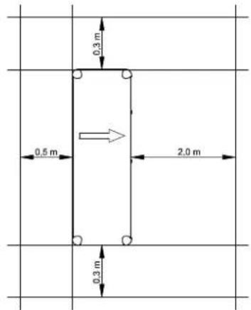
It must be possible to carry out maintenance work without hindrance. This is ensured when observing the distances to solid walls as shown in the figure.
text_image
0.3 m 0.5 m 2.0 m 0.3 mThe specified dimensions are valid for stand-alone installation only.

ATTENTION!
Do not restrict or block the area around the air intake or outlet.

ATTENTION!
Observe country-specific building regulations!

ATTENTION!
For installation close to walls the physical influences of the building must be considered. No windows or doors should be present in the area surrounding the air outlet of the ventilator.

ATTENTION!
In cases of installation close to a wall, there may be more sediment in the air inlet and outlet areas due to the air current. The colder outside air outlet should discharge in such a way as to not increase the heat losses in heated neighbouring rooms.

ATTENTION!
Installation in a hollow or in an inner courtyard is not permitted because cooled air collects at ground level and is drawn in again by the heat pump during lengthy operation.
6.2 Condensate pipe
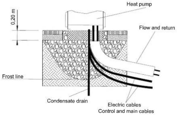
Condensed water that forms during operation must be drained off frost free. To ensure proper drainage, the heat pump must be mounted horizontally. The condensate pipe must have a minimum diameter of 50 mm and must be fed into a sewer in such a way that it is safe from frost. Do not discharge the condensate directly into clearing tanks or cess pits. The aggressive vapours and a condensate pipe laid in an area which is not frost-free can destroy the evaporator.
text_image
0,20 m Heat pump Flow and return Frost line Condensate drain Electric cables Control and main cablesATTENTION!
The frost line can vary according to the climatic region. The regulations of the countries in question must be observed.
7 Assembly
7.1 General
The following connections need to be established on the heat pump:
■Flow and return of the heating system
■Control lines to the heat pump manager
■ Voltage supply
■Condensate drain
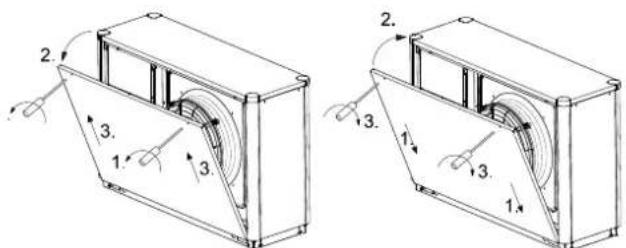
All panelling can be removed to allow accessing the inside of the device.
Loosen the screws for this purpose. The panels can be removed toward the top when slightly tilted.
text_image
Technical diagram showing two views of a mechanical device with numbered components and directional arrows indicating motion or assembly.Opening the cover panels Closing the cover panels
7.2 Connection on heating side
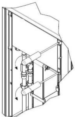
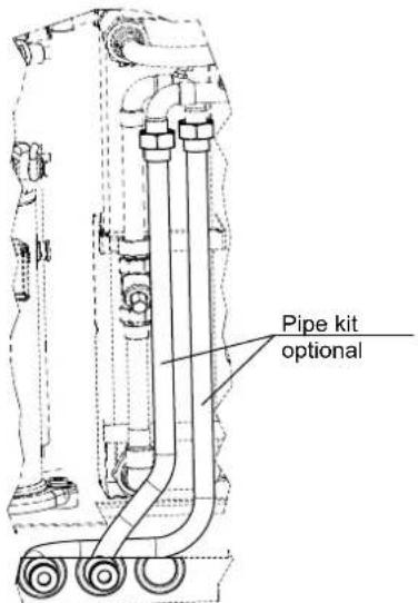
The heating system connections on the heat pump are to be made inside the device. Refer to the device information for the connection sizes. Route the connection hoses out of the device in a downwards direction. An optional pipe kit is available as an accessory, which can be used to lead the connections out to the side. Use a spanner to firmly grip the transitions when connecting the heat pump.
text_image
Pipe kit optionalBefore connecting the heating water system to the heat pump, the heating system must be flushed to remove any impurities, residue from sealants, etc. Any accumulation of deposits in the liquefier could cause the heat pump to completely break down.
Once the heat pump has been connected to the heating system, it must be filled, de-aerated and pressure-tested.
The following points must be observed when filling the system:
■ Untreated filling water and make-up water must be of drinking water quality
(colourless, clear, free of sediments)
■ Filling water and make-up water must be pre-filtered (max. pore size 5 m).
Scale formation in domestic hot water heating systems cannot be avoided, but in systems with flow temperatures below 60 °C, the problem can be disregarded. With high-temperature heat pumps and in particular with bivalent systems in the higher performance range (heat pump + boiler combination), flow temperatures of 60 °C and more can be achieved. The following standard values should therefore be adhered to with regard to the filling and make-up water according to VDI 2035, sheet 1: The total hardness values can be found in the table.
| Total heat output in kW | Total alkaline earths in mol/m3 and/or mmol/l | Specific system volume (VDI 2035) in l/kW | ||
| < 20 | ≥ 20 < 50 | ≥ 50 | ||
| Total hardness in °dH | ||||
| < 50 | ≤ 2.0 | ≤ 16.8 | ≤ 11.2 | < 0.111 |
| 50 - 200 ≤ 2.0 | ≤ 11.2 ≤ 8.4 | |||
| 200 - 600 ≤ 1.5 | ≤ 8.4 | < 0.111 | ||
| > 600 < 0.02 | < 0.111 | |||
- This value lies outside the permissible value for heat exchangers in heat pumps.
Fig. 7.1: Guideline values for filling and make-up water in accordance with VDI 2035
For systems with an above-average specific system volume of 50 l/kW, VDI 2035 recommends using fully demineralized water and a pH stabiliser to minimize the risk of corrosion in the heat pump and the heating system.
ATTENTION!
With fully demineralized water, it is important to ensure that the minimum permissible pH value of 7.5 (minimum permissible value for copper) is complied with. Failure to comply with this value can result in the heat pump being destroyed.
NOTE
The notes/settings in the instructions of the heat pump manager must always be observed and carried out accordingly; not doing so will lead to malfunctions.
Minimum heating water flow rate
The minimum heating water flow rate through the heat pump must be assured in all operating states of the heating system. If the minimum heating water flow rate is not reached, the heat pump is blocked.
The nominal flow rate is specified depending on the max. flow temperature in the device information and must be taken into account during planning. For return temperatures under 30 °C, the flow must be designed for the nominal conditions.
The specified nominal flow rate (See "Device information" on page 14) must be guaranteed in every operating status. An installed flow rate monitoring sensor is used only for switching off the heat pump in the event of an unusual and abrupt drop below the minimum heating water flow rate and not for monitoring and safeguarding the nominal flow rate.
Frost protection
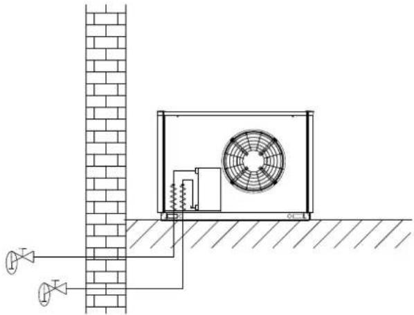
On heat pump systems where protection from frost cannot be guaranteed, there must be an option for draining the system (see figure). The frost protection function of the heat pump manager is active whenever the heat pump manager and the heat circulating pump are ready for operation. If the heat pump is taken out of service or in the event of a power failure, the system has to be drained. If heat pump systems are implemented in buildings where a power failure cannot be detected (holiday homes etc.), the heating circuit should be operated with suitable frost protection.
natural_image
Technical line drawing of an air conditioning unit mounted on a brick wall, showing fan and piping connections (no text or symbols)7.3 Electrical connection
A standard five-core cable is used for connecting the heat pump to the power supply.
The cable must be provided by the customer. The conductor cross section is selected in accordance with the power consumption of the heat pump (see appendix Device information) and the applicable VDE (EN) and VNB regulations.
An all-pole disconnecting device with a contact gap of at least 3 mm (e.g. utility blocking contactor or power contactor) as well as a 3-pole circuit breaker with common tripping for all external conductors must be installed in the power supply (tripping current in compliance with the device information).
The relevant components in the heat pump contain an internal overload protection.
When connecting, ensure that the incoming supply has a clockwise rotating field.
Phase sequence: L1, L2, L3.
ATTENTION!
Ensure the rotary field is clockwise when connecting the mains cables (if the rotary field is not clockwise, the heat pump will not work properly, is very loud and may cause damage to the compressor).
The control voltage is supplied via the heat pump manager. A 3-pole line must be laid for this in accordance with the electrical documentation. Further information on the wiring of the heat pump manager is available in the heat pump manager operating instructions.
A shielded communication line (J-Y(ST)Y ..LG) (not included in the scope of supply) connects the heat pump manager with the WPIO controller installed in the heat pump. More detailed instructions can be found in the heat pump manager operating instructions and in the electrical documentation.
ATTENTION!
The communication cable is necessary for the function of air-to-water heat pumps in outdoor installation. It must be shielded and laid separately from the mains cable
7.3.1 Demand sensor connection
The demand sensor R2.2 is included with the heat pump manager. It must be connected (Cap. 3.2 on page VIII).
NOTE
The return sensor R2 installed in the heat pump is active when the compressor is running and must not be disconnected
8 Commissioning
8.1 General
To ensure that commissioning is performed correctly, it should only be carried out by an after-sales service technician authorised by the manufacturer. This may be a condition for an additional warranty (see "Warranty service").
8.2 Preparation
The following items must be checked prior to commissioning:
All of the heat pump connections must be installed as described in Chapter 7.
All valves which could impair the proper flow of the heating water in the heating circuit must be open.
■ The air intake and air outlet paths must be clear.
■ The fan must turn in the direction indicated by the arrow.
The settings of the heat pump manager must be adapted to the heating system in accordance with the latter's operating instructions.
■ Ensure that the condensate drain functions properly.
8.3 Procedure
The heat pump is commissioned via the heat pump manager. Settings should be made in compliance with the HPM's instructions.
At heating water temperatures below 7 °C, commissioning is not possible. The water in the buffer tank must be heated with the second heat generator to at least 18 °C.
To ensure problem-free commissioning, the following procedure is to be implemented:
1) Close all consumer circuits.
2) Ensure that the heat pump has the correct water flow.
3) Use the manager to select the automatic operating mode.
4) In the special functions menu, start the "Commissioning" program.
5) Wait until a return temperature of at least 25 °C has been reached.
6) Now slowly reopen the heating circuit valves in succession so that the heating water flow rate is constantly raised by slightly opening the respective heating circuit. The heating water temperature in the buffer tank must not be allowed to drop below 20 °C during this process. This ensures that the heat pump can be defrosted at any time.
7) When all heating circuits are fully open and a return temperature of at least 18 °C is maintained, the commissioning is complete.
ATTENTION!
Operating the heat pump at low system temperatures may cause the heat pump to break down completely.
9 Cleaning / maintenance
9.1 Maintenance
To protect the paintwork, avoid leaning anything against the device or putting objects on the device. External heat pump parts can be wiped with a damp cloth and commercially available domestic cleaner.

NOTE
Never use cleaning agents containing sand, soda, acid or chloride, as these can damage the surfaces.
To prevent faults due to sediment in the heat exchanger of the heat pump, ensure that the heat exchanger in the heating system cannot be contaminated. Should operating malfunctions due to contamination still occur, however, the system should be cleaned as described below.
9.2 Cleaning the heating system
The ingress of oxygen into the heating water circuit may result in the formation of oxidation products (rust), particularly if steel components are used. These enter the heating system via the valves, the circulating pumps and/or plastic pipes. A diffusion-resistant installation is therefore essential, especially with regard to the complete piping.

NOTE
We recommend the installation of a suitable corrosion protection system to prevent the formation of deposits (e.g. rust) in the condenser of the heat pump. We recommend equipping diffusion-open heating systems with an electrophysical anti-corrosion system (e.g. ELYSATOR system).
Residue from lubricants and sealants may also contaminate the heating water.
In the event of severe contamination leading to a reduction in the performance of the liquefier in the heat pump, the system must be cleaned by a heating technician.
Based on current information, we recommend using a 5% phosphoric acid solution for cleaning purposes. However, if cleaning needs to be performed more frequently, a 5% formic acid solution should be used.
In both cases, the cleaning fluid should be at room temperature. We recommend flushing the heat exchanger in the direction opposite to the normal flow direction.
To prevent acidic cleaning agents from entering the heating system circuit, we recommend connecting the flushing device directly to the flow and return of the liquefier of the heat pump.
It is then important that the system be thoroughly flushed using appropriate neutralising agents to prevent any damage from being caused by cleaning agent residue remaining in the system.
Acids must be used with care and the regulations of the employers liability insurance associations must be adhered to.
The instructions of the cleaning agent manufacturer must always be observed.
9.3 Cleaning the air system
The evaporator, fan and condensate drain should be cleaned of contamination (leaves, twigs, etc.) before each new heating period. Do this by opening the heat pump as described in Chapter .

ATTENTION!
Before opening the device, ensure that all circuits are disconnected from the power supply!
To prevent the evaporator and the condensate tray from being damaged, do not use hard or sharp objects when cleaning.
Under extreme weather conditions (e.g. snow drifts), ice may form on the air intake and air outlet grids. If this happens, the ice must be removed from the vicinity of the air intake and air outlet grids to ensure that the minimum air flow is maintained.
To ensure proper drainage from the condensate tray, it must be regularly inspected and cleaned, if necessary.
10 Faults / troubleshooting
This heat pump is a quality product and is designed for trouble-free operation. Should a fault occur, however, it will be indicated on the heat pump manager display. In this case, consult the "Faults and troubleshooting" page in the operating instructions of the heat pump manager. If you cannot correct the fault yourself, please contact your after-sales service technician.

ATTENTION!
Work on the heat pump must only be authorised and qualified after-sales service technicians!
11 Decommissioning / disposal
Before removing the heat pump, disconnect it from the power source and close all valves. The heat pump must be dismantled by trained personnel. Observe all environmental requirements regarding the recovery, recycling and disposal of materials and components in accordance with all applicable standards. Particular attention should be paid to the proper disposal of refrigerants and refrigerant oils.
12 Device information
| 1 Type and order code | HPL 6S-TUW HPL 6S-TURW | |||
| 2 Design | ||||
| Heat source Air Air | ||||
| 2.1 Model | Reversible with hydro tower | Reversible with hydro tower | ||
| 2.2 Controller Integrated (hydro tower) Integrated (hydro tower) | ||||
| 2.3 Installation location Haed pump / Hydro tower | Outdoors / Indoors | Outdoors / Indoors | ||
| 2.4 Thermal energy metering | Integrated | Integrated | ||
| 2.5 Performance levels 1 1 | ||||
| 3 Operating limits | ||||
| 3.1 Heating water flow ^1 | °C | up to 60 ± 2 / from 18 | up to 60 ± 2 / from 18 | |
| 3.2 Air (heating) | °C | -22 to +35 | -22 to +35 | |
| 3.3 Cooling water flow | °C | - | +7 to +20 | |
| 3.4 Air (cooling) | °C | - | +15 to +45 | |
| 4 Flow ^2 / sound | ||||
| 4.1 Heating water flow free compression | ||||
| Nominal flow in accordance with EN 14511at A7 / W35...30 | m ^3 /h / Pa | 1.15 / 50200 | 1.15 / 50200 | |
| 4.2 Minimum heating water flow rate Heat pump circuit | m ^3 /h / Pa | 0.66 / 59500 | 0.66 / 59500 | |
| 4.3 Cooling water flow rate / internal pressure differential | ||||
| Nominal flow in accordance with EN 14511A35 / W18...23 | m ^3 /h / Pa | 0.8 / 58500 | 0.8 / 58500 | |
| Minimum cooling water flow rate | m ^3 /h / Pa | 0.8 / 58500 | 0.8 / 58500 | |
| 4.4 Sound power level according to EN 12102Normal operation / reduced operation ^3 ^4 | dB(A) | 56 / 52 | 56 / 52 | |
| 4.5 Sound pressure level at a distance of 10 m (air outlet side) ^5 | 28 / 24 | 28 / 24 | ||
| 4.6 Normal operation / reduced operation ^3 ^4 | dB(A) | 2700 | 2700 | |
| 4.7 Air flow Normal operation | m ^3 /h | 42 | 42 | |
| 4.8 Sound pressure level at a distance of 1m | HWK dB(A) | 35 | 35 | |
| 5 Technical data | ||||
| 5.1 Heat generation | HWK | external | external | |
| 5.2 Buffer tank | HWK | |||
| 5.3 Domestic hot water cylinder | HWK | 64 / 3,0 | 64 / 3,0 | |
| Materials | Enamelled steel complying with DIN 4753 | Enamelled steel complying with DIN 4753 | ||
| Usable capacity | litres | 200 | 200 | |
| Heat exchanger area | m ^2 | 3,0 | 3,0 | |
| Permissible operating temperature | °C | 95 | 95 | |
| Permissible operating pressure | bar | 6,0 | 6,0 | |
| Immersion heater | kW | 1,5 | 1,5 | |
| 5.4 Electrical pipe heater | HWK kW | 2 | 2 | |
| 5.5 Start-to-leak pressure, safety valve | HWK bar | 2,5 | 2,5 | |
| 6 Dimensions, weight and filling quantities | ||||
| 6.1 Device dimensions without connections | H x W x L mm | 945 X 1350 X 600 | 945 X 1350 X 600 | |
| 6.2 Device connections for heating | inches | G 1" external thread | G 1" external thread | |
| 6.3 Weight of the transportable unit(s) incl. packaging | kg | 185 | 185 | |
| 6.4 Refrigerant / total filling weight | type/kg | R410A / 3.4 | R410A / 3.4 | |
| 6.5 GWP value / CO _2 equivalent | --- / t | 2088 / 7 | 2088 / 7 | |
| 6.6 Refrigeration circuit hermetically sealed | yes | yes | ||
| 6.7 Lubricant / total filling quantity | type/litres | Polyolester (POE) / 0.7 | Polyolester (POE) / 0.7 | |
| 6.8 Volume of heating water in device | Litres | 1.9 | 1.9 | |
| 6.9 Device dimensions 6 | HWK HxWxL mm | 1920 x 740 x 950 1920 x 740 x 950 | ||
| 6.10 Tilted dimension HWK mm 2000 2000 | ||||
| 6.11 Device connections HWK | ||||
| for heat generator inches 1" AG/FL 1" AG/FL | ||||
| unmixed heating circuit | inches | 1" AG/FL | 1" AG/FL | |
| for domestic hot water | inches | 1" AG | 1" AG | |
| for circulation pipe | inches | 3/4" IG | 3/4" IG | |
| for expansion vessel | inches 1" | AG/FL 1" AG/FL | ||
| 6.12 Anode diameter | HWK | mm | 26 | 26 |
| 6.13 Anode length | HWK mm | 1100 1100 | ||
| 6.14 Anode connection thread | HWK | inches | G 1" | G 1" |
| 6.15 Weight of the transport unit(s) incl. packaging | HWK | kg | 195 | 195 |
| 7 Electrical connection | ||||
| 7.1 Supply voltage / fusing / RCD type | 3~/N/PE 400 V (50 Hz) / C10 A / A | 3~/N/PE 400 V (50 Hz) / C10 A / A | ||
| 7.2 Control voltage / fusing by WPM | 1~/N/PE 230 V (50 Hz) / 4 AT | 1~/N/PE 230 V (50 Hz) / 4 AT | ||
| 7.3 Degree of protection according to EN 60529 | IP 24 | IP 24 | ||
| 7.4 Starting current limiter | No | No | ||
| 7.5 Rotary field monitoring | No | No | ||
| 7.6 Starting current | A | 28 | 28 | |
| 7.7 Nominal power consumption A2/W35 / max. power consumption 2 | kW | 1.4 / 2.93 | 1.4 / 2.93 | |
| 7.8 Nominal current A2 /W35 / cos φ | A / --- | 2.42 / 0.8 | 2.42 / 0.8 | |
| 7.9 Power consumption of compressor protection (per compressor) | W / --- | - | - | |
| 7.10 Power consumption of fan | W | < 125 | < 125 | |
| 7.11 Control voltage, fusing | HWK | 1~/ N / PE 230V (50Hz) / C13A | 1~/ N / PE 230V (50Hz) / C13A | |
| 7.12 Supply voltage / fusing(Σ P = 3.5 kW) | HWK | 1~/ N / PE 230V (50Hz) / B16A | 1~/ N / PE 230V (50Hz) / B16A | |
| HWK | 3~/ N / PE 400V (50Hz) / B10A | 3~/ N / PE 400V (50Hz) / B10A | ||
| 8 Complies with the European safety regulations | 7 | 7 | ||
| 9 Additional model features | ||||
| 9.1 Type of defrosting | Reverse circulation | Reverse circulation | ||
| 9.2 Frost protection, condensate tray / Water in device protected against freezing 8 | Yes | Yes | ||
| 9.3 Maximum operating pressure (heat sink) | bar | 3.0 | 3.0 | |
| 10 Heat output COP 2 | ||||
| 10.1 Heat output / COP | EN 14511 | |||
| at A-7 / W35 | kW / --- | 3.9 / 2.9 | 3.9 / 2.9 | |
| at A2 / W35 | kW / --- | 5.0 / 3.9 | 5.0 / 3.9 | |
| at A7 / W35 | kW / --- | 6.3 / 4.7 | 6.3 / 4.7 | |
| at A7 / W45 | kW / --- | 5.9 / 3.5 | 5.9 / 3.5 | |
| at A10 / W35 | kW / --- | 6.6 / 4.7 | 6.6 / 4.7 | |
| 11 Cooling capacity / COP 2 4 | ||||
| 11.1 Cooling capacity / COP | EN 14511 | |||
| at A27 / W18 | kW / --- | - | 5.5 / 3.8 | |
| at A27 / W7 | kW / --- | - | 3.7 / 2.7 | |
| at A35 / W18 | kW / --- | - | 4.9 / 3.0 | |
| at A35 / W7 | kW / --- | - | 3.6 / 2.3 | |
-
For air temperatures between -22°C and -5°C, flow temperature increasing from 45? to 60?.
-
These data indicate the size and capacity of the system according to EN 14511. For an analysis of the economic and energy efficiency of the system, other parameters, in particular the defrosting capacity and regulation, should also be taken into consideration. These figures are only achieved with clean heat exchangers. Instructions for care, commissioning and operation can be found in the relevant sections of the installation and operation instructions. The specified values have the following meaning, e.g. A7/W35: outside air temperature 7 °C and heating water flow temperature 35 °C.
-
The heat output and COP is reduced by approx. 5 % in lower operation
-
The maximum sound power level under full load can increase by up to 5 dB(A).
-
The specified sound pressure level represents the free sound area level. The measured value can deviate by up to 16 dB(A), depending on the installation location.
-
Note that additional space is required for pipe connections, operations and maintenance.
-
See CE declaration of conformity
-
The heat circulating pump and the heat pump manager must always be ready for operation.
13 Product information as per
Regulation (EU) No 813/
2013, Annex II, Table 2
| Information requirements for heat pump space heaters and heat pump combination heaters | ||||||
| Model | HPL 6S-TUW | |||||
| Air-to-water heat pump | yes | |||||
| Water-to-water heat pump | no | |||||
| Brine-to-water heat pump | no | |||||
| Low-temperature heat pump | no | |||||
| Equipped with a supplementary heater | yes | |||||
| Heat pump combination heater | yes | |||||
| Parameters shall be declared for medium-temperature application, except for low-temperature heat pumps. For low- temperature heat pumps, parameters shall be declared for low-temperature application. | ||||||
| Parameters shall be declared for average climate conditions: | ||||||
| Item Symbol Value Unit Item Symbol Value | Unit | |||||
| Rated heat output (*) | Prated | 3 | kW | Seasonal space heating energy efficiency | ηs | 114 % |
| Declared capacity for heating foer part load at indoor temperature 20°C and outdoor temperature Tj | Declared coefficient of performance or primary energy ratio for part load at indoor temperature 20 °C and outdoor temperature Tj | |||||
| Tj = -7°C | Pdh | 3,8 kW | Tj = -7°C | COPd | 2,09 - | |
| Tj = +2°C | Pdh | 5,0 kW | Tj = +2°C | COPd | 2,96 - | |
| Tj = +7°C | Pdh | 6,3 kW | Tj = +7°C | COPd | 3,86 - | |
| Tj = +12°C | Pdh | 6,9 kW | Tj = +12°C | COPd | 4,54 - | |
| Tj = bivalent temperature | Pdh | 3,5 kW | Tj = bivalent temperature | COPd | 1,86 - | |
| Tj = operation limit temperature | Pdh | 3,5 kW | Tj = operation limit temperature | COPd | 1,86 - | |
| For air-to-water heat pumps | For air-to-water heat pumps: | |||||
| Tj = -15°C (if TOL < -20°C) | Pdh | -- kW T | = -15°C (if TOL < -20°C) | COPd | -- | |
| Bivalent temperature | Tbiv | -10 | °C | For air-to-water heat pumps:Operation limit temperature | TOL | -10 °C |
| Cycling interval capacity for heating | Pcych | - | kW Cycling interval efficiency | COPcyc | - | |
| Degradation co-efficient (**) | Cdh | 0,90 | - | Heating water operating limit temperature | WTOL | 60 °C |
| Power consumption in modes other than active mode | Supplementary heater | |||||
| Off mode | POFF | 0,015 | kW Rated | heat output (*) | Psup | 0 kW |
| Thermostat-off mode | PTO | 0,020 | kW | Type of energy input | eletrical | |
| Standby mode | PSB | 0,015 | kW | |||
| Crankcase heater mode | PCK | 0,000 | kW | |||
| Other items | ||||||
| Capacity control | fixed | For air-to-water heat pumps: Rated air flow rate, outdoors | -2700 | |||
| Sound power level, indoors/outdoors | LWA | 42/56 | dB | For water-/brine-to-water heat pumps: Rated brine or water flow rate, outdoor heat exchanger | - | m3/h |
| Emissions of nitrogen oxides | NOx | - | mg/kWh | |||
| For heat pump combination heater: | ||||||
| Declared load profile | XL | Water heating energy efficiency | ηwh | 92 % | ||
| Daily electricity consumption | Qelec | 8,75 | kWh | Daily fuel consumption | Qfuel | - kWh |
| Contact details | Glen Dimplex Deutschland GmbH, Am Goldenen Feld 18, 95326 Kulmbach | |||||
| (*) For heat pump space heaters and heat pump combination heaters, the rated output Prated is equal to the design load for heating Pdesignh, and the rated heat output of a supplementary capacity for heating sup(Tj). | ||||||
| (**) If Cdh is not determined by measurement nthen the default degradation is Cdh = 0,9(-) not applicable | ||||||
| Model | HPL 6S-TURW | |||||
| Air-to-water heat pump | yes | |||||
| Water-to-water heat pump | no | |||||
| Brine-to-water heat pump | no | |||||
| Low-temperature heat pump | no | |||||
| Equipped with a supplementary heater | yes | |||||
| Heat pump combination heater | yes | |||||
| Parameters shall be declared for medium-temperature application, except for low-temperature heat pumps. For low- temperature heat pumps, parameters shall be declared for low-temperature application. | ||||||
| Parameters shall be declared for average climate conditions: | ||||||
| Item Symbol Value Unit Item Symbol Value | Unit | |||||
| Rated heat output (*) | Prated | 3 | kW | Seasonal space heating energy efficiency | ηs | 117 % |
| Declared capacity for heating foer part load at indoor temperature 20°C and outdoor temperature Tj | Declared coefficient of performance or primary energy ratio for part load at indoor temperature 20 °C and outdoor temperature Tj | |||||
| Tj = -7°C | Pdh | 3,8 kW | Tj = -7°C | COPd | 2,09 - | |
| Tj = +2°C | Pdh | 5,0 kW | Tj = +2°C | COPd | 2,96 - | |
| Tj = +7°C | Pdh | 6,3 kW | Tj = +7°C | COPd | 3,86 - | |
| Tj = +12°C | Pdh | 6,9 kW | Tj = +12°C | COPd | 4,54 - | |
| Tj = bivalent temperature | Pdh | 3,5 kW | Tj = bivalent temperature | COPd | 1,86 - | |
| Tj = operation limit temperature | Pdh | 3,5 kW | Tj = operation limit temperature | COPd | 1,86 - | |
| For air-to-water heat pumps | For air-to-water heat pumps: | |||||
| Tj = -15°C (if TOL < -20°C) | Pdh | -- kW | Tj = -15°C (if TOL < -20°C) | COPd | -- | - |
| Bivalent temperature | Tbiv | -10 °C | For air-to-water heat pumps:Operation limit temperature | TOL | -10 °C | |
| Cycling interval capacity for heating | Pcych | - | kW Cycling interval efficiency | COPcyc | - | - |
| Degradation co-efficient (**) | Cdh | 0,90 | - | Heating water operating limit temperature | WTOL | 60 °C |
| Power consumption in modes other than active mode | Supplementary heater | |||||
| Off mode | POFF | 0,015 | kW Rated | heat output (*) | Psup | 0 kW |
| Thermostat-off mode | PTO | 0,020 | kW | Type of energy input | eletrical | |
| Standby mode | PSB | 0,015 | kW | |||
| Crankcase heater mode | PCK | 0,000 | kW | |||
| Other items | For air-to-water heat pumps: Rated air flow rate, outdoors | -2700 | m3/h | |||
| Capacity control | fixed | |||||
| Sound power level, indoors/outdoors | LWA | 42/56 | dB | For water-/brine-to-water heat pumps: Rated brine or water flow rate, outdoor heat exchanger | - | m3/h |
| Emissions of nitrogen oxides | NOx | - | mg/kWh | |||
| For heat pump combination heater: | ||||||
| Declared load profile | XL | Water heating energy efficiency | nwh | 92 % | ||
| Daily electricity consumption | Qelec | 8,75 | kWh | Daily fuel consumption | Qfuel | - kWh |
| Contact details | Glen Dimplex Deutschland GmbH, Am Goldenen Feld 18, 95326 Kulmbach | |||||
| (*) For heat pump space heaters and heat pump combination heaters, the rated output Prated is equal to the design load for heating Pdesignh, and the rated heat output of a supplementary capacity for heating sup(Tj). | ||||||
| (**) If Cdh is not determined by measurement nthen the default degradation is Cdh = 0,9(--) not applicable | ||||||
Table des matières
text_image
Technical diagram of an air conditioning unit with numbered components for identificationnatural_image
Technical line drawing of a mechanical assembly with pipes and housing (no text or symbols)text_image
Technical diagram of a mechanical device with numbered components and directional arrows indicating motion or assembly.text_image
Technical diagram of a mechanical device with numbered components and directional arrows indicating motion or assembly.natural_image
Technical line drawing of an air conditioning unit mounted on a brick wall, with no visible text or symbols.line
| Lufteintrittstemperatur in [°C] | Air inlet temperature in [°C] | Temperature d'entrée d'air en [°C] | |---|---|---| | -20 | 1.5 | 1.3 | | -15 | 2.0 | 1.6 | | -10 | 2.5 | 1.9 | | -5 | 3.0 | 2.2 | | 0 | 3.5 | 2.5 | | 5 | 4.0 | 2.8 | | 10 | 4.5 | 3.1 | | 15 | 5.0 | 3.4 | | 20 | 5.5 | 3.7 | | 25 | 6.0 | 4.0 | | 30 | 6.5 | 4.3 | | 35 | 7.0 | 4.6 | The chart displays a line graph with three lines corresponding to values 35, 45, and 55, indicating that performance coefficient increases with temperature for each line. The x-axis represents temperature in degrees Celsius, and the y-axis represents the coefficient of performance. The legend is implicit in the line labels.2.2 Kennlinien Kühlen / Characteristic curves for cooling operation / Courbes caractéristiques mode rafraîchissement

line
| Temperature (°C) | Lufteintrittstemperatur (kW) | Water outlet temperature (°C) | | ----------------- | ---------------------------- | ------------------------------ | | 18 | 4.0 | 4.0 | | 7 | 2.0 | 4.0 |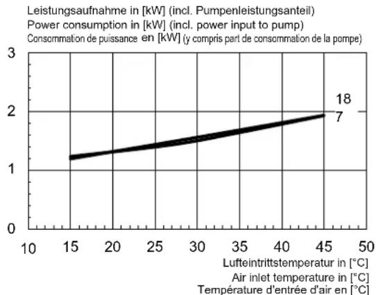
line
| Lufteintrittstemperatur in [°C] | Power consumption in [kW] | | ------------------------------ | -------------------------- | | 15 | 1.2 | | 45 | 2.0 |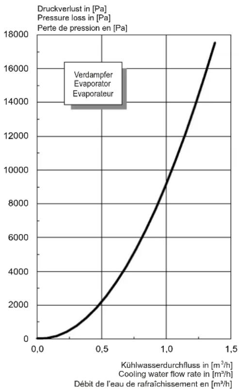
line
| Kuhlwasserdurchfluss in [m³/h] | Cooling water flow rate in [m³/h] | Pressure loss in [Pa] | | ------------------------------ | ----------------------------------- | --------------------- | | 0.0 | 0 | 0 | | 0.5 | 2000 | 2000 | | 1.0 | 9000 | 9000 | | 1.5 | 18000 | 18000 |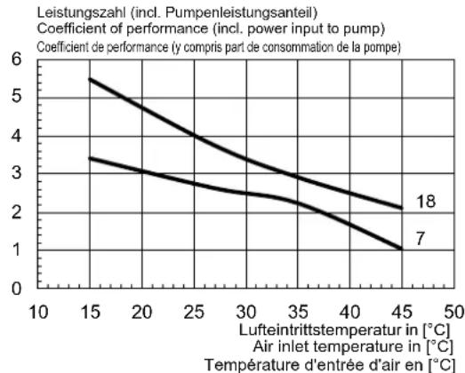
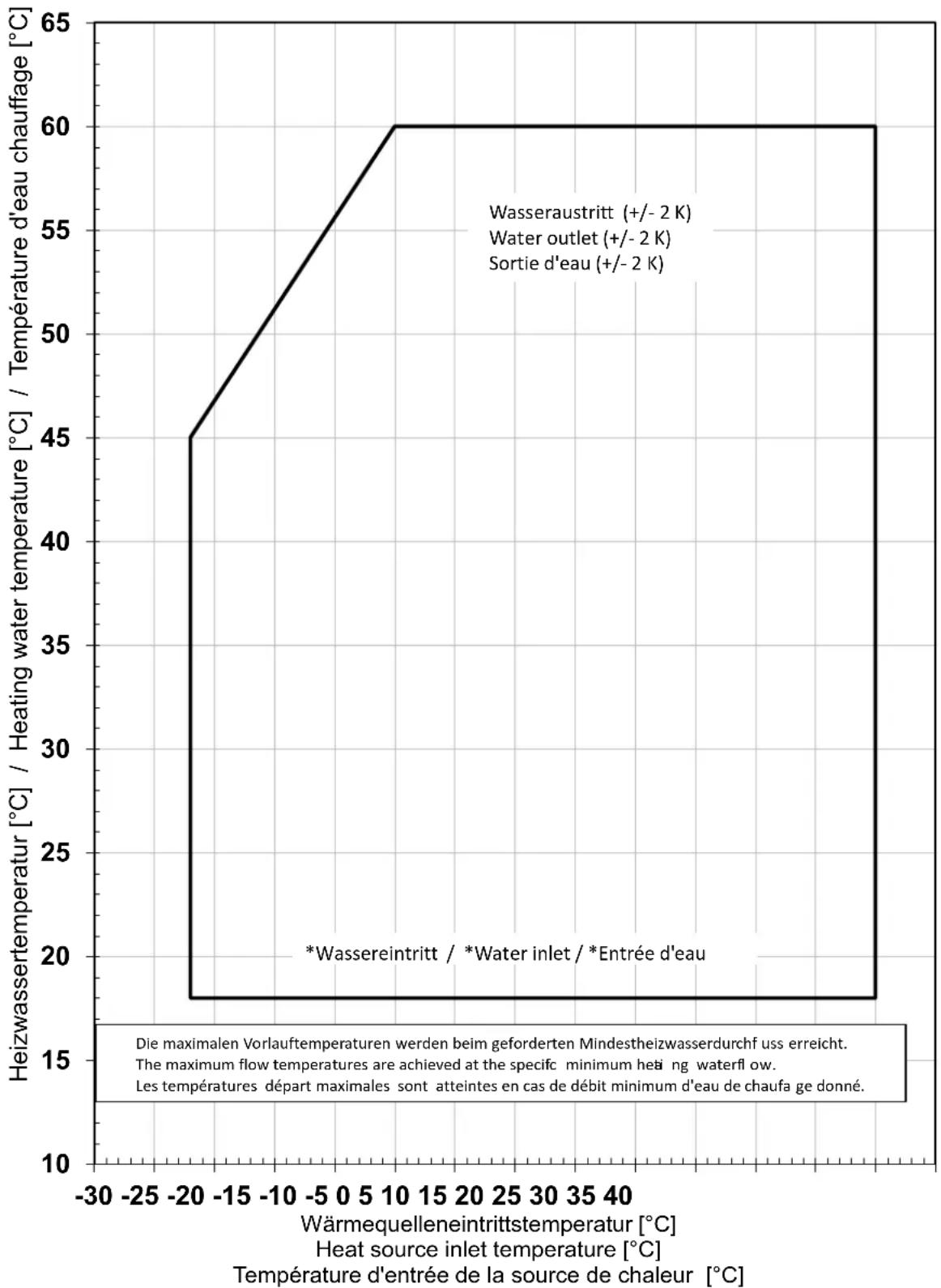
2.3 Einsatzgrenzendiagramm Heizen / Operating limits diagram heating / Diagramme des seuils d'utilisation chauffage
line
| Wärmequelleneintrittstemperatur [°C] | Heizwassertemperatur [°C] / Heating water temperature [°C] / Température d'eau chauffage [°C] | | ----------------------------------- | ------------------------------------------------------------------------------------------ | | -20 | 45 | | 10 | 60 | | 40 | 60 |*For air-to-water heat pumps the minimum heating water temperature is the minimum return temperature
flowchart
Electrical wiring diagram showing connections between WPM Econ5S module, fieldbus card, and various PLCs (N1, N2, N3, N4) with labeled terminals and components.You can find and download the current CE conformity declaration at: