
K 160 - Heating Heylo - Free user manual and instructions
Find the device manual for free K 160 Heylo in PDF.

| Brand | Heylo |
| Model | K 160 |
| Category | Auxiliary warm air heater |
| Fuel type | HVO 100 biofuel, Diesel B7, Kerosene |
| Heating capacity | 160 kW (estimated) |
| Tank capacity | Approximately 40 L (estimated) |
| Power supply | 230 V / 50 Hz (see rating plate) |
| Dimensions (L x W x H) | 1200 x 600 x 800 mm (estimated) |
| Weight | Approximately 60 kg (estimated) |
| Operating modes | Heating and ventilation only |
| Connectivity | InfoAir (remote monitoring via GPS, scheduling, notifications) |
| Room thermostat | Connector for external thermostat (optional) |
| Safety | Automatic shutdown in case of overheating, flame sensors, shutdown on voltage fault |
| Maintenance | Annual cleaning of fuel filters; preventive maintenance by authorized center |
| Repairability | Original spare parts; repairs exclusively by technical support center |
| Safety distance | 1.5 m from sides, 2.5 m from air outlet |
| Required ventilation | Use only in well-ventilated areas |
| Warranty | See supplier conditions |
Frequently Asked Questions - K 160 Heylo
User questions about K 160 Heylo
0 question about this device. Answer the ones you know or ask your own.
Ask a new question about this device
Download the instructions for your Heating in PDF format for free! Find your manual K 160 - Heylo and take your electronic device back in hand. On this page are published all the documents necessary for the use of your device. K 160 by Heylo.
USER MANUAL K 160 Heylo
natural_image
Icon of an open book with an exclamation mark, enclosed in a diamond shape with a yellow diagonal stripe (no text or symbols)USER AND MAINTENANCE MANUAL
HEYLO
K 120 - K 160
| en | it | de | es | fr | nl | pt | da | fi | no | sv | pl | ru | cs | hu | sl | tr | hr | lt |
| lv | et | ro | sk | bg | uk | bs | el | zh | kk |
NOTE:
TECHNICAL DATA TABLE - TABELLA DATI TECNICI - TECHNISCHE DATENTABELLE - TABLA DE DATOS TÉCNICOS - TABLEAU DES DONNÉES TECHNIQUES - TABEL TECHNISCHE GEGEVENS - TABELA DE DADOS TÉCNICOS - TEKNISK DATATABEL - TEKNISTEN TIETOJEN TAULUKKO - TABELL FOR TEKNISKE DATA - TABELL MED TEKNISKA EGENSKAPER - TABELA DANYCH TECHNICZNYCH - ТАБЛИЦЕ ТЕХНИЧЕСКИХ ДАННЫХ - TABULKA TECHNICKÝCH ÚDAJŮ - MŰSZAKI ADATOK TÁBLÁZATA - TEHNIČNI PODAT-KI - TEKNÍK VERİLER TABLOSUNDA - TABLICI S TEHNIČKIM PODACIMA - TECHNINIŲ DUOMENU LENTELĖJE - TEHNISKO DATU TABULA - TEHNILISTE ANDMETE TA-BEL - TABELUL CU DATE TEHNICE - TABULKA TECHNICKÝCH ÚDAJOV - ТАБЛИЦА ТЕХНИЧЕСКИ ДАННИ - ТАБЛИЦІ ТЕХНІЧНИХ ДАНИХ - TABELI SA TEHNIČKIM PODACIMA - PÍNAKÍDA TÓN TEXNIKΩΝ ΣΤΟΙΧΕΙΩΝ - 技术参数 - ТЕХНИКАЛЫҚ КӨРСЕТКІШТЕР КЕСТЕСІ
| K 120 K 160 | |||
 | MAX | 125 kW-кВт107.500 kcal/h-ккал/ч427.000 Btu/h-БТЕ/ч | 160 kW-кВт137.600 kcal/h-ккал/ч546.000 Btu/h-БТЕ/ч |
 | 9.200 m^3/h - m^3/ч 11.500 m^3/h - m^3/ч | ||
 | 10 kg/h-кг/ч 12,7 kg/h-кг/ч | ||
 | DIESEL-HVO100-KEROSENEDизель-HVO100-керосин | DIESEL-HVO100-KEROSENEDизель-HVO100-керосин | |
 | ~220-240 V-B (-15%÷10%)50 Hz-Гц6,9 A 1,5 kW-кВт | ~220-240 V-B (-15%÷10%)50 Hz-Гц7,3 A 1,65 kW-кВт | |
 | 2,5 gal/h 60°B DELAVAN | 3,25 gal/h 60°B DELAVAN | |
 | 1.100 kPa-кПа11 bar-бар | 1.100 kPa-кПа11 bar-бар | |
 | 300 Pa-Па 290 Pa-Па | ||
 | 0,1 mbar-мбар 0,1 mbar-мбар | ||
 | 280 kg-кг 280 kg-кг | ||
 | 2,5 mm^2 (MAX. 30m) 4 mm^2 (MAX. 50m) | 2,5 mm^2 (MAX. 30m) 4 mm^2 (MAX. 50m) | |

IMPORTANT (if applicable, see data label): Please use only one of the following fuels: HVO 100 (*) Biofuel, Diesel B7 and Kero-

IMPORTANT: In order to have a correct function you must use an electrical generator in class G3 or more (frequency variation ± 1% , on variation ± 2% ). The maximum power of electrical generator must be three time the nominal power of device that you must connect.
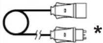
* The extension cords are suggested according rated input voltage. Do only use approved cables and plugs. Do not connect more than one extension cord.
NOTE:
PICTURES - FIGURE - ABBILDUNGEN - FIGURAS - FIGURES - FIGUREN - FIGURAS - FIGURER - KUVAT - FIGURER - FIGUR - RYSUNKI - РИСУНКИ - ОВРАЗКУ - АВРАК - SLIKE - ŞEKİLLER - SLIKE - PAVEIKSLÈLIAI - ATTËLI - JOONISED - IMAGINI - ОВРАЗ- КУ - ФИГУРА - МАЛЮНКИ - SLIKE - EIKONEΣ - 图 - СУРЕТТЕР
natural_image
Line drawing of a wheeled industrial cart with wheels and a cylindrical wheel (no text or symbols)PICTURES - FIGURE - ABBILDUNGEN - FIGURAS - FIGURES - FIGUREN - FIGURAS - FIGURER - KUVAT - FIGURER - FIGUR - RYSUNKI - РИСУНКИ - ОВРАЗКУ - АВРАК - SLIKE - ŞEKİLLER - SLIKE - PAVEIKSLÈLIAI - ATTËLI - JOONISED - IMAGINI - ОВРАЗ- КУ - ФИГУРА - МАЛЮНКИ - SLIKE - EIKONEΣ - 图 - СУРЕТТЕР
natural_image
Technical line drawing of a mechanical device with wheels and mounting brackets (no text or symbols)PICTURES - FIGURE - ABBILDUNGEN - FIGURAS - FIGURES - FIGUREN - FIGURAS - FIGURER - KUVAT - FIGURER - FIGUR - RYSUNKI - РИСУНКИ - ОВРАЗКУ - АВРАК - SLIKE - ŞEKİLLER - SLIKE - PAVEIKSLÈLIAI - ATTËLI - JOONISED - IMAGINI - ОВРАЗ- КУ - ФИГУРА - МАЛЮНКИ - SLIKE - EIKONEΣ - 图 - СУРЕТТЕР
PICTURES - FIGURE - ABBILDUNGEN - FIGURAS - FIGURES - FIGUREN - FIGURAS - FIGURER - KUVAT - FIGURER - FIGUR - RYSUNKI - РИСУНКИ - ОВРАЗКУ - АВРАК - SLIKE - ŞEKİLLER - SLIKE - PAVEIKSLÈLIAI - ATTËLI - JOONISED - IMAGINI - ОВРАЗ- КУ - ФИГУРА - МАЛЮНКИ - SLIKE - EIKONEΣ - 图 - СУРЕТТЕР
natural_image
Line drawing of an electrical cabinet with a pipe fitting and labeled 'IN' (no text or symbols beyond basic labels)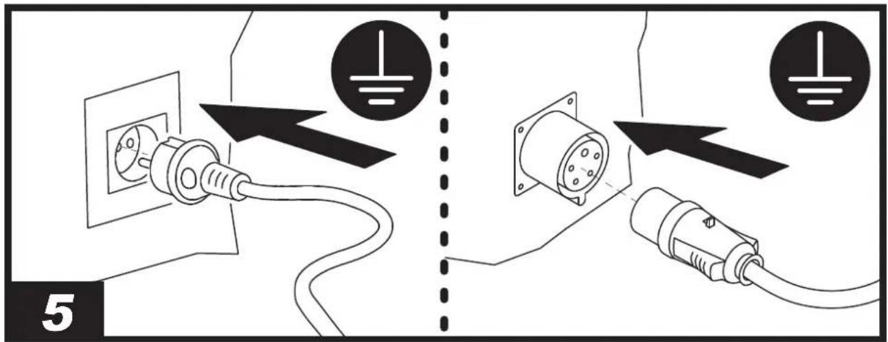
natural_image
Illustration of an electrical testing setup with a device, cable, and a meter (no text or symbols visible)PICTURES - FIGURE - ABBILDUNGEN - FIGURAS - FIGURES - FIGUREN - FIGURAS - FIGURER - KUVAT - FIGURER - FIGUR - RYSUNKI - РИСУНКИ - ОВРАЗКУ - АВРАК - SLIKE - ŞEKİLLER - SLIKE - PAVEIKSLÈLIAI - ATTËLI - JOONISED - IMAGINI - ОВРАЗ- КУ - ФИГУРА - МАЛЮНКИ - SLIKE - EIKONEΣ - 图 - СУРЕТТЕР
natural_image
Technical line drawing of a mechanical device with a rotating arrow indicating motion (no text or symbols)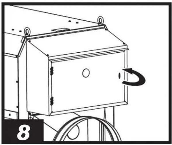
natural_image
Technical line drawing of a mechanical device with a rotating component and wheels (no text or symbols)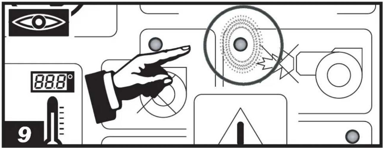
natural_image
Line drawing of a hand pressing a button on a device panel (no text or symbols)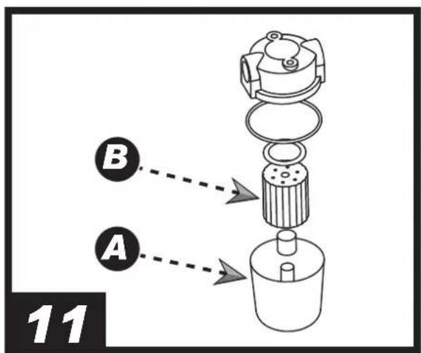
PICTURES - FIGURE - ABBILDUNGEN - FIGURAS - FIGURES - FIGUREN - FIGURAS - FIGURER - KUVAT - FIGURER - FIGUR - RYSUNKI - РИСУНКИ - ОВРАЗКУ - АВРАК - SLIKE - ŞEKİLLER - SLIKE - PAVEIKSLÈLIAI - ATTËLI - JOONISED - IMAGINI - ОВРАЗ- КУ - ФИГУРА - МАЛЮНКИ - SLIKE - EIKONEΣ - 图 - СУРЕТТЕР
natural_image
Abstract geometric shape composed of black and white rectangles (no text or symbols)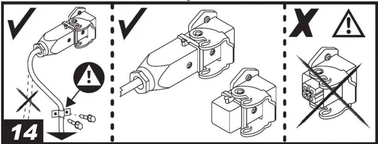
PICTURES - FIGURE - ABBILDUNGEN - FIGURAS - FIGURES - FIGUREN - FIGURAS - FIGURER - KUVAT - FIGURER - FIGUR - RYSUNKI - РИСУНКИ - ОВРАЗКУ - АВРАК - SLIKE - ŞEKİLLER - SLIKE - PAVEIKSLÈLIAI - ATTËLI - JOONISED - IMAGINI - ОВРАЗ- КУ - ФИГУРА - МАЛЮНКИ - SLIKE - EIKONEΣ - 图 - СУРЕТТЕР
NOTE:
THE REMOTE MONITORING
OF PORTABLE HEATERS
Congratulations! You have just purchased a heater which is compatible with the remote monitoring system InfoAir.
InfoAir is a cloud-based solution designed to remotely control, monitor and analyse your heaters' job.
What you get with InfoAir:
• Simplified fleet management
• Enhanced safety and compliance
• Preventive maintenance and minimised downtime
• Optimal resource allocation
• Cost savings and customer satisfaction
• Remote troubleshooting and technical support
Scan the QR code and learn more:

Get started now with 1-month free trial!

▶▶▶en - PRODUCT COMPATIBLE WITH "InfoAir" TECHNOLOGY
What is "InfoAir"?
It is a cloud-based solution for remote monitoring of the hot air heater in real time, via computer or smartphone (wherever the user is, the product must be on stand-by to monitor the heater).
InfoAir' technology allows:
▶ Tracking GPS;
▶ Schedule power on/off;
▶ Product status;
- Malfunction notification and much more information.
When purchase, the heater is already set up to benefit from "InfoAir" technology, but the service is not active. To use "InfoAir" technology, a subscription must be taken out on the appropriate portal, indicating the IMEI code located inside the burner compartment and the serial number indicated on the data label.
▶▶▶ it - PRODOTTO COMPATIBILE CON TECNOLOGIA "InfoAir"
Cos'è "InfoAir"?
▶▶▶de - PRODUKT KOMPATIBEL MIT "InfoAir"-TECHNOLOGIE
Was ist "InfoAir"?
es - PRODUCTOS COMPATIBLES CON LA TECNOLOGÍA "InfoAir"
¿Qué es "InfoAir"?
▶▶▶fr - PRODUIT COMPATIBLE AVEC LA TECHNOLOGIE "InfoAir
▶▶▶nl - PRODUCT COMPATIBEL MET "InfoAir"-TECHNOLOGIE
Wat is "InfoAir"?
▶▶▶pt - PRODUTO COMPATÍVEL COM A TECNOLOGIA "InfoAir
▶▶▶da - PRODUKTER, DER ER KOMPATIBLE MED "InfoAir"-TEKNOLOGI
Hvad er "InfoAir"?
▶▶▶no - PRODUKTER SOM ER KOMPATIBLE MED "InfoAir"-TEKNOLOGI
Hva er "InfoAir"?
▶▶▶sv - PRODUKT SOM ÄR KOMPATIBEL MED "InfoAir"-TEKNIKEN
Vad är "InfoAir"?
▶▶▶pl - PRODUKT KOMPATYBILNY Z TECHNOLOGIA "InfoAir"
▶▶▶cs - PRODUKT KOMPATIBILNÍ S TECHNOLOGIÍ "InfoAir"
Co je "InfoAir"?
▶▶▶hu - "InfoAir" TECHNOLÓGIÁVAL KOMPATIBILIS TERMÉK
Mi az "InfoAir"?
▶▶▶sl - IZDELEK, SODOBEN S TEHNOLOGIJO "InfoAir"
Kaj je "InfoAir"?
▶▶▶Iv - PRODUKTS. KAS SADERIGS AR "InfoAir" TEHNOLOGIJU
Kas ir "InfoAir"?
▶▶▶sk - PRODUKT KOMPATIBILNÝ S TECHNOLÓGIOU "InfoAir"
Čo je "InfoAir"?
▶▶▶bs - PROIZVOD KOMPATIBILAN SA "InfoAir" TEHNOLOGIJOM
Šta je "InfoAir"?
IMPORTANT: READ AND UNDERSTAND THIS OPERATIONAL MANUAL PRIOR TO ASSEMBLING, STARTING UP OR CONDUCTING MAINTENANCE ON THIS HEATER. USING THE HEATER INCORRECTLY CAN CAUSE SERIOUS OR FATAL INJURIES. KEEP THIS MANUAL FOR FURTHER REFERENCE.
▶▶▶1. DESCRIPTION
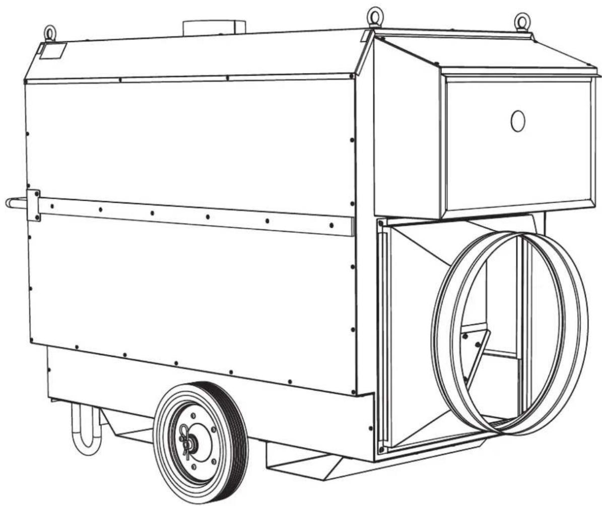
(Pic. 1)
This series of heaters is particularly suited to heating medium to large-sized rooms or areas.
These hot air heaters have been designed according to the most modern criteria of safety, functionality and durability. The safety devices on the heater ensure correct operation at all times.
▶▶▶2. SAFETY INFORMATION
WARNINGS
IMPORTANT: DO NOT USE THE HEATER FOR HEATING LIVING AREAS, IN ANY CASE, REFER TO NATIONAL REGULATIONS.
IMPORTANT: THE AIR HEATER IS DESIGNED FOR PROFESSIONAL, MOBILE AND TEMPORARY APPLICATIONS. IT HAS NOT BEEN DESIGNED FOR DOMESTIC USE NOR FOR THERMAL COMFORT OF PERSONS.
IMPORTANT: THE HEATER IS NOT SUITABLE FOR USE BY PERSONS (INCLUDING CHILDREN) WITH REDUCED PHYSICAL, SENSORY AND MENTAL CAPABILITIES, OR INEXPERIENCED PERSONS, UNLESS THEY ARE SUPERVISED BY A PERSON RESPONSIBLE FOR THEIR SAFETY. CHILDREN MUST BE SUPERVISED TO MAKE SURE THEY DO NOT PLAY WITH THE HEATER.
IMPORTANT: THE MANUFACTURER ACCEPTS NO LIABILITY FOR DAMAGE TO PROPERTY OR PERSONAL INJURY CAUSED BY UNAUTHORIZED MODIFICATIONS TO THE HEATER.
⚠️ DANGER: IMPROPER USE OF THIS HEATER CAN CAUSE DAMAGE, INJURIES, BURNS, EXPLOSIONS, ELECTRIC SHOCK, POISONING OR ENDANGER LIFE. THE FIRST SYMPTOMS OF CARBON MONOXIDE ASPHYXIATION ARE SIMILAR TO THOSE OF FLU WITH HEADACHE, DIZZINESS AND/OR NAUSEA. THESE SYMPTOMS COULD BE CAUSED BY THE FAULTY OPERATION OF THE HEATER. IF THESE SYMPTOMS OCCUR, GO OUTDOORS IMMEDIATELY AND HAVE THE HEATER REPAIRED BY A TECHNICAL SUPPORT CENTRE.
DANGER: THE HEATER, WHEN CONTROLLED BY A ROOM THERMOSTAT (WHERE PROVIDED), CAN SWITCH ON AT ANY TIME.
▶▶2.1. GENERAL INFORMATION
▶2.1.1. Observe all local legislation and current regulations when using the heater.
▶2.1.2. Heaters used in the vicinity of tarpaulins, curtains or other similar materials must respect the minimum safety distance. In any case, comply with all local legislation and current regulations.
▶2.1.3. Never use the heater in environments where flammable elements are present.
▶2.1.4. Keep children and animals at a safe distance from the heater.
▶2.1.5. The minimum recommended safety distance between the heater and flammable elements, including the power cable, is 1.5 m (3.2 ft) and 2.5 m (8.2 ft) from the air outlet.
▶2.1.6. Before putting the heater into operation, make sure that the fire-fighting devices are ready for use.
▶2.1.7. The heater must be used in well-ventilated areas.
▶2.1.8. The heater must be used on stable and level surfaces.
▶2.1.9. Electrically supply the heater only with current having the voltage and frequency specified on the identification plate attached to the product.
▶2.1.10. Electrically supply the heater only with electric extension cords of a suitable cross-section, properly earthed.
▶2.1.11. Do not block or partialise the air inlet and outlet of the heater.
▶2.1.12. Disconnect the heater from the power supply when the product is not used for an extended period of time.
▶2.1.13. When the heater is hot, or connected to the power supply, or in operation, it must never be moved, handled, refuelled or subjected to any maintenance work.
▶2.1.14. Any repair work on the heater must be carried out by the technical support centre.
▶2.1.15. Use only original spare parts, strictly observing the basic configuration.
▶2.1.16. Only apply original kits to the heater.
▶▶2.2. REFUELLING
▶2.2.1. Only refuel the heater with the type of fuel specified on the identification plate attached to the product.
▶2.2.2. Switch off and wait for the heater to cool down completely before refuelling.
▶2.2.3. Personnel responsible for refuelling the heater must be careful and use the appropriate safety devices.
▶2.2.4. Fuel must be stored in accordance with current regulations.
▶2.2.5. Fuel tanks must be kept at a minimum safety distance from the heater, in accordance with current regulations.
▶▶▶3. UNPACKING
WARNING: THE PACKAGING MATERIAL IS NOT A TOY FOR CHILDREN. KEEP THE PLASTIC BAG OUT OF REACH OF CHILDREN; DANGER OF SUFFOCATION!
▶3.1. Remove all packaging materials used to pack and ship the heater. Dispose of them in compliance with current regulations.
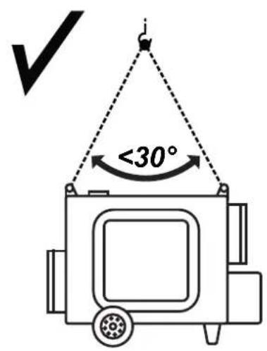
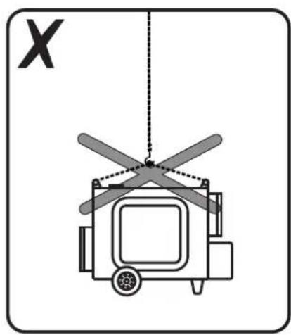
▶3.2. If the heater is placed on the platform, lower it gently using suitable devices and tools, in accordance with national regulations and current standards. It can be lifted with the forklift truck, by using suitable chains and suspension hooks (the heater is equipped with eyebolts).
▶3.3. Check for any damage incurred during transport. If the heater appears damaged, immediately inform the dealer from whom it was purchased.
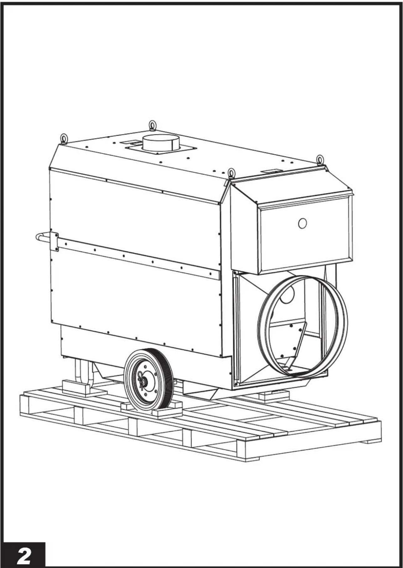
▶▶▶4. ASSEMBLY
(Pic. 2)
These heaters are equipped with handles, brackets, supports, etc. depending on the model. These parts, which come with the relative nuts and bolts, are located in the heater's packaging.
▶▶▶5. FUEL
WARNING: THE HEATER ONLY WORKS WITH HVO 100 BIOFUEL, DIESEL B7 OR KEROSENE.
To avoid any fire or explosion hazard, never use petrol, naphtha, solvents for paints, alcohol or other highly inflammable fuels.
Use non-toxic, anti-freeze additives in case of very low temperatures.
It is recommended to use winter fuel below 5^ C ( 41^ F).
▶▶▶6. OPERATING PRINCIPLES
The burner pump draws the fuel from the tank and sends it to the pressurised nozzle where it is nebulised and mixed with combustion air in the combustion chamber. A spark triggers combustion while the waste fumes are expelled from the chimney. A series of sensors constantly check the correct operation of the heater, stopping the cycle in the case of a fault. The fan, located at the rear of the heater, cools the combustion chamber and the flue gas pass, transferring the heat from the latter into the environment.
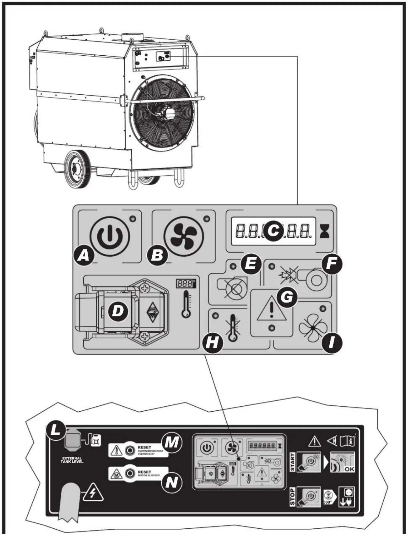
▶▶▶7. CONTROL PANEL
(Pic. 3)
A. HEATING ON/OFF BUTTON: On/off button for "HEATING" mode.
B. FAN ON/OFF BUTTON: On/off button for "VENTILATION-only" mode.
C. Display.
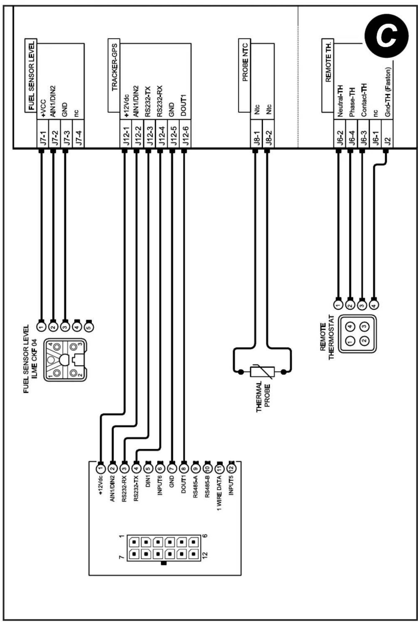
D. Remote room thermostat connector (room thermostat optional).
E. Burner voltage failure alarm light.
F. Burner blocked alarm light.
G. Electricity voltage presence light (the light only lights up in stand-by mode).
H. Over-temperature thermostat alarm light.
I. Fan blocked alarm light.
L. External tank level probe connector (probe optional).
M. Overtemperature thermostat reset button.
N. Motor blocked reset button (depending on model).
O. Cable reel support.
P. Remote room thermostat cable tear-proof clip.
▶▶▶8. OPERATION
WARNING: CAREFULLY READ THE "SAFETY INFORMATION" BEFORE SWITCHING ON THE HEATER.
▶▶8.1. SWITCHING ON THE HEATER
▶8.1.1. Follow all the safety instructions.
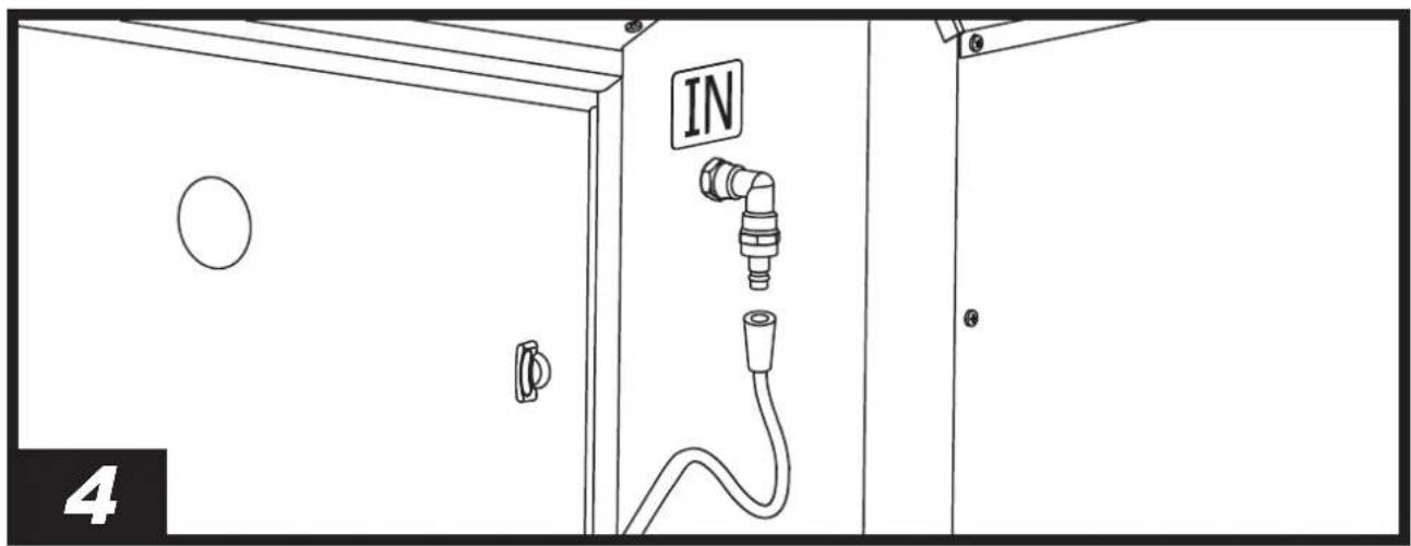
▶8.1.2. Connect the fuel pipe(s) in accordance with the correct connections (Pic. 4).
▶8.1.3. Check if there is any fuel in the tank.
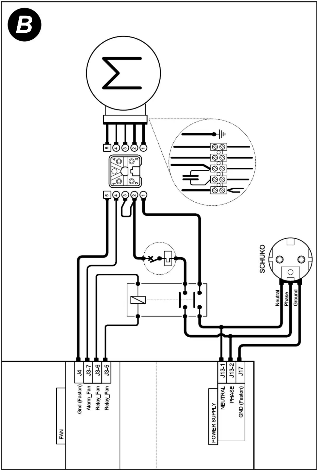
▶8.1.4. Connect the power plug to the mains (Pic. 5) (SEE VOLTAGE IN THE "TECHNICAL DATA TABLE"). The voltage presence light "I" (G Pic. 3) lights up.
▶8.1.5. HEATING MODE: Press the "HEATING ON/OFF" button (A Pic. 3) to activate the "HEATING" mode. The fan starts automatically after a few seconds. If the heater does not start, refer to paragraph "TROUBLESHOOTING". During normal operation, the heater's operating hours are shown on the display.
▶8.1.6. VENTILATION MODE: Press the "FAN ON/OFF" button (B Pic. 3) to activate the "VENTILATION ONLY" mode.
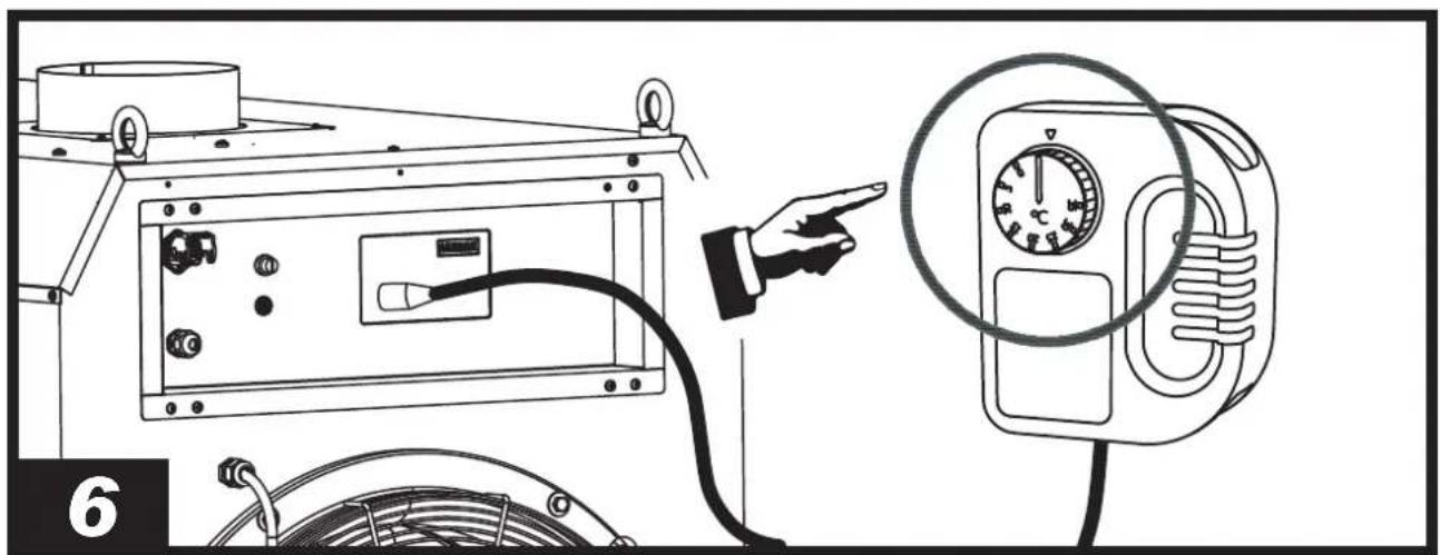
▶8.1.7. For models with a room thermostat, check the set temperature (Pic. 6).
NOTE: TO CHANGE THE MODE OF USE (VENTILATION OR HEATING), IT IS NECESSARY TO DEACTIVATE THE MODE CURRENTLY IN USE BY PRESSING THE RELEVANT "HEATING ON/OFF" OR "FAN ON/OFF" BUTTON.
NOTE: IF THE FUEL RUNS OUT, THE HEATER BLOCKS AND THE BURNER CLOCKED ALARM LIGHT LIGHTS UP ON THE CONTROL PANEL. AFTER COOLING DOWN, THE HEATER SWITCHES OFF THE FAN AND REMAINS IN ALARM. TO RESET THE HEATER (SEE PAR. "RESETTING THE HEATER").
IMPORTANT: IN INDIRECT MODELS, COMBUSTION PRODUCTS CAN BE DIRECTED OUTSIDE VIA THE DUCTS. CARRY OUT THE DUCTING IN ACCORDANCE WITH CURRENT REGULATIONS, FOLLOWING THE INSTRUCTIONS IN THE RELEVANT SECTION OF THE MANUAL.
▶▶8.2. TURNING OFF THE HEATER
▶8.2.1. HEATING MODE: Press the "HEATING ON/OFF" button (A Pic. 3) to deactivate the "HEATING" mode. The flame turns off and the fan keeps on working until the combustion chamber has fully cooled down. Do not disconnect the power plug from the mains until the cooling cycle is complete.
▶8.2.2. VENTILATION MODE: Press the "FAN ON/OFF" button (B Pic. 3) to deactivate the "VENTILATION ONLY" mode.
▶8.2.3. Wait a few minutes and then disconnect the power plug from the mains.
NOTE: THE HEATER, WITH THE POWER PLUG CONNECTED TO THE MAINS, IS ALWAYS ON STAND-BY, I.E. INACTIVE, BUT ELECTRICALLY POWERED.
▶▶▶9. RESETTING THE HEATER
In the event that a fault occurs in normal operation, the heater indicates the specific alarm on the control panel.
To reset the heater, identify and eliminate the cause that led to the alarm (for instance, lack of fuel, obstruction of the inlet
and/or outlet air vent, fan stop, etc.). If it is not possible to eliminate the problem that caused the malfunction, contact the support centre.
In order to reset the heater, we recommend following this procedure (follow all safety-related instructions):
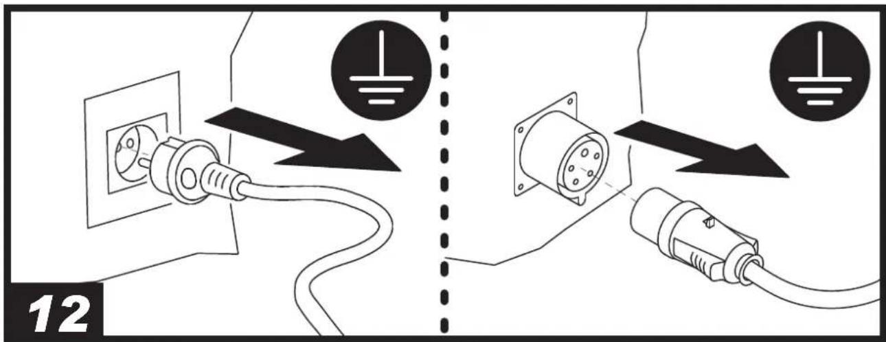
▶ BURNER VOLTAGE FAILURE RESET [Flashing light (E Pic. 3)]: No electrical voltage between burner and electronic board. Switch off the heater (A/B Pic. 3), disconnect the power supply (Pic. 12) and contact the support centre.
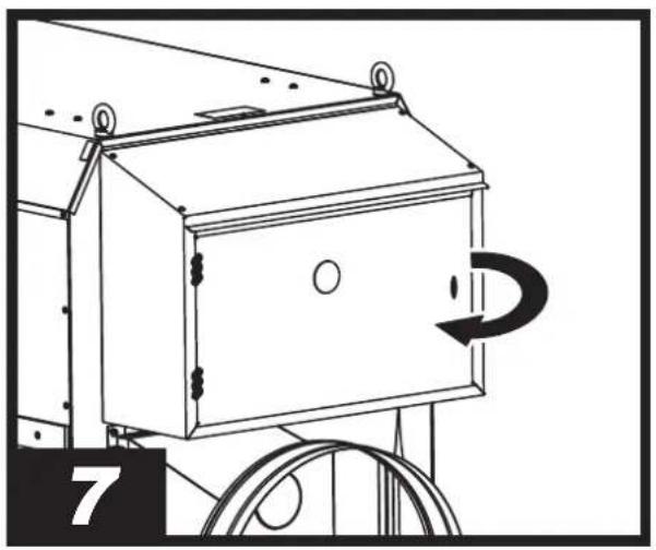
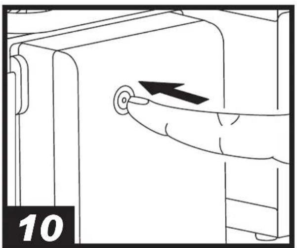
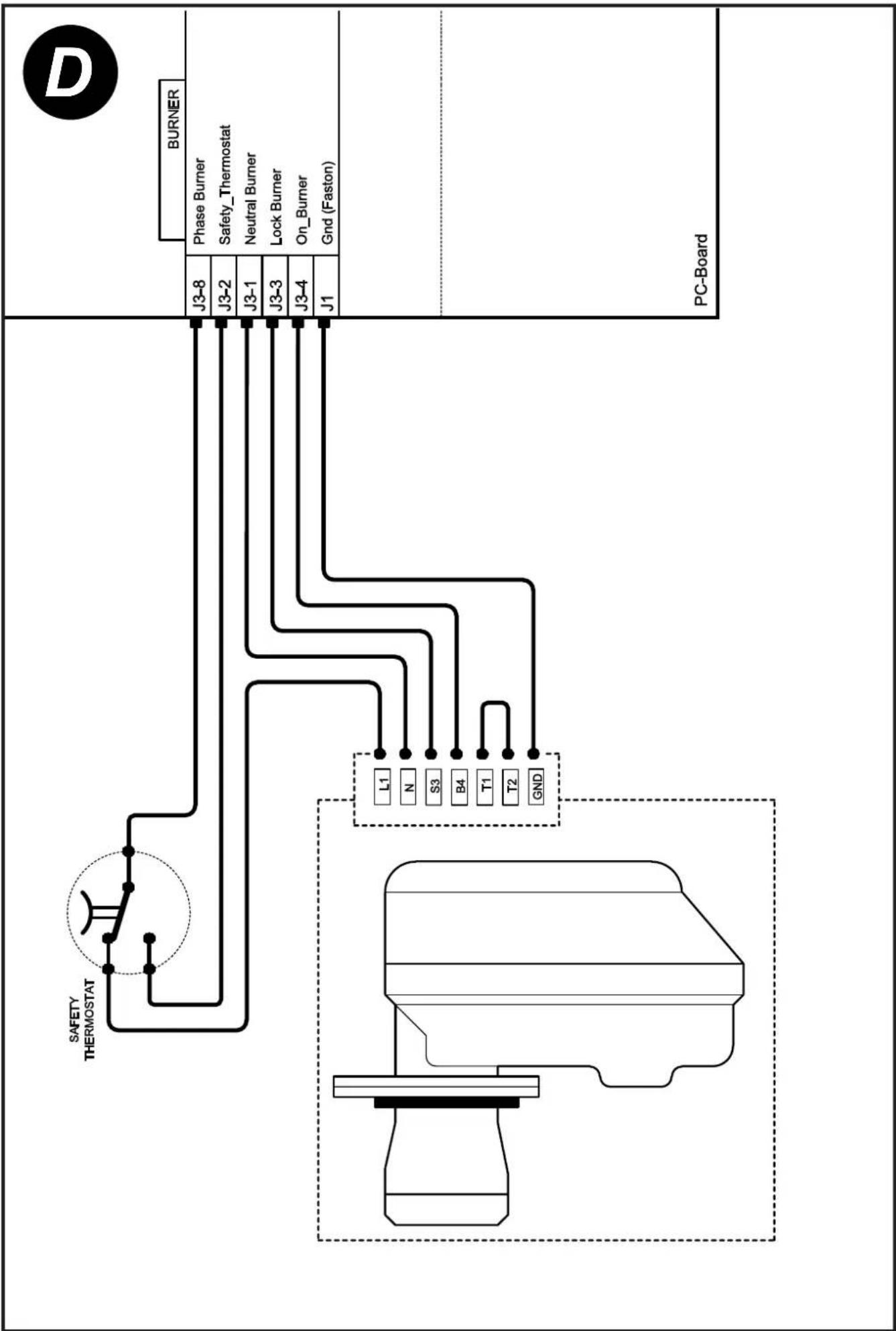
▶ BURNER RESET [Flashing light (F Pic. 3) (Pic. 9)]: The burner malfunctioned during operation. Eliminate the cause of the blockage (e.g. by topping up the fuel tank), remove the cover (Pic. 7), press the reset button (Pic. 10) fully for a few seconds and then reinstall the cover (Pic. 8). After a few unsuccessful reset attempts, the electronics will block the heater. To unlock the heater, the power supply must be disconnected (Pic. 12). If the problem persists, contact the support centre.
▶ ELECTRICAL VOLTAGE FAULT RESET [Flashing light (G Pic. 3)]: Inadequate mains voltage value. Disconnect the power supply (Pic. 12) and adapt the mains electrical system. If the problem persists, contact the support centre.
▶ OVERTEMPERATURE THERMOSTAT RESET [Flashing light (H Pic. 3)]: The heater has reached the maximum operating temperature. Eliminate the cause of the blockage, remove the cover (Pic. 7), loosen the cap, press the reset button (M Pic. 3) fully, tighten the cap back on and then reinstall the cover (Pic. 8). If the problem persists, contact the support centre.
▶ VENTILATION MOTOR RESET (depending on the model) [Flashing light (I Pic. 3)]: The ventilation motor is blocked or works abnormally. Disconnect the power supply (Pic. 12). Eliminate the cause of the blockage, remove the cover (Pic. 7), press the reset button (N Pic. 3) fully (depending on the model) and then reinstall the cover (Pic. 8). If the problem persists, contact the support centre.
▶▶▶10. CLEANING THE FILTERS
▶▶10.1. FUEL INTAKE FILTER, DEPENDING ON THE MODEL
(Pic. 11)
The filters may need to be cleaned depending on the quality of the fuel used:
▶10.1.1. Remove the cup (A).
▶10.1.2. Take out the filter (B) from the cup. Make sure you preserve the gaskets.
▶10.1.3. Clean the filter (B) with clean fuel; make sure you do not damage any components.
▶10.1.4. Put the filter (B) back into the cup.
▶10.1.5. Put the cup (A) back; make sure you reassemble the gaskets correctly.
▶▶10.2. FUEL PUMP FILTER
See the preventive maintenance schedule.
▶▶▶11. HANDLING AND STORAGE
WARNING: WHEN HANDLING THE HEATER, THE PRODUCT MUST BE SWITCHED OFF (SEE PAR. "TURNING OFF THE HEATER"), DISCONNECT THE POWER PLUG FROM THE MAINS (Pic. 12) AND WAIT FOR IT TO COOL DOWN COMPLETELY. IN ORDER TO AVOID RISKS, THE HEATER MUST BE KEPT IN A LEVEL POSITION DURING HANDLING.
In order to store the heater in the best possible conditions, we recommend following this procedure (follow all safety-related instructions):
▶12.1. It can be lifted with the forklift truck, by using suitable chains and suspension hooks (the heater is equipped with eyebolts).
▶12.2. Store the heater in a dry place and away from possible damage.
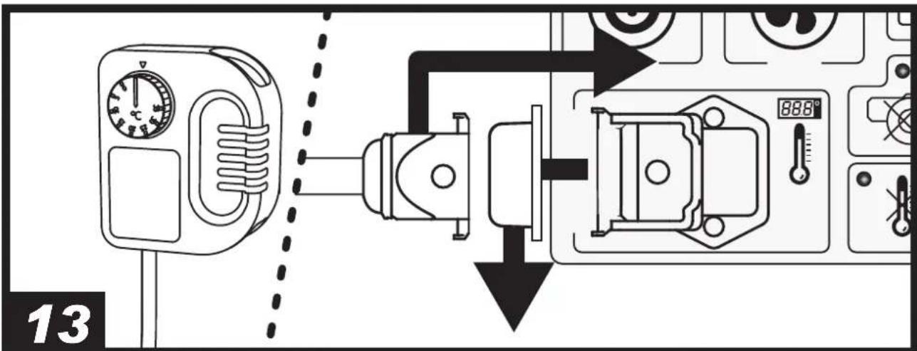
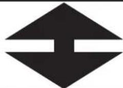
▶▶▶12. CONNECTING THE ROOM THERMOSTAT
Depending on the model, there is provision for connecting the room thermostat (D Pic. 3). For correct connection, remove the cap and connect the remote room thermostat (Pic. 13-14) to the connector (D Pic. 3), making sure to close the lock on the socket correctly. It is always advisable to secure the room thermostat cable with the tear-proof clip (P Pic. 3) in order to avoid serious damage to the control panel.
For correct operation of the heater, the cap or thermostat must always be correctly installed (Pic. 14) on the remote room thermostat connector (D Pic. 3).
▶▶▶13. TIPS FOR DUCTING
(Pic. 15)
IMPORTANT: ONLY USE ORIGINAL KITS TO DUCT THE INLET AND/OR OUTLET AIR (WHERE APPLICABLE).
In order to avoid heater operating problems or harm to people, pay attention to the layout of the air ducting pipes. In order to reduce airflow resistance, it is advisable to stretch the ducting pipes as much as possible, minimising the number of curves and avoiding bends with sharp angles. The first meters must be without curves.
▶▶▶14. PREVENTIVE MAINTENANCE SCHEDULE
| COMPONENT MA | NTENANCE FREQUENCY MAINTENANCE PROCEDURE | |
| Filters Clean or replace | once a year or as required(check integrity) | Clean the filters (SEE PAR. “CLEANING THE FILTERS”) |
| Fuel pump filter Clean or replace once a year or as required(check integrity) | Contact the support centre | |
| Electrodes Clean as required Contact the support centre | ||
| Fan Clean as required Contact the support centre | ||
| Combustion chamber Clean as required Contact the support centre | ||
▶▶▶15. TROUBLESHOOTING
| PROBLEM POSSIBLE CAUSE POSSIBLE SOLUTION | ||
| The heater does not start or does not remain on | 1. Heater in stand-by2. No power supply3. Interrupted power cable4. Electronics need to be reset or are faulty5. Incorrect setting of the room thermostat (if applicable)6. No fuel7. Foreign substances in the fuel circuit8. Temperature set on the room thermostat too high9. Electronics blocked | 1. Press the button “ON/OFF” / “VENTILATION” (A/B Pic. 3)2a. Plug the power cable correctly into the mains socket (Pic. 5)2b. Check the correct voltage of your system3. Contact the support centre4a. Reset the heater (SEE PAR. “RESETTING THE HEATER”)4b. Contact the support centre5. Set the room thermostat to a temperature higher than the temperature of the working environment (Pic. 6)6. Refuel and, if necessary, reset the heater (SEE PAR. “RESETTING THE HEATER”)7a. Empty and fill the tank with clean fuel7b. Clean the filters (SEE PAR. “CLEANING THE FILTERS”)7c. Contact the support centre8. Lower the set temperature of the room thermostat9. Reset the electronics (SEE PAR. “RESETTING THE HEATER”) |
| The heater generates smoke during operation | 1. Foreign substances in the fuel circuit2. Obstruction of inlet air vent | 1a. Empty and fill the tank with clean fuel1b. Clean the filters (SEE PAR. “CLEANING THE FILTERS”)1c. Contact the support centre2. Remove all possible obstructions from the air vent |
| The heater does not switch off | 1. Electronics are faulty 1. Contact the | support centre |
IMPORTANTE: LEGGERE E COMPRENDERE QUESTO MANUALE OPERATIVO PRIMA DI EFFETTUARE L'ASSEMBLAGGIO, LA MESSA IN FUNZIONE O LA MANUTENZIONE DI QUESTO RISCALDATORE. L'USO ERRATO DEL RISCALDATORE PUÒ CAUSARE LESIONI GRAVI O FATALI. CONSERVARE QUESTO MANUALE A TITOLO DI FUTURO RIFERIMENTO.
▶▶▶1. DESCRIZIONE
(Fig. 1)
▶▶8.1. ACCENSIONE DEL RISCALDATORE
▶▶2.2. NACHFÜLLEN DES BRENNSTOFFS
▶▶10.1. ANSAUGFILTER BRENNSTOFF, JE NACH MODELL
(Abb. 11)
▶▶▶12. ANSCHLUSS RAUMTHERMOSTAT
▶▶▶2. INFORMATIONS SUR LA SÉCURITÉ MISES EN GARDE
IMPORTANT : NE PAS UTILISER LE RÉCHAUFFEUR POUR LE CHAUFFAGE DES ZONES HABITABLES, DANS TOUS LES CAS, SE RÉFÉRER AUX DISPOSITIONS RÉGLEMENTAIRES NATIONALES.
IMPORTANT : LE RÉCHAUFFEUR D'AIR A ÉTÉ CONÇU POUR DES APPLICATIONS PROFESSIONNELLES, MOBILES ET TEMPORAIRES. IL N'EST PAS DESTINÉ À UN USAGE DOMESTIQUE, NI AU CONFORT THERMIQUE DES PERSONNES.
IMPORTANT : LE RÉCHAUFFEUR N'EST PAS ADAPTÉ POUR ÊTRE UTILISÉ PAR DES PERSONNES (Y COMPRIS LES ENFANTS) AYANT DES CAPACITÉS PHYSIQUES, SENSORIELLES OU MENTALES RÉDUITES OU PAR DES PERSONNES INEXPÉRIMENTÉES, À MOINS QU'ELLES NE SOIENT SURVEILLÉES PAR UNE PERSONNE RESPONSABLE DE LEUR SÉCURITÉ. IL CONVIENT DE SURVEILLER LES ENFANTS POUR S'ASSURER QU'ILS NE JOUENT PAS AVEC L'APPAREIL DE CHAUFFAGE.
IMPORTANT : LE FABRICANT DÉCLINE TOUTE RESPONSABILITÉ POUR LES DOMMAGES MATÉRIELS OU CORPORELS CAUSÉS PAR DES MODIFICATIONS NON AUTORISÉES APPORTÉES AU RÉCHAUFFEUR.
DANGER : L'USAGE IMPROPRE DE CE RÉCHAUFFEUR PEUT PROVOQUER DES DOMMAGES, ÊTRE UNE SOURCE DE DANGER MORTEL POUR LES PERSONNES OU IL PEUT ENTRAÎNER DES LÉSIONS, DES BRÛLURES, DES EXPLOSIONS, DES ÉLECTROCHOCS, OU L'EMPOISONNEMENT. LES PREMIERS SYMPTÔMES DE L'ASPHYXIE PAR LE MONOXYDE DE CARBONE RESSEMBLENT À CEUX DE LA GRIPPE, AVEC DES MAUX DE TÊTE, DES VERTIGES ET/OU DES NAUSÉES. CES SYMPTÔMES POURRAIENT ÊTRE CAUSÉS PAR UN FONCTIONNEMENT DÉFECTUEUX DU RÉCHAUFFEUR. SI CES SYMPTÔMES APPARAISSENT, SORTIR IMMÉDIATEMENT EN PLEIN AIR ET FAIRE RÉPARER LE RÉCHAUFFEUR PAR L'ASSISTANCE TECHNIQUE.
⚠️ DANGER : LORSQU'IL EST CONTRÔLÉ PAR UN THERMOSTAT AMBIANT (SI PRÉSENT), LE RÉCHAUFFEUR PEUT S'ALLUMER À TOUT MOMENT.
▶▶2.1. GÉNÉRALITÉS
▶▶▶11. MANUTENTION ET CONSERVATION
AVERTISSEMENT : LORS DE LA MANUTENTION DU RÉCHAUFFEUR, IL EST NÉCESSAIRE D'ÉTEINDRE LE PRODUIT (VOIR PARAG. « EXTINCTION DU RÉCHAUFFEUR »), DE DÉBRANCHER LA FICHE D'ALIMENTATION DU RÉSEAU ÉLECTRIQUE (Fig. 12) ET D'ATTENDRE LE REFROIDISSEMENT COMPLET. AFIN D'ÉVITER TOUT RISQUE, LE RÉCHAUFFEUR DOIT ÊTRE MAINTENU EN POSITION NIVELÉE LORS DE SA MANUTENTION.
▶▶▶6. WERKINGSPRINCIPES
▶▶▶11. BEHANDELING EN OPSLAG
WAARSCHUWING: WANNEER DE VERWARMER WORDT VERPLAATST, MOET HET PRODUCT WORDEN UITGESCHAKELD (ZIE HOOFDSTUK "UITSCHAKELEN VAN DE VERWARMER"), DE STEKKER UIT HET STOPCONTACT WORDEN GETROKKEN (Fig. 12) EN GEWACHT WORDEN TOT DE VERWARMER VOLLEDIG IS AFGEKOELD. OM RISICO'S TE VERMIJDEN, MOET DE VERWARMER TIJDENS HET VERPLAATSEN IN EEN VLAKKE STAND WORDEN GEHOUDEN.
▶▶▶12. AANSLUITING OMGEVINGSTHERMOSTAAT
▶▶▶15. EEN PROBLEEM OPSPOREN
TEMMELSER SKAL ALTID OVERHOLDES.

VIGTIGT: VARMLUFTAPPARATET ER DESIGNET
PROFESSIONELLE, MOBILE OG MIDLERTIDIGE
ENDELSER. DET ER IKKE BEREGNET TIL
HOLDNINGSBRUG ELLER TIL PERSONERS
MEKOMFORT.

VIGTIGT: VARMEAPPARATET MÅ IKKE BRUGES AF
SONER (HERUNDER B∅RN) MED NEDSATTE FYSISKE,
SORISKE ELLER MENTALE EVNER ELLER AF
SONER, SOM MANGLER ERFARING OG KENDSKAB,
MINDRE DE ER INSTRUERET I BRUG AF APPARATET
EN PERSON, DER ER ANSVARLIG FOR DERES
ERHED. B∅RN SKAL OVERVÅGES FOR AT SIKRE, AT
KE LEGER MED VARMEAPPARATET.

VIGTIGT: PRODUCENTEN ER IKKE ANSVARLIG
PERSON- OG TINGSKADE, DER MÅTTE OPSTÅ
F∅LGE AF BRUGERENS MANGLENDE VIDEN OM
MEAPPARATET.

FARE: FORKERT BRUG AF VARMEAPPARATET
MEDF∅RE PERSONSKADE ELLER LIVSFARE,
STELSER, FORBRÆNDINGER, EKSPLOSION,
TROCHOK ELLER FORGIFTNING. DE F∅RSTE
N PÅ ILTMANGEL SOM F∅LGE AF INDÅNDING AF
LTEDAMPE LIGNER SYMPTOMERNE PÅ INFLUENZA,
HOVEDPINE, SVIMMELHED OG/ELLER KVALME.
E SYMPTOMER KAN VÆRE FORÅRSAGET AF
KERT DRIFT AF VARMEAPPARATET. SKULLE
E SYMPTOMER OPSTÅ, SKAL DU STRAKS GÅ
NFOR, OG FÅ VARMEAPPARATET REPARERET AF
VICEAFDELINGEN.

FARE: VARMEAPPARATET KAN, NÅR DET STYRES AF
A. ON/OFF KNAP FOR OPVARMNING: ON/OFF-knappen for "OPVARMNING"-tilstand.
B. ON/OFF KNAP FOR BLÆSER: ON/OFF-knap til kun "VENTILATION"-tilstand.
C. Display.
D. Fjernbetjent rumtermostat-stik (rumtermostat ekstraudstyr).
▶▶▶3. PAKKAUKSEN PURKAMINEN
VAROITUS: PAKKAUSMATERIAALI EI OLE LASTEN LEIKKIKALU. SÄILYTÄ MUOVIPUSSIA LASTEN ULOTTUMATTOMISSA; AIHEUTTAA TUKEHTUMISVAARANI
▶▶▶12. TILKOBLING AV ROMTERMOSTAT
▶▶▶14. PROGRAM FOR FOREBYGGENDE VEDLIKEHOLD
▶▶8.1. WŁĄCZENIE NAGRZEWNICY
▶▶▶9. RESET NAGRZEWNICY
▶▶▶15. OKREŚLANIE PROBLEMU
▶▶▶13. INDIKACE PRO POTRUBÍ
(Obr. 15)
DÜLEŽITÉ: VYHNĚTE SE USMĚRŇOVÁNÍ VZDUCHU NA VSTUPU A/NEBO VÝSTUPU JINAK, NEŽ S POUŽITÍM ORIGINÁLNÍCH SAD (V PŘÍPADĚ POTŘEBY).
▶▶▶15. PROBLEMİN SAPTANMASI
▶▶▶14. ENNETAVA HOOLDUSE PROGRAMM
▶▶▶15. PROBLEEMI TUVASTAMINE
▶▶8.1. ANAΦΛΕΞΗ TOY ΘΕΡΜΑΝΤΗΡΑ
natural_image
Diagram of a helicopter with propellers and wheels, no text or symbols present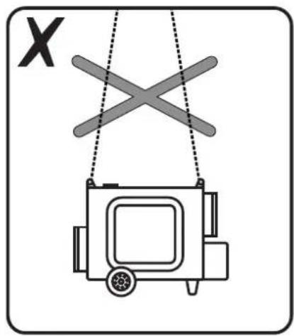
natural_image
Simple line drawing of a device suspended by two ropes with X marks, no text or symbols present.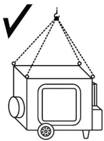
natural_image
Simple line drawing of a box with wheels and a handle, no text or symbols present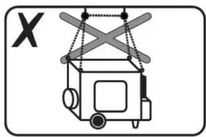
natural_image
Simple line drawing of a crane lifting a box with no text or symbols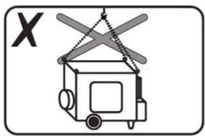
natural_image
Simple line drawing of a box with a handle and a cross mark, no text or symbols present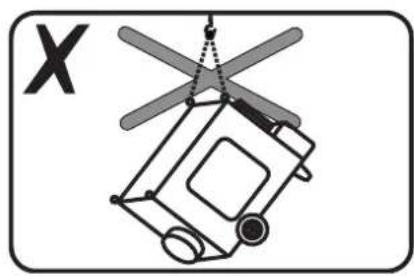
natural_image
Diagram of a helicopter with a triangular roof and attached rotor, labeled 'X' (no text or symbols on the diagram itself)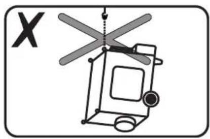
natural_image
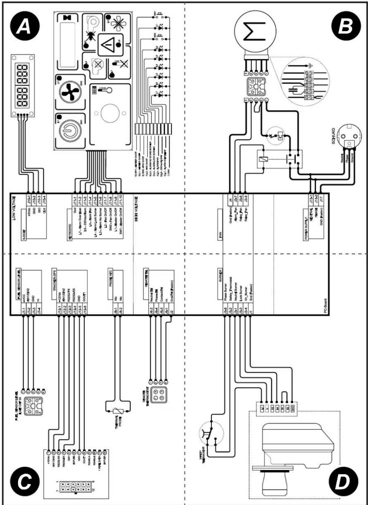
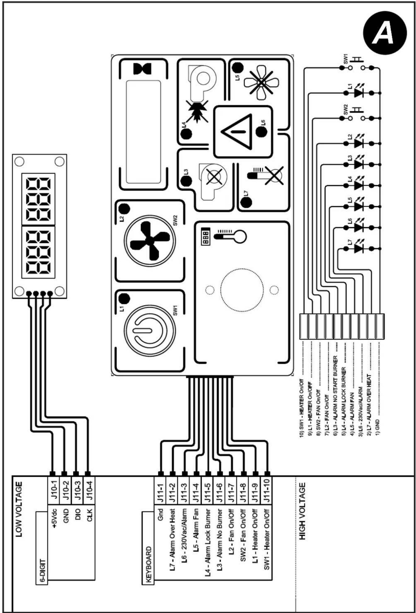
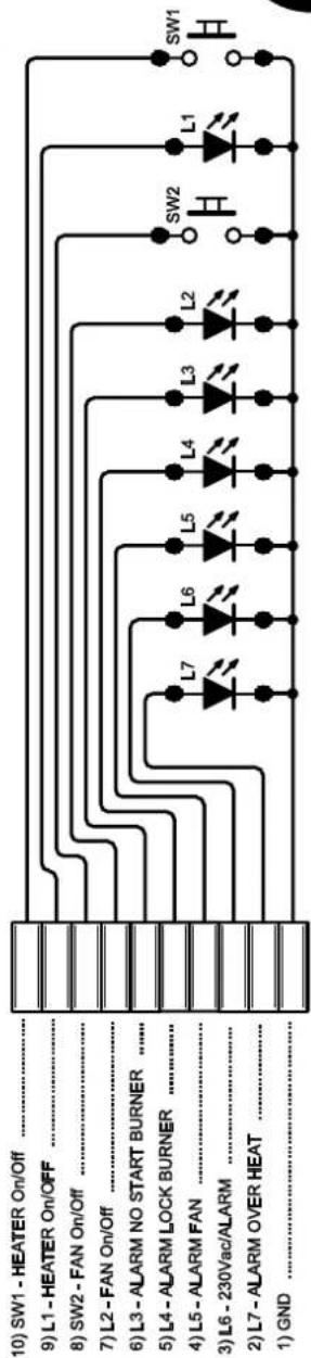
Diagram of a helicopter with X-axis indicators and no readable text or symbolsWIRING DIAGRAMS - SCHEMI ELETTRICI - SCHALTPLÄNE - ESQUEMAS ELÉCTRICOS - SCHEMAS ELECTRIQUES - ELEKTRISCHE SCHEMA'S - ESQUEMAS ELÉCTRICOS - ELEKTRISKE SKEMAER - SÄHKÖKAAVIOT - KOPLINGSSKJEMA - ELEKTRISKA KOPPLINGSSCHEMAN - SCHEMATY ELEKTRYCZNE - ЭЛЕКТРИЧЕСКИЕ СХЕМЫ - ELEKTRICKÁ SCHÉMATA - VILLANYBEKÖTÉSI RAJZOK - ELEKTRIČNE SHEME - ELEKTRÍM ALARI - ELEKTRIČNE SHEME - ELEKTROS SCHEMOS - ELEKTRISKÄS SHÉMAS - ELEKTRISKEEMID - SCHEME ELECTRICE - ELEKTRICKÉ SCHÉMY - ЕЛЕК- ТРИЧЕСКИ СХЕМИ - ЕЛЕКТРИЧНІ СХЕМИ - ELEKTRIČNE ŠEME - НЛЕКТРІКА ΣΧΕΔΙΑ - 线路图 - ЭЛЕКТРЛІ СУЛБЕЛЕР
flowchart
graph TD
    A["High Voltage"] --> B["10 SWI - HEATER ON/OFF"]
    A --> C["9 L1-HEATER ON/OFF"]
    A --> D["8 SW2-FAN ON/OFF"]
    A --> E["7 L2-FAN ON/OFF"]
    A --> F["6 L3-ALAM NO START SURNER"]
    A --> G["5 L4-ALAM LOCK SURNER"]
    A --> H["4 L5-ALAM FAN"]
    A --> I["2 L7-ALAM OVER HEAT"]
    A --> J["1) GND"]
    K["Low Voltage"] --> L["+5VDC 10^-1"]
    K --> M["GDN 10^-2"]
    K --> N["CILK 10^-3"]
    K --> O["IO 10^-3"]
    K --> P["CLK 10^-4"]
    K --> Q["CLK 10^-4"]
    R["KeyBOARD"] --> S["11-1.1"]
    R --> T["17-Arm Over Heat 11-2"]
    R --> U["11-6"]
    R --> V["11-5"]
    R --> W["11-7"]
    R --> X["11-8"]
    R --> Y["L1-Heater ON/OFF 11-9"]
    R --> Z["SW2-Fan ON/OFF 11-8"]
    R --> AA["L2-Fan ON/OFF 11-7"]
    R --> AB["L3-Alarm No Burner 11-6"]
    R --> AC["SW1 - Heater ON/OFF 11-10"]
    R --> AD["L4-Alarm Lock Burner 11-5"]
    R --> AE["LS-Alarm Fan 11-4"]
    R --> AF["L5-Alarm ALAM 11-3"]
    R --> AG["12"] BBB
    R --> AH[SW2 SW2 SW2 SW2 SW2 SW2 SW2 SW2 SW2 SW2 SW2 SW2 SW2 SW2 SW2 SW2 SW2 SW2 SW2 SW2 SW2 SW2 SW2 SW2 SW2 SW2 SW2 SW2 SW2 SW2 SW2 SW2 SW2 SW2 SW2 SW2 SW2 SW2 SW2 SW2 SW2 SW2 SW2 SW2 SW2 SW2 SW2 SW2 SW2 SW2 SW2 Sw2 SW2 SW2 SW2 SW2 SW2 SW2 SW2 SW2 SW2 SW2 SW2 SW2 SW2 SW2 SW2 SW2 SW2 SW2 SW2 SW2 SW2 SW2 SW2 SW2 SW2 SW2 SW2 SW2 SW2 SW2 SW2 SW2 SW2 SW2 SW2 SW2 SW2 SW2 SW2 SW2 SW2 SW2 SW2 SW2 SW2 SW2 SW2 SW2 SW2 SBW
    style A fill:#f9f,stroke:#333
    style K fill:#ccf,stroke:#333
    style R fill:#cfc,stroke:#333
    style S fill:#fcc,stroke:#333
    style T fill:#fcc,stroke:#333
    style U fill:#fcc,stroke:#333
    style V fill:#fcc,stroke:#333
    style W fill:#fcc,stroke:#333
    style X fill:#fcc,stroke:#333
    style Y fill:#fcc,stroke:#333
    style Z fill:#fcc,stroke:#333
    style AA fill:#fcc,stroke:#333
    style AB fill:#fcc,stroke:#333
    style AC fill:#fcc,stroke:#333
    style AD fill:#fcc,stroke:#333
    style AE fill:#fcc,stroke:#333
    style AF fill:#fcc,stroke:#333
    style AG fill:#fcc,stroke:#333
    style AH fill:#fcc,stroke:#333
    style AI fill:#fcc,stroke:#333
    style AJ fill:#fcc,stroke:#333
    style AK fill:#fcc,stroke:#333
    style AL fill:#fcc,stroke:#333
    style AM fill:#fcc,stroke:#333
    style AN fill:#fcc,stroke:#333
    style AO fill:#fcc,stroke:#333
    style AP fill:#fcc,stroke:#333
    style AQ fill:#fcc,stroke:#333
    style AR fill:#fcc,stroke:#333
    style AS fill:#fcc,stroke:#333
    style AT fill:#fcc,stroke:#333
    style AU fill:#fcc,stroke:#333
    style AV fill:#fcc,stroke:#333
    style AW fill:#fcc,stroke:#333
flowchart
graph TD
    A["SWI"] --> B["Diode L1"]
    C["SW2"] --> D["Diode L2"]
    E["Diode L3"] --> F["Diode L4"]
    G["Diode L5"] --> H["Diode L6"]
    I["Diode L7"] --> J["Diode L8"]
    K["Diode L9"] --> L["Diode L10"]
    M["Diode L11"] --> N["Diode L12"]
    O["Diode L13"] --> P["Diode L14"]
    Q["Diode L15"] --> R["Diode L16"]
    S["Diode L17"] --> T["Diode L18"]
    U["Diode L19"] --> V["Diode L20"]
    W["Diode L21"] --> X["Diode L22"]
    Y["Diode L23"] --> Z["Diode L24"]
    AA["Diode L25"] --> AB["Diode L26"]
    AC["Diode L27"] --> AD["Diode L28"]
    AE["Diode L29"] --> AF["Diode L30"]
    AG["Diode L31"] --> AH["Diode L32"]
    AI["Diode L33"] --> AJ["Diode L34"]
    AK["Diode L35"] --> AL["Diode L36"]
    AM["Diode L37"] --> AN["Diode L38"]
    AO["Diode L39"] --> AP["Diode L40"]
    AQ["Diode L41"] --> AR["Diode L42"]
    AS["Diode L43"] --> AT["Diode L44"]
    AU["Diode L45"] --> AV["Diode L46"]
    AW["Diode L47"] --> AX["Diode L48"]
    AY["SWI - HEATER ON/OFF"] --> AZ["10) SWI - HEATER ON/OFF"]
    BA["SWI + HEATER ON/OFF"] --> BB["9) L1 - HEATER ON/OFF"]
    BC["SWI + HEATER ON/OFF"] --> BD["8) SW2 - PAN ON/OFF"]
    BE["SWI + HEATER ON/OFF"] --> BF["7) L2 - PAN ON/OFF"]
    BG["SWI + HEATER ON/OFF"] --> BH["6) L3 - ALARM NO START BURNER"]
    BI["SWI + HEATER ON/OFF"] --> BJ["5) L4 - ALARM LOCK BURNER"]
    BK["SWI + HEATER ON/OFF"] --> BL["4) L5 - ALARM PAN"]
    BM["SWI + HEATER ON/OFF"] --> BN["3) L6 - 230VAC/ALARM"]
    BO["SWI + HEATER ON/OFF"] --> BP["2) L7 - ALARM OVER HEAT"]
    BQ["SWI + HEATER ON/OFF"] --> BR["1) AND"]
flowchart
graph TD
    A["Power Supply"] --> B["Switch"]
    B --> C["RLay Fan 13-5"]
    B --> D["RLay Fan 13-6"]
    B --> E["RLay Fan 13-7"]
    B --> F["RLay Fan 14"]
    B --> G["Amn Fan 13-7"]
    B --> H["Amn Fan 14"]
    B --> I["Ground"]
    B --> J["Phase"]
    B --> K["Neutral"]
    B --> L["Neural"]
    style A fill:#f9f,stroke:#333
    style B fill:#ccf,stroke:#333
    style C fill:#cfc,stroke:#333
    style D fill:#cfc,stroke:#333
    style E fill:#cfc,stroke:#333
    style F fill:#cfc,stroke:#333
    style G fill:#cfc,stroke:#333
    style H fill:#cfc,stroke:#333
    style I fill:#cfc,stroke:#333
    style J fill:#cfc,stroke:#333
    style K fill:#cfc,stroke:#333
    style L fill:#cfc,stroke:#333
    style M fill:#fff,stroke:#000
    style N fill:#fff,stroke:#000
    style O fill:#fff,stroke:#000
    style P fill:#fff,stroke:#000
    style Q fill:#fff,stroke:#000
    style R fill:#fff,stroke:#000
    style S fill:#fff,stroke:#000
    style T fill:#fff,stroke:#000
    style U fill:#fff,stroke:#000
    style V fill:#fff,stroke:#000
    style W fill:#fff,stroke:#000
    style X fill:#fff,stroke:#000
    style Y fill:#fff,stroke:#000
    style Z fill:#fff,stroke:#000

flowchart
graph TD
    A["FUEL SENSOR LEVEL"] --> B["TRACKER-GPS"]
    A --> C["PROBE NTC"]
    A --> D["Remote Control"]
    A --> E["Remote Control"]
    A --> F["FUEL SENSOR LEVEL"]
    B --> G["12-6"]
    C --> H["18-2"]
    D --> I["12-6"]
    E --> J["12-6"]
    F --> K["12-6"]
    G --> L["17-4"]
    H --> M["12-6"]
    I --> N["12-6"]
    J --> O["12-6"]
    K --> P["12-6"]
    L --> Q["17-4"]
    M --> R["12-6"]
    N --> S["12-6"]
    O --> T["17-4"]
    P --> U["12-6"]
    Q --> V["12-6"]
    R --> W["17-4"]
    S --> X["12-6"]
    T --> Y["17-4"]
    U --> Z["12-6"]
    V --> AA["17-4"]
    W --> AB["12-6"]
    X --> AC["17-4"]
    Y --> AD["12-6"]
    Z --> AE["17-4"]
    AA --> AF["17-4"]
    AB --> AG["12-6"]
    AC --> AH["17-4"]
    AD --> AI["12-6"]
    AE --> AJ["17-4"]
    AF --> AK["17-4"]
    AG --> AL["12-6"]
    AH --> AM["17-4"]
    AI --> AN["17-4"]
    AJ --> AO["17-4"]
    AK --> AP["17-4"]
    AL --> AQ["17-4"]
    AM --> AR["17-4"]
    AN --> AS["17-4"]
    AO --> AT["17-4"]
    AP --> AU["17-4"]
    AQ --> AV["17-4"]
    AR --> AW["17-4"]
    AS --> AX["17-4"]
    AT --> AY["12-6"]
    AU --> AZ["17-4"]
    AV --> BA["17-4"]
    AW --> BB["17-4"]
flowchart
graph TD
    A["PC-Board"] --> B["Heater"]
    B --> C["Safety Monitoring Unit"]
    C --> D["BURNER"]
    C --> E["Phase Burner"]
    C --> F["Safety-Thermostel"]
    C --> G["Neutral Burner"]
    C --> H["Lock Burner"]
    C --> I["On-Burner"]
    C --> J["13-4"]
    C --> K["13-3"]
    C --> L["13-1"]
    C --> M["13-8"]
    C --> N["1"]
    C --> O["23-4"]
    C --> P["23-3"]
    C --> Q["23-1"]
    C --> R["23-2"]
    C --> S["23-8"]
CE CONFORMITY CERTIFICATE
CE
CE CONFORMITY CERTIFICATE - DICHIARAZIONE DI CONFORMITÀ CE - EG-KON-FORMITÄTSERKLÄRUNG - DECLARACIÓN DE CONFORMIDAD CE - DECLARATION DE CONFORMITE CE - EG-CONFORMITEITVERKLARING - DECLARAÇÃO DE CONFORMIDA-DE CE - EU-OVERENSSTEMMELSESERKLÆRING - EY-VAATIMUSTENMUKAISUUSVA-KUUTUS - CE-SAMSVARSERKLÆRING - EG-FÖRSÄKRAN OM ÖVERENSSTÄMMELSE - DEKLARACJA ZGODNOŚCI WE - ДЕКЛАРАЦИЯ О COOTBETCTВИИ CE - PROHLÁŠENÍ O SHODĚ CE - EK MEGFELELŐSÉGI NYILATKOZAT - IZJAVA O SKLADNOSTI IN OZNAKA CE - CE UYGUNLUK BEYANI - IZJAVA CE O SUKLADNOSTI - ES ATITIKTIES DEKLARACIJA - EK ATBILSTĪBAS - DEKLARĀCIJA - EÜ VASTAVUSDEKLARATSIOON - DECLARATIE DE CONFORMITATE CE - PREHLÁSENIE O ZHODE CE - ДЕКЛАРАЦИЯ ЗА СЪВМЕСТИМОСТ CE - ДЕКЛАРАЦІЯ ВІДПОВІДНОСТИ CE - IZJAVA CE O PRIKLADNOSTI ΔΗΛΩΣΗ ΣΥΜΜΟΡΦΩΣΗΣ CE - CE 符合性声明
DANTHERM GROUP S.p.A. Via Gardesana 11, -37010- Pastrengo (VR), ITALY
Product: - Prodotto: - Produkt: - Producto: - Produit: - Product: - Produkt: - Tuote: - Produkt: - Produkt: - Produkt: - Изделие: - Výrobek: - Termék: - Izdelek: - Ürün: - Proizvod: - Gaminys: - Ierīce: - Toode: - Produsul: - Výrobok: - Продукт: - Виріб: - Proizvod: - Проїóv: - 产品:
K 120 - K 160
We declare that it is compliant with: - Si dichiara che è conforme a: - Es wird als konform mit den folgenden Normen erklärt: - Se declara que está en conformidad con: - Nous déclarons sa conformité à: - Hierbij wordt verklaard dat het product conform is met: - Declara-se que está em conformidade com: - Vi erklærer at produktet er i overensstemmelse med: - Vakuutetaan olevan yhdenmukainen: - Man erklærer at apparatet er i overensstemmelse med: - Härmed intygas det att produkten är förenlig med följande: - Oświadczca się, że jest zgodny z: - Заявляем о соответствии требованиям: - Prohlašuje se, že je v souladu s: - Kijelentjük, hogy a termék megfelel az alábbiaknak: - Izpolnjuje zahteve: - Aşağıdaki standartlara uygun olduğunu beyan ederiz: - Izjavljuje se da je u skladu s: - Pareiškiame, kad atitinka: - Tiek deklarēts, ka atbilst: - Käesolevaga deklareeritakse, et toode vastab: - Declarăm că este conform următoarelor: - Prehlasuje sa, že je v súlade s: - Декларира се че отговаря на: - Відповідає вимогам: - Izjavljuje se da je u skladu s: - Δηλώνουμε ότι είναι σύμφωνο με: - 兹证明符合:
2014/30/EU, 2014/35/EU
EN 62233:2008, EN 61000-3-2:2014, EN 61000-3-3:2013, EN 55014-1:2006/A2:2011, EN 55014-2:2015, EN 60335-1:2012/A11:2014, EN 60335-2-102:2016

natural_image
Abstract blue line drawing with no text or symbolsPastrengo, 2024
▶ en - DISPOSAL OF THE PRODUCT
-This product has been designed and manufactured with top-quality materials and components, which can be re-cycled and re-used. -When a crossed-wheely bin symbol is attached to the product, it means that the product is protected by the, 2012/19/UE European Directive.
-Please obtain information regarding the local differentiated collection system for electrical and electronic products.
-Respect local Standards in force and do not dispose of old products as normal domestic waste. Correct disposal of the product helps to prevent possible negative consequences for health, the environment and mankind.
▶pl - UTYLIZACJA PRODUKTU
▶ Iv - PRODUKTA IZNÍCINÁŠANA
natural_image
Abstract geometric composition with yellow and black blocks (no text or symbols)Dantherm Group S.p.A.
Via Gardesana 11
37010 Pastrengo (VR)
Italy
t.: +39 045 6770533
e.: info.it@danthermgroup.com

DOWNLOAD CATALOGUE

SEND US YOUR FEEDBACK

REGISTER FOR 3-YEARWARRANTEE