
K 120 R - Heating Heylo - Free user manual and instructions
Find the device manual for free K 120 R Heylo in PDF.


| Product Type | Portable Heater |
| Brand | Heylo |
| Model | K 120 R |
| Dimensions (HxWxD) | Approx. 45 x 30 x 28 cm |
| Weight | Approx. 8 kg |
| Power Supply | 230 V, 50 Hz |
| Power Rating | 1500 - 2000 W |
| Heating Type | Electric fan heater |
| Temperature Control | Adjustable thermostat |
| Fan Speeds | 2 or 3 speeds |
| Air Flow | Up to 150 m³/h |
| Noise Level | Approx. 45 dB(A) |
| Safety Features | Tip-over switch, overheat protection, thermal fuse |
| Housing Material | Steel with powder coating |
| Protection Class | IP20 |
| Certification | CE, GS mark |
| Maintenance | Clean air filter monthly; ensure ventilation grilles clear |
| Repair & Spare Parts | Replaceable fan motor, heating element, thermostat available |
| Warranty | 2 years |
Frequently Asked Questions - K 120 R Heylo
User questions about K 120 R Heylo
0 question about this device. Answer the ones you know or ask your own.
Ask a new question about this device
Download the instructions for your Heating in PDF format for free! Find your manual K 120 R - Heylo and take your electronic device back in hand. On this page are published all the documents necessary for the use of your device. K 120 R by Heylo.
USER MANUAL K 120 R Heylo
Translation of the original instruction manual

natural_image
Exterior view of a Heylo industrial gasifier with orange and gray casing (no visible text or symbols beyond branding)DE Ölheizer K 120 (R) / K 160 (R)
EN Oil heater K 120 (R) / K 160 (R)
www.heylo.de
Version 12/2023
Art.-Nr./item no.
Dantherm GmbH
Oststraße 148
DE-22844 Norderstedt
Tel.: +49 (0) 40-5268790
Info.de@danthermgroup.com
http://www.danthermgroup.com
Schutzvermerk
natural_image
Diagram of a yellow forklift transporting a shipping container, with an inset showing a side view of a container being lifted (no text or symbols present)natural_image
Red circular connector with three pins and a labeled section (no text or symbols beyond label)natural_image
Interior view of an electrical enclosure with labeled components (no readable text or symbols)flowchart
graph TD
    A["Thermal Control System"] --> B["Thermal Control Unit"]
    B --> C["Thermal Control Bus"]
    C --> D["Thermal Control Bus to Heating"]
    D --> E["Thermal Control Bus to Heating to Cooling"]
    E --> F["Thermal Control Bus to Heating to Cooling"]
    F --> G["Thermal Control Bus to Heating to Cooling"]
    G --> H["Thermal Control Bus to Heating to Cooling"]
    H --> I["Thermal Control Bus to Heating to Cooling"]
    I --> J["Thermal Control Bus to Heating to Cooling"]
    J --> K["Thermal Control Bus to Heating to Cooling"]
    K --> L["Thermal Control Bus to Heating to Cooling"]
    L --> M["Thermal Control Bus to Heating to Cooling"]
    M --> N["Thermal Control Bus to Heating to Cooling"]
    N --> O["Thermal Control Bus to Heating to Cooling"]
    O --> P["Thermal Control Bus to Heating to Cooling"]
    P --> Q["Thermal Control Bus to Heating to Cooling"]
    Q --> R["Thermal Control Bus to Heating to Cooling"]
    R --> S["Thermal Control Bus to Heating to Cooling"]
    S --> T["Thermal Control Bus to Heating to Cooling"]
    T --> U["Thermal Control Bus to Heating to Cooling"]
    U --> V["Thermal Control Bus to Heating to Cooling"]
    V --> W["Thermal Control Bus to Heating to Cooling"]
Table of contents
13 About this operating manual 46
13.1 The purpose of this manual. ---- 46
13.2 Keep the manual safe and at hand at all times 46
13.3 Symbols and definitions used ---- 46
13.4 Warranty 47
13.5 Contacting DANTHERM GmbH ---- 48
14 Safety 48
14.1 Information on electrical equipment ---- 49
14.2 Notes on fire protection 50
14.3 Requirements for heating oil supply ---- 50
14.4 Notes on environmental protection ---- 51
14.5 Operating conditions 51
14.6 Personal protective equipment ---- 52
14.7 Residual hazards 53
15 Product description 53
15.1 Identification of the machine ---- 53
15.2 General description 53
15.2.1 Intended use 55
15.2.2 Improper use 55
15.2.3 Foreseeable misuses ---- 55
15.3 Device components---- 55
15.3.1 Burners 55
15.3.2 Fan 56
15.3.3 Controls 56
15.3.4 Safety devices 56
15.4 Operating and display elements ---- 57
16 Transport and installation 58
16.1 Transport by forklift truck 59
16.2 Transport by crane 60
16.3 Assembly and connection 60
17 Commissioning 62
18 Operation 63
18.1 The sequences for switching on and off -- 63
18.2 Operating modes 64
18.3 Operating the external ambient temperature regulator 64
19 Malfunctions 65
19.1 Restarting after an unscheduled downtime 65
19.2 Malfunctions during operation ---- 66
20 Cleaning and maintenance 70
20.1 Cleaning the device 71
20.2 Burner maintenance 72
20.2.1 Replacing oil filter 73
20.2.2 Replacing oil nozzle 73
20.2.3 Setting the burner 74
20.2.4 Exhaust gas analysis 74
20.3 Maintenance schedule 76
20.4 Wear and spare parts 76
20.5 Customer service by the manufacturer --- 76
21 Repairs 77
22 Decommissioning, storage and disposal --- 77
22.1 Decommissioning 77
22.2 Storing the device 77
22.3 Disposal 77
23 Technical details 78
24 Supplementary documents 79
24.1 List of wear and spare parts 79
24.2 Accessories 83
24.3 Declaration of conformity---- 83
24.4 Circuit diagram 84
13 About this operating manual
This operating manual (hereinafter referred to as the manual) enables the operating company to work safely with the oil-heated hot air heater (hereinafter referred to as the device) of type K 120, K 120 R, K 160 and K 160 R. It describes the device manufactured by Dantherm GmbH (hereinafter referred to as HEYLO).
- Please read the manual carefully.
– Follow all the safety instructions.

NOTICE
Sample illustrations
The four different oil heaters differ only in the details mentioned above. For illustration purposes, illustrations of the K 120 device type are used as examples in this manual. Differences between the devices will be pointed out separately if necessary.
13.1 The purpose of this manual.
The manual serves the company operating the device and all the staff who use it as a guide and reference book on the operation and technical aspects of the device.
The technical data on settings, maintenance and the electrical features have been prepared for specialists who are specially authorized for these areas of responsibility. Unauthorized persons may not carry out the work specified here.
An oil burner tested according to DIN EN 267 is installed. This operating manual for the device is always supplemented by the burner manufacturer's operating manual for the burner.
13.2 Keep the manual safe and at hand at all times
The manual must always be kept where the machine is located. The company operating the device must make the instructions available to the technical staff and all the operators of the device throughout the service life of the device.
13.3 Symbols and definitions used
This section explains the symbols used in this manual.
Instructions
The safety instructions in this manual contain the following elements:

DANGER
Warning indicating an immediate danger for people
This safety instruction warns of an immediate dangerous situation which can lead to serious injury or death.

WARNING
Warning indicating a potential danger for people.
This safety instruction warns of a potentially hazardous situation which, if not avoided, could result in death or serious injury.

CAUTION
Warning indicating a potential danger for people.
This safety instruction warns of a potentially hazardous situation which, if not avoided, could result in minor to moderate injury.

Attention
Warning of possible damage to property.
This safety instruction warns of damage to machinery.
A safety instruction consists of (in addition to the symbol and the signal word):
- Signal word
- Type and source of hazard
- Effects
- Escape (= measures to escape from the danger)
Example

DANGER
Electric shock due to high voltage (type and source of danger)
Death from electric shock! (effects)
a) Wait four minutes before starting work on the motor connections! (measures)
Important or helpful instructions, information and tips have the following structure:

NOTICE
Information
User tips and useful information that help you to make optimal use of the device's functions are listed below this symbol.
Mandatory symbols
The manual uses the following mandatory symbols.
Symbol Meaning

General instruction
This symbol indicates instructions and may signal prohibitions.
Tab. 12: Mandatory symbols
Markings in the text
- Listings are indicated by an indent mark (-).
- Text marked in this way highlights references and hyperlinks referring to related topics, internet addresses, and other information.
- Text highlighted in bold indicates highlighting or subheadings.
- Menu items, tabs, buttons and Softkey buttons are set in angled brackets <...>, e.g.
. - Sequences are enclosed in angle brackets <...>, e.g.
. - Buttons or indicator lights on a keyboard or control panel are enclosed in square brackets, e.g. [Start].
- Text highlighted in this way SPS indicates a cross-reference to the glossary with an explanation of terms.
Action instructions
As a rule, action instructions have the following structure:
√ Conditions that are necessary in order for the action to be carried out may also be referred to here.
a) These are followed by operating steps
b) Another operating step
→ Partial result after one operating step
c) Another operating step
→ Overall result of an action instruction
13.4 Warranty
In general, the "General Terms and Conditions of Sale and Delivery" of DANTHERM GmbH shall apply. The prerequisite for claiming the statutory liability for material defects within the first two years (1 year for commercial use) from the date of purchase is the intended use. Wear parts (oil nozzle, oil filter) are excluded from the warranty.
13.5 Contacting Dantherm GmbH
If you have any questions about the device, please get in touch with your sales partner.
We will also gladly provide information ourselves. Please get in touch with one of our contacts listed below or visit us on the Internet, providing the following information:
- Your name and address,
- Contact person at your company,
- The data on the rating plate. Type, serial No. and year of construction.
Tab. 13: Registered office
14 Safety
This device has been built using state-of-the-art technology and the following recognized safety and technical regulations. Nonetheless, danger to the life and limb of the operator or third parties may arise if it is not used properly. Similarly, the device or other property and material may become damaged.
The device must only be used:
- For the purpose for which it was intended
- And when it is in a perfect technical condition.
The device must not be restarted until any fault that may impair safety has been rectified.
Any persons installing, operating, maintaining or cleaning the device must be aware of the hazards that may arise from mobile, oil burning, electrically operated heaters in environments with a high humidity, and they must have read and understood this operating manual.
Avoiding hazardous situations
The following instructions apply to anyone working on or with the device:
- The operating manual must be kept at hand, in complete and legible form, at the place where the device is used.
- The operating manual must also be handed over to any third parties who use the device temporarily.
- The device must be fully functioning and in a faultless condition. The condition of the device must be checked regularly before use.
- The device must be handled with care. Do not drop or throw the device or place it on an unstable surface from where it can fall down. Rough handling can damage the device and lead to dangerous situations or make the warranty invalid.
- Accident prevention regulations and any local by-laws must always be adhered to.
- The device must be kept away from children. Children must be denied access to the unattended device.
Information on transport and installation
During operation, the following principles apply:
- Switch off the device and pull out the plug before lifting or moving the device.
- The device must never be transported to the place of use in an unsecured condition. The general regulations on load securing must be observed.
- If the device must be lifted, it must always be lifted with the forklift truck.
- The wheels and the handlebar must always be used when the device has to be positioned on the ground.
Notes on operation
During operation, the following principles apply:
- Only a trained operator may work on the device.
- Do not modify, dismantle or take any safety devices out of operation. Safety devices must be checked at regular intervals.
- All the covering panels, covers and hoods must be installed as intended.
- Structural changes to the device are not allowed.
- The device may only be operated by personnel who have been commissioned and instructed by the company operating the device.
- The devices may only be operated unattended with a thermostatic regulation system.
- The device must not be operated if the power cable is damaged.
- Never pull on the cable, but grasp the plug and pull it out.
Maintenance and troubleshooting instructions
Eliminate with the and troubleshooting the following principles apply:
- Only suitably qualified staff may perform this work on the device.
- The mains plug must always be disconnected before opening the housing for cleaning and maintenance purposes.
- Always disconnect the device from the mains only when it has cooled down.
14.1 Information on electrical equipment
During all work on electrical equipment, the following principles apply:
- The machine is electrically operated. There is a risk of fatal injury from faulty installation of the electrical system or from a breakdown of the insulation during operation.
- Only electricians are allowed to access and work on electrical equipment. Always keep switch-boxes closed.
- The supply from the electrical mains is not disconnected when the main switch is switched off.
- Changes to the machine and the controller may affect safe operation. Any planned changes must be approved in writing by the manufacturer of the machine.
- After finishing any work, check that the protective equipment still function.
- The device must be earthed. Only insert the mains plug into sockets that are protected by an RC (residual current) circuit-breaker.
- If electrical components such as the motor or winding have become wet, they must be dried out completely before use.
14.2 Notes on fire protection
The device generates heat by burning fuel oil. Due to the ignition source (burner) and the high temperatures, increased precautions must be taken to reduce the risk of fire.
- Keep the air inlet and protective grille free of obstructions and dirt. A reduced air flow can lead to overheating of the components or the device. Do not use near curtains or other objects that can block the air inlet opening.
- Do not use near open fires or heat sources.
- Do not use or store in areas where combustible vapours of gasoline, solvents or thinners are present.
- Connect only suitable tanks approved for the intended use.
- Mobile fuel containers may only be installed and operated in accordance with the technical rules for the storage of liquid and solid hazardous substances in stationary containers and filling and emptying points for mobile containers (TRGS 509).
- Do not install and operate the device in an atmosphere containing oil, sulphur or salt.
14.3 Requirements for heating oil supply
The supply of the device with heating oil is the responsibility of the operating company. The following general requirements apply to the supply and handling of fuel oil:
- Oil pipes or oil storage tanks must be installed and protected against frost. If necessary, they must be insulated or, if permissible, heated in order to protect the heating oil against frost.
- The heating oil in the oil pipes must not exceed a maximum temperature of 40^ .
-
The components used must be designed in accordance with the maximum permissible oil pressure and temperature limits.
-
For different requirements for oil combustion systems, the specific local legislation and regulations must be taken into account.
- In flooded areas, oil combustion systems may only be used, installed or operated in such a way that they cannot float up or otherwise be damaged by flooding and that no heating oil can escape from the oil combustion systems.
- The possibility of damage by flotsam must be excluded.
- The oil tank must have the appropriate installation approval.
NOTICE
Reliable, above-ground oil pipes and tank installations
The safe design of above-ground oil pipes depends on the installation site and the ambient conditions there. The design of the device cannot influence the hazards arising from the environment. Additional technical or organisational measures such as the installation of oil pans, lifting valves or warning devices can ensure the operational safety of above-ground oil pipes.
Requirements for oil pipes
- According to the amended Muster-VAwS § 12, above-ground oil pipes must meet one of the following requirements:
- According to Muster-VAwS Annex to § 4 Para. 1 Section 2.3 or
- Technical or organisational measures to ensure equivalent safety, or
- Implementing a risk assessment
- Ultimately, an additional protective measure should be decided on a case-by-case basis, depending on the installation site and ambient conditions, since the technical rules on which the design of the device is based do not take
into account the various hazards at the installation site.
- Here, measures such as oil pans, lifting valves or warning devices can provide additional safety.
14.4 Notes on environmental protection
Safety conscious and forward-looking action on the part of the personnel will prevent any harmful environmental impacts.
The following principles apply for environmentally conscious action:
- Environmentally hazardous substances must not be released into the ground or the sewage system.
- Provisions for the prevention, disposal and recycling of waste must be adhered to.
- Environmentally hazardous substances should be stored in suitable containers.
- Containers containing environmentally hazardous substances must be clearly labelled as such.
14.5 Operating conditions
Under inadmissible operating conditions, the operational safety and the performance of the device may not be sufficiently ensured. Inadmissible operating conditions must therefore be avoided in all cases. When installing mobile oil-fired hot air heaters with closed combustion chamber, the respective local building, fire protection and trade association regulations must always be observed.
The following principles apply to handling the device:
- Always handle the device with care. Never drop the device, do not throw it or transport it unsecured.
- Only original spare parts or parts approved by the manufacturer may be used.
In addition, comply with the following conditions and safety instructions:
- The device must be installed in an upright and stable way.
- Only operate the device with a clean oil filter and intact oil nozzle.
- The mains voltage must correspond to the details on the rating plate.
- Extension cables must be selected according to the performance data on the rating plate, in order to prevent overload.
- The socket used must be earthed or protected with a current operated earth leakage circuit breaker when installed indoors.
- People under the influence of alcohol, drugs or medication must not operate or maintain the device.
The following principles apply to the place of installation of the device:
- The device must not be used in rooms with explosive atmospheres.
- The floors and ceilings at the place of installation must be fire retardant.
- The intake and outlet nozzles of the device must not be narrowed or covered. The safety clearances must be observed.
- There must be no overpressure or underpressure at the installation location, as this would lead to a malfunction of the burner.
- The device may only be installed outdoors. In closed rooms (e.g. in warehouses) an exhaust gas duct (chimney) must be installed.
Installation rooms
For installation of the device in closed, well-ventilated rooms with installed chimney connection:
- The minimum room size must correspond to an average heat requirement of 0.058 kW / m^3 for the installation room.
- The necessary supply of fresh air to ensure proper combustion must always be guaranteed (windows, doors or other openings).
The following table shows the amount of fresh air required depending on the volume of the room and the heat output achieved.
| Heating output [kW] | Volume content [ m^3 ] | Required quantity of fresh air [ m^3/h ] |
| 25 500 50 | ||
| 50 1000 80 | ||
| 80 1400 130 | ||
| 110 1900 180 | ||
| 140 2500 220 | ||
| 160 2800 240 |
For installation of the device in closed, well-ventilated rooms without installed chimney connection:
- The minimum room size must correspond to an average heat requirement of 0.058 kW / m^3 for the installation room.
- A natural air renewal of 2.5 times the room content / h is to be ensured in principle (for the removal of combustion gases and the supply of fresh air).
At least the following openings are required for this quantity of fresh air and exhaust air:
- Fresh air: 2.8m^2
- Exhaust air: 2.8m^2
The following table shows the required natural air renewal depending on the volume of the room and the heat output achieved.
| Heating output [kW] | Volume content [ m^3 ] | Natural air renewal [ m^3/h ] |
| 25 500 1250 | ||
| 50 1000 2500 |
| Heating output [kW] | Volume content [ m^3 ] | Natural air renewal [ m^3/h ] |
| 80 1400 3500 | ||
| 110 1900 4750 | ||
| 140 2500 6250 | ||
| 160 2800 7000 |
Outdoor installation of the device
The following principles apply to the outdoor installation of the device:
- Operation of the device must not cause any danger or unacceptable nuisance to persons or animals.
- In residential areas, the locally maximum permissible noise emissions must be observed.
- Unauthorised persons must not be able to manipulate the device or the supply of the device with energy or oil (fuel).
- For this, the location and the operation must be protected against access.
- Dirt, rain and snow can be sucked in by the fan. For this reason, appropriate protection should be provided where necessary.
Safety clearances
The following minimum distances apply for each installation room:
| lateral to combustible parts 60 cm | |
| lateral to fuel tank 100 cm | |
| outlet side to combustible parts 200 cm | |
| suction line for free air supply 60 cm | |
| to the top 300 cm |
14.6 Personal protective equipment
Personal protective equipment serves to protect staff against any hazards that could affect their safety or health at work.
The following personal protective equipment must be worn during transport and installation:
- Protective gloves to prevent the hands becoming crushed or trapped and to protect them from heat
- Safety shoes to protect against impacts or falling over
During cleaning and maintenance, the following must be worn:
- Respiratory protection against inhalation of soot particles and dust
14.7 Residual hazards
The following residual hazards cannot be eliminated completely.
- Danger that unauthorized and unqualified persons may operate the machine.
- Danger of oil leakage due to improper installation of the heating oil supply.
- There is a risk of burns on the exhaust gas duct.
- Danger of deflagration if the burner is manipulated.
Consequently, the company operating the device must ensure that only authorized and qualified persons have access to the machine and its control device.
15 Product description
The Heylo oil heater is available in four different versions. The device variants differ in the nominal heat load and the fan type:
- K 120 with 120 kW nominal heat load and axial fan,
- K 120 R with 120 kW nominal heat load and radial fan,
- K 160 with 156 kW nominal heat load and axial fan,
- K 160 R with 161 kW nominal heat load and radial fan.
The devices with axial fan each have two wheels and two skids on which the device can be parked on flat surfaces to prevent it from rolling away.
The devices with radial fan have two lockable rollers instead of the skids.
15.1 Identification of the machine
The device must be clearly identified by the type plate on the burner box.
Rating plates of the device types
The type plate bears the following information on the device:
- Model
– Year of construction - Type number
- Serial number
- Notes on electrical connection
- Technical details
- Article number
15.2 General description
K series devices are compact, versatile, easily transportable mobile hot air heaters for heating and drying. They worked equally well with and without chimney connection and are compact, light and robust.
Thanks to its innovative burner technology and highly efficient stainless steel heat exchanger, the device is one of the most economical of its kind.
The devices fulfil the requirements according to the legal regulations (for Germany: BlmSchG, for Switzerland: LRV and for Austria: LHKG of the federal states) and can be removed by the chimney sweep if required.
The device must only be operated:
- For the purpose for which it was intended
- and by observing all instructions given in the chapter Safety [▶ 48].
Assembly, scope of delivery and accessories
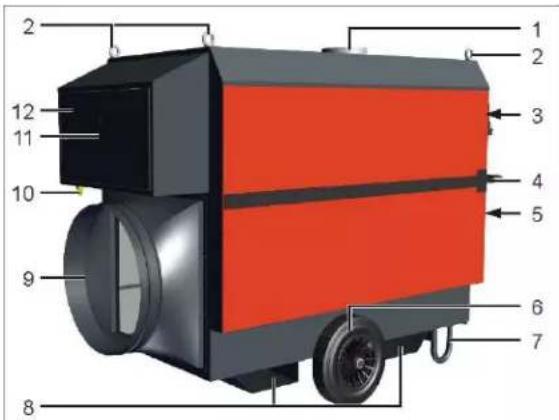
Fig. 17: K 120 Exterior view
| 1 | Exhaust pipe nozzle 2 | 2 | Transport eyebolts |
| 3 | Operating panel 4 | Handlebar | |
| 5 | Air inlet 6 | Wheel | |
| 7 | Stand or wheels (type R) | 8 | Transport straps for forklift trucks |
| 9 | Air outlet 10 | Oil pipe connection | |
| 11 | Inspection window 12 | Burner box |
The scope of supply includes:
- Air heater
- one strand oil pipe including foot valve and quick coupling connection
- Handlebar
- Operating manual burner
- Operating manual
The following are available as accessories:
- A console with which several devices can be stacked on top of each other. Further accessories, see Accessories [▶ 83].
How it functions
During operation, the heating oil is sucked in by the burner pump via the suction line from the tank
provided or from a permanently installed oil supply. The oil quantity required for the heat output is fed to the burner nozzle via the pressure line, sprayed into the combustion chamber and ignited there. The result is a flame which, together with its combustion gases, heats the combustion chamber and the heat exchanger. Excess heating oil pumped by the burner pump is returned to the burner pump.
The single-stage integrated system component burner (ISK burner) starts automatically as soon as a heat demand is present.
After a short preheating period, the temperature control switches on the warm air fan. The fan blows the cold air sucked in through the combustion chamber and the heat exchanger. This warms the air. The heated air exits on the opposite side through the blow-out nozzle.
The combustion exhaust gases are discharged via the exhaust gas duct. After switching off, the fan continues to run until the heat exchanger has cooled down.
NOTICE
Exhaust gas routing
The exhaust gas can be routed by the operator. The exhaust pipe used must be at least one metre long and protected with a rain hood. We recommend the use of HEYLO original accessories and spare parts (see Supplementary documents [▶ 79]).
Operation with room thermostats
When a room thermostat is connected, it indirectly controls the burner and ensures constant temperatures in the room to be heated. If the device is operated unobserved in closed rooms, a room thermostat must be used.
See also
Intended use [▶ 55]
15.2.1 Intended use
The device is used for heating halls, rooms and tents, as well as for point heating at repair points outdoors and in closed rooms, for thawing and heating machines, devices and pipelines, for drying rooms, hay and grain and as auxiliary heating in emergencies.
The devices can also be used as stationary solutions for halls and workshops.
The device may only be used for its intended purpose.
Intended use also includes observance of the operating conditions (see Operating conditions [▶ 51]).
Any other use or any application transcending the specified use is considered improper use. Improper use will result in all warranty claims becoming void.
See also
Technical details [▶ 78]
15.2.2 Improper use
Applications other than the intended use are prohibited. Improper use may lead to danger.
- Improper use is, for example, when unauthorised intervention is made in safety-relevant components or the specified operating conditions (e.g. fresh air limit values) are not complied with or the device is insufficiently maintained.
15.2.3 Foreseeable misuses
The following types of misuse can be envisaged:
- Operation while ignoring prescribed safety clearances
- Outdoor operation without frost and rain protection of the exhaust gas duct
-
Operation in living quarters and recreation rooms
-
Unattended operation without room thermostats installed
- Operation while ignoring applicable operating conditions
15.3 Device components
15.3.1 Burners
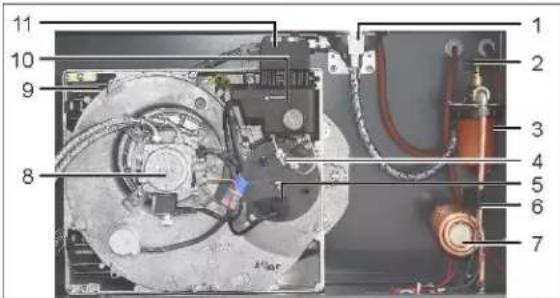
Fig. 18: Burner component
| 1 | Heating oil deaerator | 2 | Oil shut-off valve |
| 3 | Oil filter 4 | Nozzle holder with ignition electrode and nozzle | |
| 5 | Photocell (flame monitoring) | 6 | Thermostat for FPS |
| 7 | Heating oil preheating FPS | 8 | Oil pump |
| 9 | Burners 10 | Control device | |
| 11 | Burner plug |
The ISK series burner is located on the exhaust side of the combustion chamber.
A HEYLO FPS (FlowSecure Preheating-System) heating oil preheater is installed in the burner box. The oil filter and the heating oil deaerator for the single line system are also located here.
For maintenance purposes, the burner can be disconnected from the combustion chamber via the burner plug.
15.3.2 Fan
Depending on the type of unit, the fan is either radial or axial. The fan sucks in the ambient air. This flows past the heat exchanger element and is delivered to the blow-out nozzle.
Devices with radial fans achieve a higher discharge pressure. Long and branched hot air hoses can therefore be connected to these devices.
For 400 V units, the correct direction of rotation of the fan must be observed when connecting the device. The device must therefore be tested by switching it on briefly.
NOTICE! If the direction of rotation is incorrect, the fault signal lamp of the fan lights up.
See also
Assembly and connection [▶ 60]
15.3.3 Controls
The HEYtronic controller regulates the temperatures in the device.
After plugging in the mains plug, the controller displays the current blow-out temperature. In addition, the AL display flashes until the temperature at the outlet side has reached over 40^ C. If the temperature now falls below 30^ C after the fan has started, this process is repeated. At 40^ C and above, only the blow-out temperature is displayed.
The controller switches off the burner as soon as the temperature at the outlet side exceeds 85^ C. This may be the case if the connected warm air hoses are badly laid and represent a too high air resistance.
As soon as the blow-out temperature has cooled below 85 °C again, the burner starts automatically.
The status lights indicate the control of the burner and fan.
The control elements of the HEYtronic control are without function and only for setting the switching
values.
Programming may only be changed by service technicians. If you need further information, please contact the HEYLO Service department.
15.3.4 Safety devices
Persons can be seriously injured on the device if the safety devices are not properly installed and set. Do not modify, dismantle or take any of the safety devices out of operation. All the safety devices must be freely accessible at all times.
Familiarize yourself with all the safety devices; this way personal injury and/or damage to property can be prevented or minimized.
The following illustration shows the safety devices on the device.

Fig. 19: Safety devices
| 1 | Terminal box for burner | 2 | Oil shut-off valve |
| 3 | Burner interference suppression button | 4 | Photocell for flame monitoring |
| 5 | Intervention protection | 6 | Heat-insulated housing |
| 7 | Safety temperature |
limiter (STL)
The device has the following safety devices:
– Photocell for flame monitoring
- Shut-off valve
- Safety temperature limiter in the operating panel, for safety shut-down of the device in case of overheating
Signalling devices
Indicator lights are attached to the control panel to display the operating condition of the device:
- Green indicator lamp: Voltage is on, the device is switched on and working in heating operating mode.
- Red indicator light over temperature: Malfunction. The safety temperature limiter has tripped, the device is overheated.
- Red indicator light burner: There is a malfunction of the burner. After the malfunction has been rectified, the burner alarm is reset at the burner reset switch.
- Red indicator light fan (only for device with radial fan): There is a malfunction in the fan (wrong direction of rotation or mains connection). Switch the device off and then back on again. If the malfunction persists, shut down the device and contact the manufacturer.
- Fault signal lamp on the automatic oil combustion machine: If the fault signal lamp lights up, the burner must be suppressed. Press and hold the burner interference suppression button for 2 seconds. If the "burner" fault signal lamp on the control panel and the fault signal lamp on the oil combustion machine are extinguished, the burner will attempt to start.
WARNING! The burner must not be suppressed more than 3 times in succession. After that there is a danger of deflagration! Call a service technician.
Protective devices
Protective devices safeguard hazardous areas on the device. They have no influence on the machine's movements.
Separating protective equipment prevent or hinder direct access to the rotating or moving parts of the device. They may only be removed for set-up, maintenance or repair work and must be mounted again before restarting.
The device has the following protective equipment:
- Anti-tamper protection in front of the air openings
- Heat-insulated housing
- Protective cover on the electrical components
15.3.4.1 Emergency shut-down
In the event of a malfunction with the burner or an over temperature, the device switches off and the appropriate fault signal lamp light is lit up.
The device is not cooled with a power failure. This may cause the safety temperature limiter to trip.
Do not operate the device again until all the malfunctions and defects have been rectified.
15.4 Operating and display elements
The device is operated solely with the aid of the device switch on the control panel and with the room thermostat (optional).
NOTICE
Control panel R 120
The control panel of the R 120 device shown below can also be used as an example for devices with axial fans. The devices with axial fan do not have the fault signal lamp for a malfunction on the fan.

Fig. 20: Control elements
| 1 | Heating mode operating light | 2 | Temperature fault signal lamp |
| 3 | Burner fault signal lamp | 4 | Device switch |
| 5 | Burner operating hours counter | 6 | Fine fuse 6.3 A |
| 7 | Room thermostat connections | 8 | Power cable |
| 9 | Fan position fault signal lamp (with radial fans) | 10 | Safety temperature limiter (STL) |
| 11 | Temperature indicator |
The device switch turns the device on and off. If the device switch is switched to position [I], the device operates in heating mode. If the device switch is set to position [II], the fan is switched on and the device operates in ventilation mode.
Fault signal lamps are fitted on the control panel and on the automatic oil combustion machine. The indicator lights indicate the device's operating status (see section Safety devices [▶ 56]).
The temperature indicator shows the current temperature of the air at the blow-out nozzle.
The display of the digital temperature indicator shows the status lights of the burner and fan components. The status lights illuminate as soon as the device component has been switched on.
The reset button on the safety temperature limiter (STL) resets the STB after a malfunction that has caused the device to overheat has been rectified.
The operating hours counter displays the burner's operating hours.
A malfunction in the burner is reset via the reset button on the burner (rear of the device).
Room thermostat
With the optional room temperature controller, the device can be operated unattended. The device then runs in continuous operation until the set room temperature is reached in heating mode.
16 Transport and installation
The device has been assembled, set up and tested at the factory. Therefore there may still be oil residues in the pipes. In random samples, longer test runs are also carried out, which you can read off from the operating hours counter. In order to rule out any life-threatening injuries and damage to materials during transport and installation, please observe the following:
- Transport and installation work may only be carried out by qualified and authorised persons.
- Lifting tackle and slings must comply with the provisions of the accident prevention regulations.
- When selecting the lifting tackle and slings, consider the weight of the components and the centre-of-gravity (seeTechnical details [78]).
- Transport routes must be large enough. Doorways or gates must be at least 5 cm wider and higher than the transport unit, including the means of transport itself.
- Arrange for a third person to secure the transport route.
- All work on the electrical equipment must only be performed by qualified electricians.
The best and fastest installation is guaranteed if the described installation instructions is followed.
The following chapters provide an overview of the steps required to transport and install the machine.
- These installation instructions are no substitute for the necessary training of specialist personnel.

DANGER
Danger to life due to electric shock
Touching electrically live parts can be fatal.
a) Always turn the device off at the device switch before any change of location and pull out the mains plug.
b) Never pull the device by the mains plug and always move it using the handlebar provided.

CAUTION
Beware of obstacles on the ground
Inattention may lead to a risk of injury from tripping up.
a) Pay special attention to any obstacles on the ground.
b) Avoid points where you could stumble when laying cables, hoses and piping.
c) Use suitable cable ducts, bridges, etc.
a) Check the scope of delivery for completeness. Report transport damage or the incompleteness of the delivery to your specialist dealer immediately.
b) Dispose of the packaging in accordance with the valid local regulations.
c) If necessary, lift the device using either the lugs for the forklift truck or on the eyelets for the crane and place the device on the ground.
d) Pay attention to observing the Operating conditions [▶ 51].
16.1 Transport by forklift truck

WARNING
Danger of raised loads falling down
The sudden lowering or falling of loads that have been lifted is life-threatening.
a) Do not remain under raised loads!
b) Make sure that the machine is fully supported on the forks of the forklift truck during.
c) Observe the details of the centre of gravity on the transport packaging.
Follow these instructions in order to transport the machine safely with the forklift truck.
a) Only use forks of a suitable length.
b) Lift the machine at the designated side.
c) If necessary, place wooden beams under the machine for transport.
d) Transport the machine only on horizontally aligned forks of the forklift truck.

natural_image
Diagram of a forklift transporting a shipping container, with an inset showing a side view of a container being lifted (no text or symbols present)Fig. 21: Transport by forklift truck (diagram)
| A | Spacing between the forks | B | Forks longer than the material being moved |
| C | Place wooden beams underneath |
16.2 Transport by crane

WARNING
Danger of raised loads falling down
The sudden lowering or falling of loads that have been lifted is life-threatening.
a) Do not remain under raised loads!
b) Pay attention to the information on the transport packaging, where the means of transport are described!
Follow these instructionsto safely transport the machine/machine component with the crane.
a) Use trusses to transport the machine without the danger of any possible warping.
b) Only use the fixing eyelets to keep the machine/machine components in a vertical position when it is being transported by crane.
c) Always use all transport eye bolts. Always distribute the load over all the transport eye bolts provided, never lift the device using only one transport eye bolt.
d) Only lift the machine vertically.
16.3 Assembly and connection

WARNING
Risk of injury due to improper connection
The operation of mobile oil-heated hot air heaters can result in hazards due to oil leakage or faulty exhaust gas routing.
a) Only qualified and trained personnel may connect the device, install the exhaust gas duct and establish the oil supply.

CAUTION
Risk of injury due to the device tipping over or rolling away.
If the device is not erected stably, it may roll or tip over.
a) Prevent the device from rolling away or tipping over by placing it on a flat surface.
b) Place the device on its skids or brake the lockable wheels.

CAUTION
Risk of being crushed during installation of hoses and chimney
You may injure your hands when installing the oil supply and exhaust gas duct.
a) Wear protective gloves.

Attention
Destruction and sooting of the heat exchanger
Incorrect installation of the exhaust gas duct can lead to destruction of the heat exchanger.
a) Install an additional condensate trap for an extended exhaust gas duct.
b) Install the exhaust gas duct in such a way that no back pressure can occur in the exhaust gas duct at any time.

NOTICE
Use suitable extension cables
Consider the voltage drop when using extension cables. This should never exceed 3%.

NOTICE
Fireplace testing during operation in Germany
Fireplaces that are operated for longer than 3 months after commissioning must be inspected by the chimney sweep in accordance with the BlmSchV.
a) Mount the handlebar to the device using a Phillips screwdriver and the enclosed screws.
b) Position the device at the place of installation with the help of the handlebar.
c) Insert the mains plug into a suitable electrical outlet equipped with an RC circuit-breaker. For 400 V devices, pay attention to the indicated direction of rotation of the fan.
Installing the exhaust gas duct
a) For outdoor installation, place an original HEYLO exhaust pipe (see Accessories [▶ 83]) on the intended nozzle on the roof of the device.
b) To protect against rain or snow, install a rain hood. Make sure that this does not reduce the diameter of the exhaust pipe nozzle and the exhaust pipe.
c) When connecting to a permanently installed chimney, consult a chimney sweep. The minimum draft must be 0 PA.
d) If you extend the exhaust gas duct, install an additional condensate trap in which the condensate produced is collected. The resulting condensate can otherwise destroy the heat exchanger.
Installing the fuel tank

NOTICE
The heating oil supply is the responsibility of the operating company
The supply of the device with heating oil is not part of the delivery of the appliance and is the responsibility of the operating company.
The connection between heater and tank may only be established with original HEYLO components or in accordance with the regulations of technical regulation TRGS 509.
The tank must be protected against moisture penetration. In outdoor installations, the tank must be approved for this purpose.
HEYLO recommends winter heating oil or heating oil with flow improvers.
a) Make sure that the oil tank has a safety distance of at least 60 cm from the heater.
b) Plug the quick coupling connection of the supplied oil supply line onto the hydraulic connection on the device. Make sure that the connection coupling is seated correctly!
c) If the device is positioned lower than the tank, an anti-snub valve must be installed in the oil pipe.
d) Check the cleanliness of the tank and ensure regular cleaning to avoid malfunctions during operation.
Installing the hot air duct

NOTICE
Reduced heat output
The hot air duct must be laid out correctly. Poor hose routing can result in a reduced heat output or in the triggering of the safety temperature limiter.
a) Make sure that the maximum length of the hot air hoses is not exceeded (see Technical details [▶ 78]).
b) Avoid sharp bends and unnecessary lengths of hose.

NOTICE
Factory calculation of the hot air hose design
A 90 air outlet hood is included in the factory calculation.
a) Connect the hot air hoses as required. Devices with a radial fan discharge the heated air at a higher pressure than devices with an axial fan. Therefore, longer or branching hot air hoses can be connected to the devices with radial fans.
→ You have installed and connected the device.
The following illustration shows an example of a device installed outdoors.
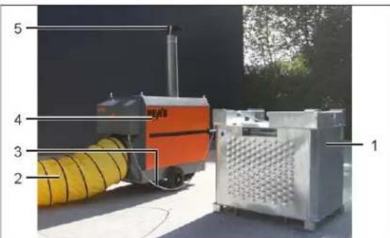
Fig. 22: Outdoor mounted device
| 1 | Oil tank 2 | Hot air hose | |
| 3 | Oil pipe 4 | Oil-fired hot air heater | |
| 5 | Chimney with weather protection |
17 Commissioning

NOTICE
Information
The factory setting of the burner is temperature-dependent. If the ambient conditions (temperature/air pressure) deviate considerably, the burner must be readjusted after commissioning.

NOTICE
Information
The values of the exhaust gas analysis for heating oil EL should be -12.5 % CO ^2 and -4 % residual oxygen.
√ The device is installed and connected, the exhaust gas duct is installed and the oil supply ensured.
√ The Operating conditions [▶ 51] for the place of installation have been met.
a) Make sure that the device is not standing on a wet base and ensure that it stands upright and safe.
b) Make sure that the power cable is undamaged.
For 400 V devices with CEE plug (three-phase current), the direction of rotation must be checked before commissioning:
a) Insert the power plug into the socket. Observe the running direction of the fan.
b) Start the device briefly at the device switch in ventilation operation mode. Check the direction of rotation of the fan. If the direction of rotation is incorrect, the red fault signal lamp of the fan lights up.
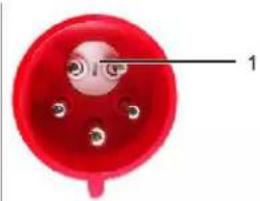
natural_image
Red electrical socket with three pins and a labeled section (no text or symbols beyond label)Fig. 23: Phase shifter
| 1 | Phase shifter |
c) If the running direction is incorrect, please turn the phase inverter in the plug.
d) Open the burner box.
e) Make sure that the shut-off valve for the heating oil supply is open.
f) Perform a functional test after connecting the power supply:
Set the device to heating mode on the operating panel.
All oil-carrying pipes and connectors must be checked for leaks (also in the combustion chamber).
Make sure that the heating oil is preheated or contains additives (flow improvers) that prevent paraffining at low temperatures.
g) Close the burner box.
h) Document the commissioning.
→ You have now commissioned the device.
See also
Safety [▶ 48]
18 Operation
18.1 The sequences for switching on and off
The device is operated solely with the aid of the device switch on the control panel and with the room thermostat (optional).
Switch on the device.
√ Commissioning is now completed.
NOTICE
Process flow
After switching on to the device switch, the device independently regulates the running times of the device components (fan, burner). For information, see the Operating modes [▶ 64] section.
a) Use the device switch to switch the device to the desired operating mode.
→ You have now switched on the device.
NOTICE
Switching on for the first time
When the burner is switched on for the first time, it may happen that the burner immediately goes into "malfunction", as the pipe system is not yet free of air. Ensure a bubble-free oil supply system. Further information can be found in the "Malfunctions during operation [▶ 66]" section and in the applicable operating manual of the burner manufacturer.
Switching the device off.

Attention
Damage to the heat exchanger by pulling out the mains plug
If the device is switched off by pulling the plug, the device cannot cool down and this can lead to damage to the combustion chamber, the flame monitor and the fan. The safety temperature limiter may switch off and lock under certain circumstances. The device will only restart after the safety temperature limiter has been unlocked.
a) Always switch off the device with the device switch and wait for the cooling phase (temperature indicator shows ≤ 30^ C) before disconnecting the device from the mains.
a) Turn the device switch to the position [0].
CAUTION! Do not pull the mains plug as long as the temperature indicator shows more than 30 °C and the fan is still running!
⇒ The temperature control switches the fan off with a time delay.
If the device has been operated in ventilation mode before being switched off, the fan switches off immediately and the device can be disconnected from the mains if necessary.
→ You have now switched off the device.
18.2 Operating modes
The device can release the sucked-in air into the room without heating (ventilation), or release heated air while the burner is running (heating).
Heating: The operating mode is activated by switching the device switch to position [1]. After switching on:
- The operating light is green
- The status light "Burner" on the HEYtronic display lights up
- The status light "Fan" on the HEYtronic display lights up at a temperature of 40 °C or higher.
- Starting the oil preheating
- After the preheating time (approx. 45 seconds) has elapsed, the burner starts
- As soon as the temperature sensor on the blow-out nozzle measures >40^ , the fan starts
CAUTION! Never disconnect the device from the mains before it has cooled down sufficiently!
After switching off, the fan continues to run until the temperature indicator shows ≤ 30^ C.
Ventilate: The operating mode is activated by switching the device switch to position [II]. After switching on:
- The fan switches on and conveys the sucked-in ambient air
18.3 Operating the external ambient temperature regulator
√ A room thermostat is installed at the room thermostat socket provided for this purpose on the front of the device.
√ The device is now ready for operation.
a) Set the room thermostat to the desired target temperature.
b) Turn the device switch to position [I].
⇒ The device starts the heating mode when the room temperature is lower than the set temperature.
The device will switch itself off as soon as the set temperature is reached. The fan continues to run until the temperature at the blow-out nozzle is ≤ 30^ C. If the temperature falls below the target temperature again, the device restarts the heating operation.
19 Malfunctions
Observe the following principles if you want to determine the cause of a malfunction search and malfunctions and eliminate it:
These tasks may only be carried out by trained and authorized specialists.
Interventions may only be carried out by the manufacturer or by persons authorized by the manufacturer during the statutory warranty period.
a) Let the device cool down.
b) Wear suitable protective clothing.
c) Disconnect the burner plug.
d) Close the oil shut-off valve.
e) Check all oil pipes and oil-carrying components for leakage.
f) Before recommissioning, install all the safety devices as attached at the factory.
g) Once the work has been completed, re-establish the connection between the burner and the combustion chamber and open the oil shut-off valve.
h) Check that the safety devices function properly.
i) After completing the task, remove all the tools and objects from the working area around the device.
Safety instructions regarding malfunctions

DANGER
Danger to life due to electric shock
Touching electrically live parts can be fatal.
a) Switch off the device, wait for the cooling down phase if necessary and unplug the mains plug.

WARNING
Danger of deflagration
If the burner is suppressed again and again without having started properly, there is a danger of deflagration!
a) Never suppress the burner more than 3 times in a row.
b) Call a service technician.

CAUTION
Danger due to missing safety covers
Missing safety covers can lead to injuries.
a) Before switching on the device, install all the safety covers that may have been removed for troubleshooting purposes.
b) Check all the safety devices before switching on the device.

NOTICE
Clean combustion chamber and check ex- haust gas values
After a malfunction with a sooty burner, the combustion chamber must always be cleaned and an exhaust gas analysis carried out. This work may only be carried out by a trained specialist.
19.1 Restarting after an unscheduled downtime
Power failure
After a power failure, the safety temperature limiter may have tripped and/or the burner may have gone to "malfunction".
a) Reset the STL (reset button on the control panel) and the burner (reset button on the burner box).
b) Starting the device.
If the device goes into malfunction again, it may have been damaged by overheating due to the power failure. In this case, shut down the device and arrange for the repair to be carried out.
⇒ You have now put the device into operation once again.
19.2 Malfunctions during operation

NOTICE
If the device is supplied with power by the mains cable, work on the electrical system may only be carried out by qualified electricians or an electrically instructed person in accordance with DGUV regulation 3 or DIN VDE 0105-100 or DIN VDE 0701-702.
Have repair work on the electrical, gas and oil connections for WLE carried out only by HEYLO Service or by HEYLO service partners.

NOTICE
It is vital to observe the relevant operating manual of the burner manufacturer. Operational disruptions may only be determined and eliminated by specialists.
Suppressor devices
Malfunctions can be reset with the aid of the suppressor devices.
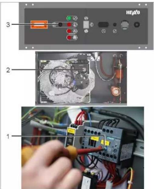
Fig. 24: Interference suppression
| 1 | Motor-protective circuit-breaker | 2 | Burner interference suppression button |
| 3 | Safety temperature limiter (STL) |
| Malfunction | Possible cause Remedy | |
| Safety temperature limiter (STL) fault signal lamp | STL has triggered due to over temperature | Eliminate cause of over temperature |
| Hose routing not in order | Check hose routing | |
| Airways constricted | Clean the airways | |
| Temperature of intake air too high | Reduce the temperature of the intake air | |
| Burner fault signal lamp | Fuel oil tank empty | Check heating oil supply |
| Oil supply interrupted | Check heating oil supply | |
| Burner malfunction | Press the interference suppression button on the burner (max. 3 times) | |
| Have the trouble-shooting carried out by a service technician | ||
| Fan fault signal lamp | The fan motor protection has tripped | Check mains supply cable. Measure the voltage at the device during operation. Provide if extensions are to be made in the supply line with a higher cross section |
| Power supply | breaks down | |
| Direction of fan rotation not correct | Check the direction of rotation of the fan again and possibly change the phase position (see Commissioning [62]) | |
| Fan motor blocked | Ensure free movement of the fan impeller | |
Tab. 15: End user malfunction table
| Malfunction | Possible cause Remedy |
| Burner does not work | No power Check the power cable and the mains connection. |
| Check supply with voltage tester, replace fuse if necessary | |
| No cap (cap contains current bridge) on connection for room thermostat | For operation without room thermostat: check whether the cap is on the room thermostat connection, since the device does not start without the cap, if necessary put on the cap |
| Room thermostat (if fitted) set too low | Set the room thermostat above the current room temperature |
| Room thermostat defective | Check room thermostat (by specialist only). If necessary, replace or bridge at the terminal on the device and switch by hand. |
| Oil combustion machine indicates malfunction (fault | Open the burner box. After a waiting period of ap-lamp lights up) prox. 1 minute, press the illuminated interference suppression button on the control device of the burner. The fault message on the control unit and the signal display must be extinguished. The burner then performs a new start attempt.NOTICE! During the first start-up it may be necessary to repeatedly press the burner interference suppression button until the burner has sucked-in air-free oil.WARNING! The burner may be suppressed / reset a maximum of 3 times, then call a service technician. |
| Safety temperature limiter triggered: Blow-out temperature too high, air cannot circulate freely, device could not cool down after switch-off | |
| Burner No oil Open oil shut-off | |
| Malfunction | Possible cause Remedy | |
| starts, but then goes to malfunction | valve | |
| Check the oil level in the tank, top up if necessary | ||
| Connect the oil pipe | ||
| Oil filter dirty | Clean nozzle filter, pump filter, prefilter, replace nozzle if necessary. | |
| Oil suction line leaking, pump sucks in air | Check and seal oil suction pipe | |
| Oil pump does not generate oil pressure | Have the oil pump adjusted or repaired by a specialist | |
| Suppress burner | ||
| Burner starts, but does not ignite and goes into malfunction | No ignition spark, ignition electrodes coked or out of adjustment | Pull out mains plug or switch off power and check nozzle holder. |
| Burner nozzle blocked | Pull out mains plug or switch off power: Unscrew the burner nozzle. Replace the nozzle with a new one. Always replace the nozzle, never clean it | |
| Flame goes out after burn-er ignition | Photocell dirty Pull | out the photo resistor and wipe with a clean cloth. In very dusty envi- |
| Malfunction | Possible cause Remedy |
| or burns unevenly | |
| Oil filter dirty Check and clean all oil filters: Pre-filters, pump filters, nozzle filters. | |
| Oil suction line leaking, pump sucks in air: Air bubbles in the oil of the return line | |
| Burner nozzle blocked | |
| Combustion air not correctly adjusted |
| Malfunction | Possible cause Remedy | |
| er. | ||
| Burner does not switch off | Room thermostat mounted in an unfavourable position. | Install the room thermostat in a different place. For correct control, it is important to install the room thermostat in the room to be heated in such a way that no cold air flow from windows, doors, etc. hits it. If applicable, relocate the room thermostat |
| Room thermostat defective | Have the room thermostat checked by a specialist, replace if necessary. | |
| Room thermostat switches burner off before desired room temperature is reached | Room thermostat mounted in an unfavourable position. | Install the room thermostat in a different place. For correct control, it is important to install the room thermostat in the room to be heated in such a way that no hot air flow or heat radiation, e.g. from the sun, neighbouring machines, hot water or steam pipes, hits it. If applicable, relocate the room thermostat |
| Fan does not start | Temperature controller does not work | Check whether the temperature controller is working, replace it if necessary. |
| No power supply | Measure the voltage at the fan with a two-pole voltage tester. | |
Tab. 16: Table of malfunctions
See also
Burner maintenance [▶ 72]
20 Cleaning and maintenance
The following principles apply when cleaning and maintaining the device:
These tasks may only be carried out by trained and authorized specialists.
a) Switch off the device before starting work, wait until the cooling phase has elapsed and then disconnect the mains plug.
b) Wear suitable personal protective equipment.
c) Disconnect the burner plug.
d) Close the oil shut-off valve.
e) Before recommissioning, install all the safety devices as attached at the factory.
f) Once the work has been completed, re-establish the connection between the burner and the combustion chamber and open the oil shut-off valve.
g) Check that the safety devices function properly.
h) After completing the task, remove all the tools and objects from the working area around the device.
i) Use only original spare parts and accessories.
Maintenance work must be documented.
The replacement of electrical components must be carried out by a qualified electrician.
DANGER
Danger to life due to electric shock
Touching electrically live parts can be fatal.
a) Switch off the device and pull out the mains plug.
CAUTION
Danger from the device being unintentionally started up
Uncontrolled starting of the burner or the fan can lead to injuries.
a) Switch off the device at the device switch and pull out the mains plug.

CAUTION
Danger due to missing safety covers
Missing safety covers can lead to injuries.
a) Before switching on the device, install all the safety covers that may have been removed for troubleshooting purposes.
b) Check all the safety devices before switching on the device.

CAUTION
Risk of injury from not wearing personal protective equipment
When cleaning and maintaining the device, you may injure yourself on sharp edges, or through inhaling or coming into contact with environmental toxins.
a) Wear protective gloves.

Attention
Damage to property through insufficient maintenance
Insufficient maintenance leads to higher wear and expensive repairs.
a) Carry out the necessary maintenance work in accordance with the manufacturer's instructions.
b) Observe the manufacturer's instructions on looking after the mechanical components.
c) In the event of damage to the mechanical equipment, take the device out of operation immediately and arrange for professional repair using original spare parts.

NOTICE
Performing regular maintenance
Regular maintenance constitutes one element of the intended use of the device and it is an absolute prerequisite for safe and efficient operation.
20.1 Cleaning the device

NOTICE
Suitable cleaning agents
You can obtain suitable cleaning agents for cleaning your device from your dealer or directly from HEYLO.
The cleaning intervals for the device will depend on the conditions of use. Therefore check and clean the device regularly.
Cleaning can be performed with compressed air, a vacuum cleaner or by wiping with a damp cloth.
CAUTION! Never use a hose or high pressure cleaner.
The electrical system must be checked regularly for signs of damage.
In order to work correctly and reliably, the device's oil filter must be periodically checked and cleaned (see Replacing oil filter [73]).
Proceed as follows to clean and check the condition of the device:
a) Switch off the device at the device switch and wait until the temperature at the blow-out nozzle has dropped to ≤ 30^ C.
b) Pull out the mains plug.
Clean the housing
a) Open the safety cover.
b) Clean the safety cover and the housing with a damp lint-free cloth and a mild detergent. The original gloss can be restored with polish.
c) Close the safety cover as intended at the factory.
→ The housing is now cleaned.
Clean heat exchanger
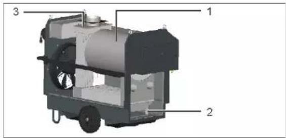
Fig. 25: Heat exchanger
| 1 | Heat exchanger 2 | Cleaning opening on discharge side | |
| 3 | Cleaning opening on the exhaust pipe nozzle |
Two openings are provided for cleaning the heat exchanger on the K 160 and K 120. One is located on the exhaust pipe nozzle.
a) Loosen the screw connection of the flange and remove the cover plate.
b) Open the first cleaning opening of the heat exchanger.
The second cleaning opening of the heat exchanger is located on the outlet side of the heat exchanger.
a) Remove the maintenance covers and open the second cleaning opening of the heat exchanger.
b) Clean the heat exchanger with a pipe brush and vacuum the dissolved soot with a suitable vacuum cleaner.
c) Mount the safety covers in the same way as they were installed at the factory.
→ You have now cleaned the heat exchanger.
Inspecting the electrical system
DANGER
Touching electrically live parts can be fatal.
Improper or inadequate inspection and maintenance can lead to device components becoming live during operation due to a defect.
a) Inspection of the electrical system should only be conducted by a qualified electrician.
b) After the work has been completed, install and test all the safety devices as intended.
a) Check all the device's electrical components visibly for signs of external damage, loose contacts and contamination. Remove the safety cover in order to inspect the internal wiring. Remove any external contamination with a lint-free cloth and replace any defective or damaged components.
b) If used commercially in Germany: Conduct an annual DGUVV3 examination in accordance with the Berufsgenossenschaft (trade association) requirements and keep a record of it.
⇒ The inspection of the device's electrical system is now complete.
20.2 Burner maintenance
NOTICE
In addition, observe all instructions regarding maintenance intervals and handling of the burner components in the applicable operating manual of the burner manufacturer.
The burner maintenance must be carried out regularly (observe the instructions in the maintenance table and in the operating manual of the burner manufacturer) and includes the following work:
- Replace oil filter
- Replace oil nozzle
- Adjust the burner head
- Adjust the combustion air
- Set pump pressure
- Carry out exhaust gas analysis
All burner maintenance work must be carried out before starting work:
a) Allow the device to cool sufficiently before starting work and then unplug the power cord.
b) Disconnect the burner from the combustion chamber.
20.2.1 Replacing oil filter
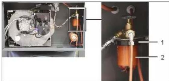
natural_image
Interior view of an electronic device with labeled components (no readable text or symbols)Fig. 26: Replacement oil filter
| 1 | Union nut 2 | Filter cup with filter insert |
The oil filter must be checked regularly and replaced if necessary. Proceed as follows:
√ Ensure there is an absorbent cloth for collecting the heating oil escaping from the filter is available next to the working area.
a) Loosen the union nut.
b) Hold the cloth under the filter device and pull the filter cup down.
Make sure that the escaping oil is collected.
c) Remove oil residue and dirt from the inside of the burner box.
d) Remove the old filter cartridge and insert a new one.
e) Fasten the filter cup and the union nut.
f) Dispose of the old filter insert and oil residues properly.
→ You have changed the oil filter.
20.2.2 Replacing oil nozzle

Fig. 27: Replacement oil nozzle
| 1 | Oil pipe 2 | Photocell | |
| 3 | Nozzle holder mounting screw | 4 | Nozzle holder |
| 5 | Nozzle holder (dismantled) | 6 | Oil nozzle |
If the oil nozzle is clogged or worn, it can be replaced as follows:
a) Disconnect the oil pipe and the ignition pipe.
b) Disassemble the nozzle holder.
c) Replace the oil nozzle.
d) Reassemble all previously disassembled or loosened components as provided in the factory.
e) Check that the oil pipes are tight.
→ You have now changed the oil nozzle.
20.2.3 Setting the burner

NOTICE
Observe the applicable operating manual of the burner manufacturer as well as all information on the burner from the tableMalfunctions during operation [▶ 66].

Fig. 28: Burner settings
| 1 | Burner head adjusting screw | 2 | Combustion air set screw |
| 3 | Connection for pressure gauge | 4 | Pump pressure adjusting screw |
Adjust the burner head
Check the burner head setting regularly. If necessary, the burner head can be readjusted using the adjusting screw.
Adjust the combustion air
a) Loosen the lock nut on the combustion air adjusting screw.
b) Adjust the combustion air at the adjusting screw from below using a screwdriver.
c) Perform a Exhaust gas analysis [▶ 74].
→ You have now adjusted the combustion air.
Set pump pressure
a) Screw the pressure gauge (article no. 4000005) to the connection.
b) Use a screwdriver to adjust the pressure on the pump pressure adjustment screw.
NOTICE! Turning to the right increases the pressure, turning to the left decreases the pressure.
c) Perform a Exhaust gas analysis [▶ 74].
⇒ You have set the pump pressure.
See also
Maintenance schedule [▶ 76]
20.2.4 Exhaust gas analysis
a) Drill a hole at a height of 400 mm with a diameter of 8 mm into the exhaust gas duct.

Fig. 29: Installed device for exhaust gas analysis
| 1 | Connection point in the exhaust gas duct | 2 | Measuring device for exhaust gas analysis |
b) Connect the exhaust gas analysis measuring device (part no. 4000040) to the device.
c) Select the program for the exhaust gas analysis on the device and switch on the measuring device.
d) Starting the device.
⇒ The burner starts.
e) Wait for the calibration phase of the burner (duration: 5 minutes).
f) Insert the measuring probe through the borehole in the exhaust pipe.
g) Start the measurement on the measuring device.
⇒ The values are output on the measuring device and can be read.
h) Use the table below to check whether the exhaust gas values are within the limits.
i) Adjust the burner if necessary.
j) Carry out a soot measurement using the soot pump (article no. 4000000).
→ You 'have completed the exhaust analysis.

NOTICE
The values of the exhaust gas analysis for heating oil EL should be -12.5 % CO ^2 and -4 % residual oxygen.

NOTICE
If the specified exhaust gas values are not achieved, the burner settings must be readjusted.
Exhaust gas limit values
For Germany: Regulated in BlmSchG, status 26/01/2010 § 1 and § 8.
| Nominal heating output in kW | Soot index Max. exhaust gas losses in % |
| >4 <25 1 11 | |
| >25 <50 1 10 | |
| >50 1 9 |
Tab. 17: Permissible exhaust gas limit values in Germany
Exception: The measurement must be carried out 3 months after the initial commissioning.
For Austria: Regulated in the regional provisions of the LHKG 2008.
| Nominal heating output in kW | Soot index Max. | exhaust gas losses in % |
| >4 1 22 | ||
| >4 <10 1 19 | ||
| >10 1 16 |
Tab. 18: Permissible exhaust gas limit values in Austria
| Nominal heating output in kW | Soot index | CO content | NO _x content |
| >350 1 max. 20 | mg/MJ | 70 mg/MJ (max. 252.80 mg/kWh) |
Tab. 19: Permissible exhaust gas limit values in Austria (Burgenland), by nominal heating output
Exceptions:
- The NO_x limit value applies only to wood combustion systems (35 mg/MJ).
- The NO_x limit value must not be exceeded by more than 100% for instantaneous water heaters, storage water heaters and individual furnaces.
20.3 Maintenance schedule
| Component | Action to be taken* | Description of the action | Performed by** |
| Entire machine | V Check | for signs of external damage and leakage | CO |
| * V = visual inspection, Ch = checking, R = replacement, C = cleaning | |||
| **CO = customer (operator), CS = customer (specialist), M = manufacturer | |||
Tab. 20: Daily maintenance schedule
| Component | Action to be taken* | Description of the action | Performed by** |
| Oil filter A | Replace | filter, see burner operating manual | CS |
| Oil nozzle | A Replace | nozzle, see operating manual for burner | CS |
| Burners C | Thoroughly clean internal parts, refer to burner operating manual | CS | |
| * V = visual inspection, Ch = checking, R = replacement, C = cleaning | |||
| **CO = customer (operator), CS = customer (specialist), M = manufacturer | |||
Tab. 21: Annual maintenance schedule
| Component | Action to be taken* | Description of the action | Performed by** |
| Combustion chamber | C Clean | combustion chamber and replace all seals, see burner | CS |
| Component | Action to be taken* | Description of the action | Performed by** |
| operating manual |
Tab. 22: Every 2 years
NOTICE
Check exhaust gas values
All maintenance work must be checked and completed by an exhaust gas analysis. This work may only be carried out by a trained specialist.
20.4 Wear and spare parts
Spare parts must meet the technical requirements specified by HEYLO. HEYLO original spare parts must meet stringent requirements.
EYLO assumes no warranty for any damage caused by the use of spare parts from other manufacturers.
Enquiries and orders In connection with wear and spare parts, please contact your dealer or HEYLO directly, providing the following information:
- Device type,
- Serial number,
- Year of construction,
- Designation of the component,
- Quantity,
- Form of shipping.
See also
Contacting DANTHERM GmbH [▶ 48]
20.5 Customer service by the manufacturer
HEYLO recommends signing a maintenance contract with the HEYLO Service Partner.
See also
Contacting DANTHERM GmbH [▶ 48]
21 Repairs
The following section describes who may repair the device and how it can be repaired.

NOTICE
Repairs may only be carried out by staff authorized by the manufacturer during the warranty period of the device.
Repairs performed by the company operating the device
After the statutory warranty has expired, repairs may be carried out by the company operating the device, provided appropriate expertise is shown. HEYLO will not assume any liability for these repairs.
Contact the HEYLO service department or your dealer if you have any questions about repairs.
See also
Contacting DANTHERM GmbH [▶ 48]
22 Decommissioning, storage and disposal
The following principles apply for the decommissioning, storage and disposal of the device:
These tasks may only be carried out by trained and authorized specialists.

DANGER
Danger to life due to electric shock
Touching electrically live parts can be fatal.
a) Switch off the device and pull out the mains plug.
22.1 Decommissioning
Temporary decommissioning
a) Switch off the device at the device switch and pull out the mains plug.
b) Clean the device (see Cleaning and maintenance [▶ 70]).
⇒ The device has now been temporarily decommissioned.
Final decommissioning
√ Carry out all the steps needed for temporary decommissioning.
a) Disconnect all incoming and outgoing lines (discharge and power supply lines).
⇒ You have finally taken the device finally been decommissioned
See also
Contacting DANTHERM GmbH [▶ 48]
22.2 Storing the device
Store the device dry.
Before storing the device, start the heating operation briefly with winter diesel to fill the pipes with frost-proof oil.
See also
Technical details [▶ 78]
Operating conditions [▶ 51]
22.3 Disposal
The device is largely made of recyclable materials. It does not represent any danger to the operator and the environment when handled properly. However, operation of the device may lead to the generation of waste and waste water containing harmful and/or environmentally hazardous substances (air filters and condensate). These materials must be disposed of properly, in accordance with the regulations.
The individual components of the device (e.g. pumps, metal components, etc.) must be taken to a qualified disposal and recycling company. Appoint a qualified, specialist company to dispose of and recycle the device.
See also
Contacting DANTHERM GmbH [▶ 48]
23 Technical details
| Type: K 120 K 120 R | K 160 | K 160 R | ||
| Article No. 110 | 163 | 110163 | 110163 | 110163 |
| 5 | 6 | 7 | 8 | |
| Nominal heat load [kW] | 120 120 156 161 | |||
| Nominal heating output [kW] | 110 110 146 151 | |||
| Hot air volume flow at Δp [m3/h] | 9420 10567 11156 12767 | |||
| Temperature increase Δt [K] | 42 47 40 45 | |||
| Max. available static pressure [Pa] | 300 550 290 680 | |||
| Available pressure at 50 % air output | 170 250 150 450 | |||
| Rec. hose lengths à 7.6 m | 3 5 3 9 | |||
| Sound level at a distance of 5 m [dB(A)] | 63 63 66 61 | |||
| Power 230/50 | 400/50 | 230/50 | 400/50 | |
| Type: K 120 K 120 R | K 160 K 160 R | |
| connection [V/Hz] | ||
| Current con-sumption [A] | 7.4 5.7 10.4 6.8 | |
| Power con-sumption [kw] | 1.65 3.08 2.25 | 4.8 |
| Protection class [IP] | 44 44 44 44 | |
| Fuel con-sumption [kg/h]Heating oil EL | 10.1 10.1 13.1 | 13.9 |
| Exhaust gas loss [%] | 9 9 9 9 | |
| required chimney drau-ght [Pa] | 0 0 0 0 | |
| Exhaust gas mass flow max. [kg/s] | 0.054 0.09 | 0.099 0,099 |
| Device dimensions: | ||
| Length [mm] | 1900 2101 | 2075 2326 |
| Width [mm] | 880 880 880 880 | |
| Height [mm] | 1400 1400 | 1400 1400 |
| Weight with burner (kg) | 290 320 330 350 | |
| ∅ exhaust pipe [mm] | 200 200 200 200 | |
| ∅ blow-out nozzle [mm] | 550 550 550 550 | |
| Fan thermo-stat TR [°C] (HEYtronic control) | 85 85 85 85 | |
| Temperature monitor TW [°C] (HEY-tronic control) | 40 40 40 40 | |
| Safety temperature limiter STL [°C] | 100° (fixed) 100° (fixed) | 100° (fixed) 100° (fixed) |

NOTICE
The technical details may be changed without prior notice during the course of development. Some of the values are approximate.
24 Supplementary documents
24.1 List of wear and spare parts Spare parts list for K 120 (R) and K 160 (R)

Fig. 30: Spare parts drawing K 120/K 160

Fig. 31: Spare parts drawing K 120R/K 160R
| No. | Item no. | 1* | 2* | 3* | 4* | Description |
| 1 | 1230180 | ● | ● | ● | Burner RG3 H | |
| 2 | 1400100 | ● | ● | ● | Blow-out nozzles | |
| 3 | 1400101 | ● | ● | Complete foot | ||
| 4 | 1261209 | ● | Wheel caster stif-fener | |||
| 5 | 1400103 | ● | ● | ● | Complete handle | |
| 6 | 1400140 | ● | ● | Complete heat exchanger (120KW) | ||
| 6 | 1400104 | ● | Complete heat exchanger (160KW) | |||
| 7 | 1400105 | ● | Fan F | N-056-4EL |
| No. | Item no. | 1* | 2* | 3* | 4* | Description |
| 7 | 1400106 | ● | Fan FN-063-4ED | |||
| 7 | 1400107 | ● | Radial fan GR050 | |||
| 7 | 1400108 | ● | Radial fan GR056N | |||
| 8 | 1400109 | ● | Plastic strip 1400 mm lg. | |||
| 8 | 1400110 | ● | ● | Plastic strip 1580 mm lg. | ||
| 8 | 1400111 | ● | Plastic strip 1830 mm lg. | |||
| 9 | 1261207 | ● | ● Swivel castor with stop | |||
| 10 | 1261208 | ● | ● Swivel castor without stop | |||
| 11 | 1400112 | ● | ● | ● | ● Wheel VPP 355/25G | |
| 12 | 1400113 | ● | ● | ● | ● Adjusting ring 25 mm | |
| 13 | 1400114 | ● | ● | ● | ● Toc-Uno-A heating oil deaerator | |
| 14 | 1400115 | ● | ● | ● | ● Heating oil filter single single-line 3/8" | |
| 15 | 1630644 | ● | ● | ● | ● Oil filter insert for single-line oil filter | |
| 16 | 1400116 | ● | ● | ● | ● Door lock | |
| 17 | 1400117 | ● | ● | ● | ● Crane eyes M12 | |
| 18 | 1630854 | ● | ● | ● | ● Oil connection nipple (device) | |
| 19 | 1630853 | ● | ● | ● | ● Oil connection coupling (drum fitting) | |
| 20 | 1400118 | ● | ● | ● | ● Temperature controller TK24NF | |
| 21 | 1400119 | ● | ● | ● | ● Spiral for oilpreheating | |
| 22 | 1400120 | ● | ● | ● | ● | Heating cartridge |
| 23 | 1262200 | ● | ● | ● | ● | Drum fitting 3 m. single strand |
| 24 | 1400141 | ● | ● | ● | ● | Foot valve for drum fitting |
| 25 | 1240103-1 | ● | ● | ● | ● | Digital thermostat Heytronic |
| 26 | 1240103-4 | ● | ● | ● | ● | Resistance sensor PT100 |
| 27 | 1400121 | ● | ● | ● | ● | Signal lamp green |
| 28 | 1400122 | ● | ● | ● | ● | Signal lamp red |
| 29 | 1400123 | ● | ● | ● | ● | Safety temperature limiter (STL) |
| 30 | 1660150 | ● | ● | ● | ● | Cap for STL |
| 31 | 1660980 | ● | ● | ● | ● | Rocker switch 1-0-2 |
| 32 | 1400124 | ● | ● | Relay | ||
| 33 | 1400125 | ● | ● | ● | ● | Fuse holder |
| 34 | 1400126 | ● | ● | ● | ● | Control fuse 6.3A slow blow |
| 35 | 1400127 | ● | ● | Connection board 3RU2916 | ||
| 36 | 1400128 | ● | Contactor 3RT2015-1AP01 | |||
| 36 | 1740138 | ● | Contactor 3RT2016-1AP01 | |||
| 37 | 1400129 | ● | ● | Over current relay 4.5/6.3A | ||
| 38 | 1400130 | ● | ● | Supply pipe 5x1,5x5000lg. | ||
| 38 | 1400131 | ● | ● | Supply pipe 3x1,5x5000lg. | ||
| No. | Item no. | 1* | 2* | 3* | 4* | Description |
| 39 | 1400132 | ● | ● | ● | Bulkhead mount-ing housing for RT | |
| 40 | 1400133 | ● | ● | ● | Female insert for RT | |
| 41 | 1400134 | ● | ● | ● | Cap for room thermostat (RT) | |
| 42 | 1400135 | ● | ● | ● | Burner flange seal | |
| 43 | 1400136 | ● | ● | ● | Cleaning cover seal (15 m roll) | |
| 44 | 1400137 | ● | ● | ● | Stacking tabs (light) | |
| 45 | 1440028 | ● | ● | ● | Operating hours counter | |
| 46 | 1400138 | ● | ● | ● | Axis | |
| 47 | 1400139 | ● | ● | ● | Door switch box |
*1: K 120; 2: K 120 R; 3: K 160; 4: K 160 R
Spare parts list oil burner RG3 H (for K 120 / K 160)
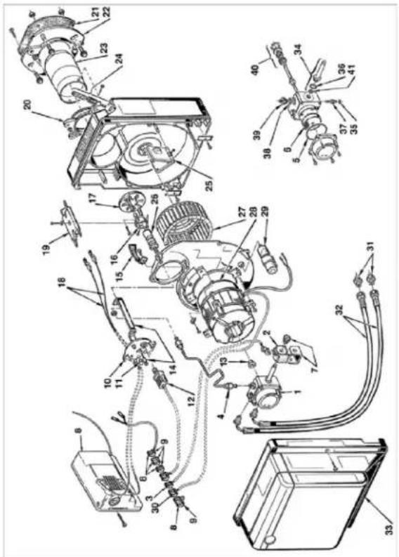
Fig. 32: Spare part drawing oil burner
| No. | HEYLOArt. No. | Description |
| 1 | 1630549 | R.B.L Pump |
| 2 | 1400612 | Solenoid valve coil |
| 3 | 1655523 | Solenoid valve connection cable |
| 4 | 1655043 | Pressure pipe |
| 5 | 1560212 | O-ring seal |
| 6 | 1630654 | Oil pump filter insert |
| 7 | 1400657 | Retaining bracket with screw |
| 8 | 1420016 | Control unit M0550 |
| 9 | 1655619 | Connection system |
| 10 | 1630431 | Nozzle holder flange |
| 11 | 1655003 | Sealing plugs |
| No. | HEYLO Art. No. | Description |
| 12 | 1420124 | Photo conductive cell |
| 13 | 1650517 | Pump coupling |
| 14 | 1630403 | Nozzle holder |
| 15 | 1655006 | Air baffle |
| 16 | 1630420 | Baffle plate holder |
| 17 | 1630422 | Baffle plate |
| 18 | 1630422 | Cable ignition electrodes |
| 19 | 1630340 | Electrode block |
| 20 | 1630428 | Burner flange |
| 21 | 1655009 | Boiler flange seal |
| 22 | 1655010 | Boiler flange |
| 23 | 1655008 | Flame tube |
| 24 | 1655519 | Air regulation |
| 25 | 1655518 | Air damper |
| 26 | 1630421 | Nozzle holder |
| 27 | 1651748 | Blower wheel |
| 28 | 1400202 | Motor |
| 29 | 1400325 | Capacitor 6.3 μF |
| 30 | 1655564 | Socket for motor |
| 31 | 1655019 | Connection nipple |
| 32 | 1630424 | Oil hose |
| 34 | 1655576 | Body solenoid valve |
| 35 | 1655020 | O-ring seal |
| 36 | 1655562 | O-ring seal |
| 37 | 1262353 | Pressure regulating screw |
| 38 | 1655560 | O-ring seal |
| 39 | 1655563 | Connecting flange seal |
| 40 | 1560213 | Drive shaft sealing insert |
| 41 | 1560214 | O-ring seal |
| 42 | 1630252 | Oil nozzle K120 + K120 R 2.5Gph60° B |
| 42 | 1630005 | Oil nozzle K160 + K160 R 3.25Gph60° B |
24.2 Accessories
| Item no. | Description |
| 1700502 | Exhaust pipe 1 m |
| 1700523 | Rain hood 200 mm |
| 1261200 | Circulating air connection K 120, K 120R, K 160R |
| 1261205 | Circulating air spigot K 160 |
| 1250071 | Hot air hose type A 550 mm |
| 1250084 | Hot air hose type B 550 mm |
| 1250052 | Hot air hose type C 550 mm (with transport bag) |
| 1200008 | Adapter from 1x550 to 3x305 |
| 1240100 | Wet room thermostat (analogue) with 10 m cable |
| 1240103 | Wet room thermostat (digital) (order cable 1900006!) |
| 1900006 | 10 m cable for wet room thermostat (digital) |
| 1261206 | Wheel set for K 120 and K 160 |
| 1261202 | Heavy container console |
| 1261203 | Stacking console for stacking devices in the warehouse |
| 1261204 | Console for mounting chimney and accessories on the device |
| Item no. | Description |
| 1200130 | Tank heater |
| 4000026 | Tool set for repairing K-devices |
| 4000040 | Exhaust gas analyser for burner maintenance |
NOTICE
Customer service
If you are unsure about which accessories are suitable for your device, contact your dealer or the Heylo customer service.
24.3 Declaration of conformity
- Managing Director-
EC Declaration of Conformity IIA In accordance with the EC Machinery Directive 2006/42/EC

For device series: Oilheaters
Type: K120, K160,
K120-R,K160-R
Dantherm GmbH, Oststrasse 148, 22844 Norderstedt, Germany, hereby declares that the design and construction of the equipment described in this document in the version provided by us comply with the health and safety requirements as defined in EC Directive 2006/42/EC.
Applicable EC Directives:
Machinery directive 2006/42/EC
EMC Directive 2014/30/EU
ERP Directive 2009/125/EC
RoHS 2011/65/EU
Changes to the machinery made without our consent will render this declaration void.
Standards applied:
DIN EN IEC 55014-1:2022-12
DIN EN IEC 55014-2:2022-10
Name and signature of the authorized representative of the technical documentation:
Norderstedt, Germany,
24.08.2023
Manfred Föhlisch
24.4 Circuit diagram
![Copyright from ISO 19033444 C:\Program Files\Temperature\Temperature\Temperature\Temperature\Temperature\Temperature\Temperature\Temperature\Temperature\Temperature\Temperature\Temperature\Temperature\Temperature\Temperature\Temperature\Temperature\Temperature\Temperature\Temperature\Temperature\Temperature\Temperature\Temperature\Temperature\Temperature\Temperature\Temperature\Temperature\Temperature\Temperature\Temperature\Temperature\Temperature\Temperature\Temperature\Temperature\Temperature\Temperature\Temperature\Temperature\Temperature\Temperature\Temperature\Temperature\Temperature\Temperature\Temperature\Temperature\Temperature\Thermal Desorption\Thermal Desorption\Thermal Desorption\Thermal Desorption\Thermal Desorption\Thermal Desorption\Thermal Desorption\Thermal Desorption\Thermal Desorption\Thermal Desorption\Thermal Desorption\Thermal Desorption\Thermal Desorption\Thermal Desorption\Thermal Desorption\Thermal Desorption\Thermal Desorption\Thermal Desorption\Thermal Desorption\Thermal Desorption\Thermal Desorrm\nThermal Desorption\nThermal Desorption\nThermal Desorption\nThermal Desorption\nThermal Desorption\nThermal Desorption\nThermal Desorption\nThermal Desorption\nThermal Desorption\nThermal Desorption\nThermal Desorption\nThermal Desorption\nThermal Desorption\nThermal Desorption\nThermal Desorption\nThermal Desorption\nThermal Desorption\nThermal Desorption\nThermal Desorption\nThermal Desorption\nThermal Desarson\nThermal Desarson\nThermal Desarson\nThermal Desarson\nThermal Desarson\nThermal Desarson\nThermal Desarson\nThermal Desarson\nThermal Desarson\nThermal Desarson\nThermal Desarson\nThermal Desarson\nThermal Desarson\nThermal Desarson\nThermal Desarson\nThermal Desarson\nThermal Desarson\nThermalDesarson\nThermalDesarson\nThermalDesarson\nThermalDesarson\nThermalDesarson\nThermalDesarson\nThermalDesarson\nThermalDesarson\nThermalDesarson\nThermalDesarson\nThermalDesarson\nThermalDesarson\nThermalDesarson\nThermalDesarson\nThermalDesarson\nThermalDesarson\nThermalDesarson\nTheoretical Temperature/°C\nTheoretical Temperature/°C\nTheoretical Temperature/°C\nTheoretical Temperature/°C\nTheoretical Temperature/°C\nTheoretical Temperature/°C\nTheoretical Temperature/°C\nTheoretical Temperature/°C\nTheoretical Temperature/°C\nTheoretical Temperature/°C\nTheoretical Temperature/°C\nTheoretical Temperature/°C\nTheoretical Temperature/°C\nTheoretical Temperature/°C\nTheoretical Temperature/°C\n[1] [2] [3] [4] [5] [6] [7] [8] [9] [10] [11] [12] [13] [14] [15] [16] [17] [18] [19] [20] [21] [22] [23] [24] [25] [26] [27] [28] [29] [30] [31] [32] [33] [34] [35] [36] [37] [38] [39] [40] [41] [42] [43] [44] [45] [46] [47] [48] [49] [50] [51] [52] [53] [54] [55] [56] [57] [58] [59] [60] [61] [62] [63] [64] [65] [66] [67] [68] [69] [70] [71] [72] [73] [74] [75] [76] [77] [78] [79] [80] [81] [82] [83] [84] [85] [86] [87] [88] [89] [90] [91] [92] [93] [94] [95] [96] [97] [98] [99] [100]](/content/2026/06/1358865/images/592739b0f595de8e80d0a339b949d36342961b1cab4a4936bad68567310ac62a.jpg)
SIE HABEN FRAGEN? WIR HELFEN IHNEN GERN! Do you have any questions? We are happy to help you!
HEYLO Kundendienst – Technischer Support und Service HEYLO Customer Service – Technical Support and Service
Tel. +49 (0) 42 02 - 97 55 15
For your construction site, production facility or event via the HEYLO rental network:
www.heylo-mietservice.de
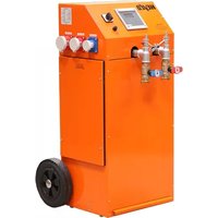
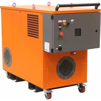


- Translation of the original instruction manual
- Dantherm GmbH
- Schutzvermerk
- Table of contents
- About this operating manual 46
- Safety 48
- Product description 53
- Transport and installation 58
- Commissioning 62
- Operation 63
- Malfunctions 65
- Cleaning and maintenance 70
- Repairs 77
- Decommissioning, storage and disposal --- 77
- Technical details 78
- Supplementary documents 79
- About this operating manual
- NOTICE
- Sample illustrations
- The purpose of this manual.
- Keep the manual safe and at hand at all times
- Symbols and definitions used
- Instructions
- DANGER
- Warning indicating an immediate danger for people
- WARNING
- Warning indicating a potential danger for people.
- CAUTION
- Attention
- Warning of possible damage to property.
- Example
- Electric shock due to high voltage (type and source of danger)
- Information
- Mandatory symbols
- Symbol Meaning
- Tab. 12: Mandatory symbols
- Markings in the text
- Action instructions
- Warranty
- Contacting Dantherm GmbH
- Safety
- Avoiding hazardous situations
- Information on transport and installation
- Notes on operation
- Maintenance and troubleshooting instructions
- Information on electrical equipment
- Notes on fire protection
- Requirements for heating oil supply
- Reliable, above-ground oil pipes and tank installations
- Requirements for oil pipes
- Notes on environmental protection
- Operating conditions
- Installation rooms
- For installation of the device in closed, well-ventilated rooms without installed chimney connection:
- Outdoor installation of the device
- Safety clearances
- Personal protective equipment
- Residual hazards
- Product description
- Identification of the machine
- Rating plates of the device types
- General description
- Exhaust gas routing
- Operation with room thermostats
- See also
- Intended use
- Improper use
- Foreseeable misuses
- Device components
- Burners
- Fan
- NOTICE! If the direction of rotation is incorrect, the fault signal lamp of the fan lights up.
- Controls
- Safety devices
- limiter (STL)
- Signalling devices
- Protective devices
- Emergency shut-down
- Operating and display elements
- Control panel R 120
- Room thermostat
- Transport and installation
- Danger to life due to electric shock
- Beware of obstacles on the ground
- Transport by forklift truck
- Danger of raised loads falling down
- Transport by crane
- Assembly and connection
- Risk of injury due to improper connection
- Risk of injury due to the device tipping over or rolling away.
- Risk of being crushed during installation of hoses and chimney
- Destruction and sooting of the heat exchanger
- Use suitable extension cables
- Fireplace testing during operation in Germany
- Installing the exhaust gas duct
- The heating oil supply is the responsibility of the operating company
- Reduced heat output
- Factory calculation of the hot air hose design
- Commissioning
- Operation
- The sequences for switching on and off
- Process flow
- Switching on for the first time
- Damage to the heat exchanger by pulling out the mains plug
- Operating modes
- CAUTION! Never disconnect the device from the mains before it has cooled down sufficiently!
- Operating the external ambient temperature regulator
- Malfunctions
- Danger of deflagration
- Danger due to missing safety covers
- Clean combustion chamber and check ex- haust gas values
- Restarting after an unscheduled downtime
- Power failure
- Malfunctions during operation
- Suppressor devices
- Cleaning and maintenance
- Danger from the device being unintentionally started up
- Risk of injury from not wearing personal protective equipment
- Damage to property through insufficient maintenance
- Performing regular maintenance
- Cleaning the device
- Suitable cleaning agents
- CAUTION! Never use a hose or high pressure cleaner.
- Clean the housing
- Touching electrically live parts can be fatal.
- Burner maintenance
- Setting the burner
- Adjust the burner head
- Adjust the combustion air
- Set pump pressure
- Exhaust gas analysis
- Exceptions:
- Check exhaust gas values
- Wear and spare parts
- Customer service by the manufacturer
- Repairs
- Decommissioning, storage and disposal
- Decommissioning
- Temporary decommissioning
- Final decommissioning
- Storing the device
- Disposal
- Supplementary documents
- Customer service
- Declaration of conformity
- EC Declaration of Conformity IIA In accordance with the EC Machinery Directive 2006/42/EC
- Applicable EC Directives:
- Standards applied:
- Name and signature of the authorized representative of the technical documentation:
- SIE HABEN FRAGEN? WIR HELFEN IHNEN GERN! Do you have any questions? We are happy to help you!
Brand : Heylo
Model : K 120 R
Category : Heating