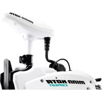
Riptide SP - Electric boat motor Minn Kota - Free user manual and instructions
Find the device manual for free Riptide SP Minn Kota in PDF.


User questions about Riptide SP Minn Kota
0 question about this device. Answer the ones you know or ask your own.
Ask a new question about this device
Download the instructions for your Electric boat motor in PDF format for free! Find your manual Riptide SP - Minn Kota and take your electronic device back in hand. On this page are published all the documents necessary for the use of your device. Riptide SP by Minn Kota.
USER MANUAL Riptide SP Minn Kota
text_image
minn.kota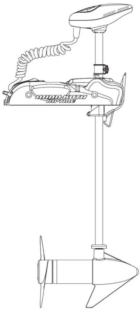
natural_image
Line drawing of a boat's main levers and propeller assembly (no text or symbols)RIPTIDE SP
BOW-MOUNT TROLLING MOTOR
USER MANUAL
CE MASTER USER MANUAL (FOR CE/C-TICK CERTIFIED MODELS)
Conforms to 89/336/EEC (EMC) under standards EN 55022A, EN 50082-2 since 1996 LN V9677264
THANK YOU
Thank you for choosing Minn Kota. We believe that you should spend more time fishing and less time positioning your boat. That's why we build the smartest, toughest, most intuitive trolling motors on the water. Every aspect of a Minn Kota trolling motor is thought out and rethought until it's good enough to bear our name. Countless hours of research and testing provide you the Minn Kota advantage that can truly take you "Anywhere. Anytime." We don't believe in shortcuts. We are Minn Kota. And we are never done helping you catch more fi sh.
REMEMBER TO KEEP YOUR RECEIPT AND IMMEDIATELY REGISTER YOUR TROLLING MOTOR.
A registration card is enclosed or you can complete registration on our website at minnkotamotors.com.
NOTE: Do not return your Minn Kota motor to your retailer. Your retailer is not authorized to repair or replace this unit. You may obtain service by: calling Minn Kota at (800) 227-6433; returning your motor to the Minn Kota Factory Service Center; sending or taking your motor to any Minn Kota authorized service center. A list of authorized service centers is available on our website, at minnkotamotors.com. Please include proof of purchase, serial number and purchase date for warranty service with any of the above options.
Please thoroughly read this user manual. Follow all instructions and heed all safety and cautionary notices below. Use of this motor is only permitted for persons that have read and understood these user instructions. Minors may use this motor only under adult supervision.
ATTENTION: Never run the motor out of the water, as this may result in injuries from the rotating propeller. The motor should be disconnected from the power source when it is not in use or is off the water. When connecting the power-supply cables of the motor to the battery, ensure that they are not kinked or subject to chafe and route them in such a way that persons cannot trip over them. Before using the motor make sure that the insulation of the power cables is not damaged. Disregarding these safety precautions may result in electric shorts of battery(s) and/or motor. Always disconnect motor from battery(s) before cleaning or checking the propeller. Avoid submerging the complete motor as water may enter the lower unit through control head and shaft. If the motor is used while water is present in the lower unit considerable damage to the motor can occur. This damage will not be covered by warranty.
CAUTION: Take care that neither you nor other persons approach the turning propeller too closely, neither with body parts nor with objects. The motor is powerful and may endanger or injure you or others. While the motor is running watch out for persons swimming and for floating objects. Persons whose ability to run the motor or whose reactions are impaired by alcohol, drugs, medication, or other substances are not permitted to use this motor. This motor is not suitable for use in strong currents. The constant noise pressure level of the motor during use is less than 70dB(A). The overall vibration level does not exceed 2.5m/sec2.
LOCATING YOUR SERIAL NUMBER
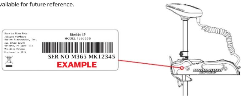
Your Minn Kota 11-character serial number is very important. It helps to determine the specific model and year of manufacture. When contacting Consumer Service or registering your product, you will need to know your product's serial number. We recommend that you write the serial number down in the space provided below so that you have it available for future reference.
The serial number on your Riptide SP is located inside the mount, below the motor rests.
text_image
available for future reference. Made by Main Power Jassava O'Alkouw Marine Electronics, Inc. 12L Power Draw Mystera, PK S&PY NBA Pociling Power Excluded at 012 Riptide SP MODEL 13635D SER NO M365 MK12345 EXAMPLEModel:
Serial Number:
Purchase Date:
Store Where Purchased:
TABLE OF CONTENTS
Two-Year Limited Warranty 4
Features 5-6
Mount Installation 7
Battery & Wiring Installation 8-9
Boat Rigging & Product Installation 8
Conductor Gauge and Circuit Breaker Sizing Table 8
Push-to-Test Battery Meter 8
Selecting the Correct Batteries 9
Connecting the Batteries 9
Motor Wiring Diagram 10
Using The Motor
11-13
Stowing & Deploying
11
Adjusting the Depth of the Motor
12
Installing an External Transducer
12
Using the CoPilot
13-15
General Operations
13
Remote Commands
13
Audio Modes
14
Adding/Removing Remotes
15
Replacing the Battery
15
Service & Maintenance
16
Propeller Replacement
16
General Maintenance
16
Troubleshooting & Repair
17-18
Environmental Compliance Statement
19
Parts Diagram
20
Parts List
21
TWO-YEAR LIMITED WARRANTY
WARRANTY ON MINN KOTA SALTWATER TROLLING MOTORS
Johnson Outdoors Marine Electronics, Inc. ("JOME") extends the following limited warranty to the original retail purchaser only. Warranty coverage is not transferable.
MINN KOTA LIMITED TWO-YEAR WARRANTY ON THE ENTIRE PRODUCT
JOME warrants to the original retail purchaser only that the purchaser's new Minn Kota saltwater trolling motor will be materially free from defects in materials and workmanship appearing within two (2) years after the date of purchase. JOME will (at its option) either repair or replace, free of charge, any parts found by JOME to be defective during the term of this warranty. Such repair, or replacement shall be the sole and exclusive liability of JOME and the sole and exclusive remedy of the purchaser for breach of this warranty.
MINN KOTA LIMITED LIFETIME WARRANTY ON COMPOSITE SHAFT
JOME warrants to the original retail purchaser only that the composite shaft of the purchaser's Minn Kota trolling motor will be materially free from defects in materials and workmanship appearing within the original purchaser's lifetime. JOME will provide a new composite shaft, free of charge, to replace any composite shaft found by JOME to be defective during the term of this warranty. Providing a new composite shaft shall be the sole and exclusive liability of JOME and the sole and exclusive remedy of the purchaser for breach of this warranty; and purchaser shall be responsible for installing, or for the cost of labor to install, any new composite shaft provided by JOME.
EXCLUSIONS & LIMITATIONS
This limited warranty does not apply to products that have been used commercially or for rental purposes. This limited warranty does not cover normal wear and tear, blemishes that do not affect the operation of the product, or damage caused by accidents, abuse, alteration, modification, shipping damages, acts of God, negligence of the user or misuse, improper or insufficient care or maintenance. DAMAGE CAUSED BY THE USE OF OTHER REPLACEMENT PARTS NOT MEETING THE DESIGN SPECIFICATIONS OF THE ORIGINAL PARTS WILL NOT BE COVERED BY THIS LIMITED WARRANTY. The cost of normal maintenance or replacement parts which are not in breach of the limited warranty are the responsibility of the purchaser. Prior to using products, the purchaser shall determine the suitability of the products for the intended use and assumes all related risk and liability. Any assistance JOME provides to or procures for the purchaser outside the terms, limitations or exclusions of this limited warranty will not constitute a waiver of the terms, limitations or exclusions, nor will such assistance extend or revive the warranty. JOME will not reimburse the purchaser for any expenses incurred by the purchaser in repairing, correcting or replacing any defective products or parts, except those incurred with JOME's prior written permission. JOME'S AGGREGATE LIABILITY WITH RESPECT TO COVERED PRODUCTS IS LIMITED TO AN AMOUNT EQUAL TO THE PURCHASER'S ORIGINAL PURCHASE PRICE PAID FOR SUCH PRODUCT.
MINN KOTA SERVICE INFORMATION
To obtain warranty service in the U.S., the product believed to be defective, and proof of original purchase (including the date of purchase), must be presented to a Minn Kota Authorized Service Center or to Minn Kota's factory service center in Mankato, MN. Any charges incurred for service calls, transportation or shipping/freight to/from the Minn Kota Authorized Service Center or factory, labor to haul out, remove, re-install or re-rig products removed for warranty service, or any other similar items are the sole and exclusive responsibility of the purchaser. Products purchased outside of the U.S. must be returned prepaid with proof of purchase (including the date of purchase and serial number) to any Authorized Minn Kota Service Center in the country of purchase. Warranty service can be arranged by contacting a Minn Kota Authorized Service Center or by contacting the factory at 1-800-227-6433 or email service@minnkotamotors.com.
Products repaired or replaced will be warranted for the remainder of the original warranty period [or for 90 days from the date of repair or replacement, whichever is longer]. For any product that is returned for warranty service that JOME finds to be not covered by or not in breach of this limited warranty, there will be a billing for services rendered at the prevailing posted labor rate and for a minimum of at least one hour.
NOTE: Do not return your Minn Kota product to your retailer. Your retailer is not authorized to repair or replace products.
THERE ARE NO EXPRESS WARRANTIES OTHER THAN THESE LIMITED WARRANTIES. IN NO EVENT SHALL ANY IMPLIED WARRANTIES INCLUDING ANY IMPLIED WARRANTIES OF MERCHANTABILITY OR FITNESS FOR PARTICULAR PURPOSE, EXTEND BEYOND THE DURATION OF THE RELEVANT EXPRESS LIMITED WARRANTY. IN NO EVENT SHALL JOME BE LIABLE FOR PUNITIVE, INDIRECT, INCIDENTAL, CONSEQUENTIAL OR SPECIAL DAMAGES. Without limiting the foregoing, JOME assumes no responsibility for loss of use of product, loss of time, inconvenience or other damage.
Some states do not allow limitations on how long an implied warranty lasts or the exclusion or limitation of incidental or consequential damages, so the above limitations and/or exclusions may not apply to you. This warranty gives you specific legal rights and you may also have other legal rights which vary from state to state.
FEATURES
text_image
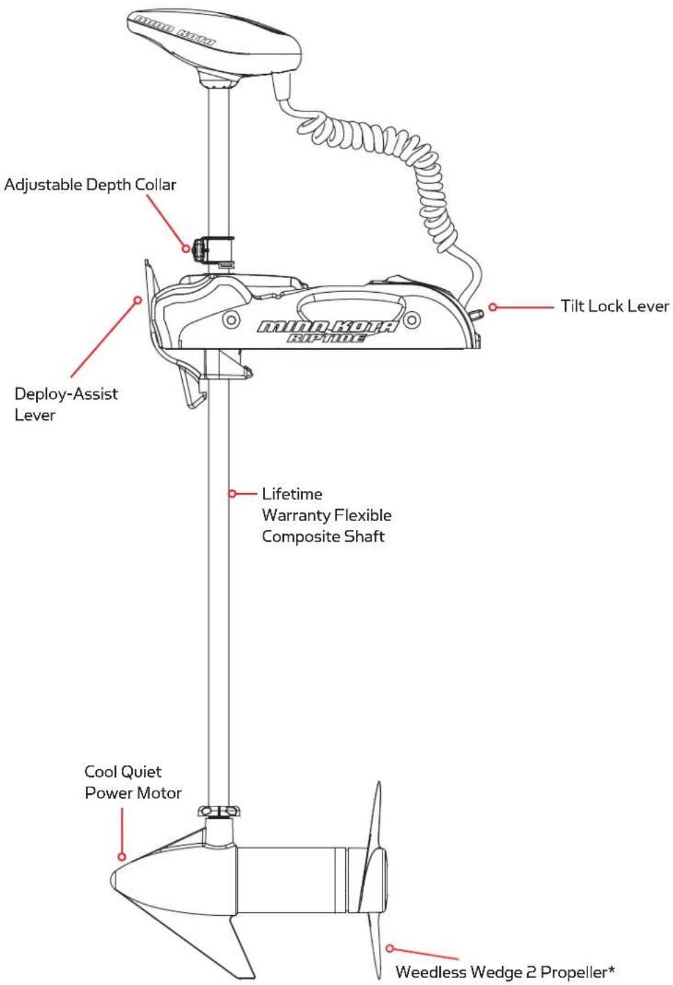
Adjustable Depth Collar Deploy-Assist Lever Tilt Lock Lever Lifetime Warranty Flexible Composite Shaft Cool Quiet Power Motor Weedless Wedge 2 Propeller*Specifications subject to change without notice.
*This diagram is for reference only and may differ from your actual motor.
FEATURES
COPILOT FEATURES\*
REMOTE
text_image
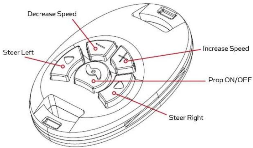
Decrease Speed Steer Left Increase Speed Prop ON/OFF Steer RightCOPILOT RECEIVER
text_image
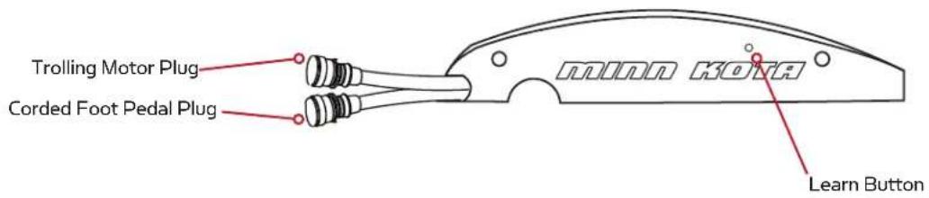
Trolling Motor Plug Corded Foot Pedal Plug minn kota Learn Button* For CoPilot equipped motors only.
MOUNT INSTALLATION
TOOLS AND RESOURCES REQUIRED:
• #3 Phillips Screw Driver
- Drill
- 9/32" Drill Bit
- 7/16" Box End Wrench
• A second person to help with the installation
- Remove the four sideplate screws. Remove the right sideplate and swing the left sideplate out and away from the base extrusion.
- Place the motor on the bow of the boat in the deployed position.
a. We recommend that the motor be mounted as close to the centerline of the boat as possible.
b. Make sure that the area under the mounting location is clear and unobstructed for drilling and accessible for you to attach nuts and washers.
c. Make sure the mount is positioned so that the shaft is out beyond the rub rail of the boat by 1-1/2". The lower unit, as it is lowered into the water or raised into the boat, must not encounter any obstructions.
CAUTION: Make sure the motor is mounted on a level surface and is not connected to a power source. Use the rubber washers to create a level surface if necessary.
- Once in position, mark four of the twelve holes (two on each side) provided in the bow mount base for drilling. If possible, use the four holes that are farthest apart. Drill through the marked holes using the 9/32" drill bit.
- Mount the plate to the bow using the provided bolts, nuts, and washers.
- Replace the sideplates and sideplate screws.

text_image
Mounting Holes (6 Per Side)BATTERY WIRING & INSTALLATION
BOAT RIGGING & PRODUCT INSTALLATION
For safety and compliance reasons, we recommend that you follow American Boat and Yacht Council (ABYC) standards when rigging your boat. Altering boat wiring should be completed by a qualified marine technician. The following specifications are for general guidelines only:
CAUTION: These guidelines apply to general rigging to support your Minn Kota motor. Powering multiple motors or additional electrical devices from the same power circuit may impact the recommended conductor gauge and circuit breaker size. If you are using wire longer than that provided with your unit, follow the conductor gauge and circuit breaker sizing table below. If your wire extension length is more than 25 feet, we recommend that you contact a qualified marine technician.
An over-current protection device (circuit breaker or fuse) must be used. Coast Guard requirements dictate that each ungrounded current-carrying conductor must be protected by a manually reset, trip-free circuit breaker or fuse. The type (voltage and current rating) of the fuse or circuit breaker must be sized accordingly to the trolling motor used. The table below gives recommended guidelines for circuit breaker sizing.
Reference:
United States Code of Federal Regulations: 33 CFR 183 – Boats and Associated Equipment
ABYC E-11: AC and DC Electrical Systems on Boats
CONDUCTOR GAUGE AND CIRCUIT BREAKER SIZING TABLE
| Motor Thrust / Model | Max Amp Draw | Circuit Breaker | Wire Extension Length * | ||||
| 5 feet 10 | feet 15 | feet 20 | feet 25 | feet | |||
| 30 lb. 30 | 50 Amp @ 12 VDCWG 4 AWG 4 AWG | 10 AWG 1 | 10 AWG 8 | WG 6 AWG | 4 AWG | ||
| 40 lb., 45 lb. 42 10 | AWG 8 AWG 6 AW | ||||||
| 50 lb., 55 lb. | 50 | 60 Amp @ 12 VDC | 8 AWG | 6 AWG | 4 AWG | 4 AWG | 2 AWG |
| 70 lb. | 42 | 50 Amp @ 24 VDC | 10 AWG | 10 AWG | 8 AWG | 8 AWG | 6 AWG |
| 80 lb. | 56 | 60 Amp @ 24 VDC | 8 AWG | 8 AWG | 8 AWG | 6 AWG | 6 AWG |
| 101 lb. | 46 | 50 Amp @ 36 VDC | 8 AWG | 8 AWG | 8 AWG | 8 AWG | 8 AWG |
| Engine Mount 101 | 50 | 60 Amp @ 36 VDC | 8 AWG | 6 AWG | 4 AWG | 4 AWG | 2 AWG |
| 112 lb. | 52 | 60 Amp @ 36 VDC | 8 AWG | 8 AWG | 8 AWG | 8 AWG | 8 AWG |
| Engine Mount 160 | 116 | (2) x 60 Amp @ 24 VDC | 2 AWG | 2 AWG | 2 AWG | 2 AWG | 2 AWG |
| E-Drive | 40 | 50 Amp @ 48 VDC | 10 AWG | 10 AWG | 10 AWG | 10 AWG | 10 AWG |
This conductor and circuit breaker sizing table is only valid for the following assumptions:
- No more than 3 conductors are bundled together inside of a sheath or conduit outside of engine spaces.
- Each conductor has 105^ C temp rated insulation.
- No more than 5% voltage drop allowed at full motor power based on published product power requirements.
*Wire Extension Length refers to the distance from the batteries to the trolling motor leads.
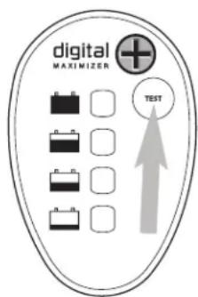
PUSH-TO-TEST BATTERY METER
This motor is equipped with a "push-to-test" battery meter. The LED provides an accurate display of the remaining charge in the battery. It is only accurate when the motor is off.
The meter reads as:
• One light indicates recharge.
- Two lights indicate low charge.
- Three lights indicate good charge.
- Four lights indicate full charge.
text_image
digital MAXIMIZER TESTSELECTING THE CORRECT BATTERIES
The motor will operate with any lead acid, deep cycle marine 12 volt battery/batteries. For best results, use a deep cycle, marine battery with at least a 105 ampere hour rating. Maintain battery at full charge. Proper care will ensure having battery power when you need it, and will significantly improve the battery life. Failure to recharge lead-acid batteries (within 12-24 hours) is the leading cause of premature battery failure. Use a multi-stage charger to avoid overcharging. We offer a wide selection of chargers to fit your charging needs. If you are using a crank battery to start a gasoline outboard, we recommend that you use a separate deep cycle marine battery/batteries for your Minn Kota trolling motor.
Advice Regarding Batteries:
- Never connect the (+) and the (−) terminals of the same battery together. Take care that no metal object can fall onto the battery and short the terminals. This would immediately lead to a short and extreme fire danger.
- It is highly recommended that a circuit breaker or fuse be used with this trolling motor. Refer to “Conductor Gauge and Circuit Breaker Sizing Table” in the previous section to find the appropriate circuit breaker or fuse for your motor. For motors requiring a 60-amp breaker, the Minn Kota MKR-19 60-amp circuit breaker is recommended.
CONNECTING THE BATTERIES
12 VOLT SYSTEMS:
- Make sure that the motor is switched off (speed selector on "OFF" or "O").
- Connect positive (+) red lead to positive (+) battery terminal.
- Connect negative (−) black lead to negative (−) battery terminal.
- For safety reasons do not switch the motor on until the propeller is in the water.
CAUTION:
For safety reasons, disconnect the motor from the battery/batteries when the motor is not in use or while the battery/batteries are being charged.
CONNECTING THE BATTERIES IN SERIES (IF REQUIRED FOR YOUR MOTOR)
24 VOLT SYSTEMS:
- Make sure that the motor is switched off (speed selector on "O").
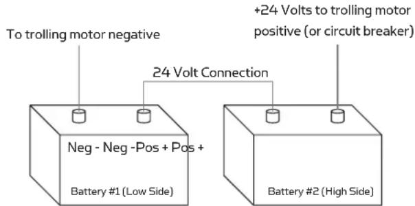
- Two 12 volt batteries are required.
- The batteries must be wired in series, only as directed in wiring diagram, to provide 24 volts.
a. Connect a connector cable to the positive (+) terminal of battery 1 and to the negative (−) terminal of battery 2.
b. Connect positive (+) red motor lead to positive (+) terminal on battery 2.
c. Connect negative (−) black motor lead to negative (−) terminal of battery 1.
text_image
To trolling motor negative Neg - Neg -Pos + Pos + Battery #1 (Low Side) 24 Volt Connection +24 Volts to trolling motor positive (or circuit breaker) Battery #2 (High Side)24 Volt Series Connection
- For safety reasons do not switch the motor on until the propeller is in the water. If installing a leadwire plug, observe proper polarity and follow instructions in your boat owner's manual. See wiring diagram on following pages.
CAUTION
- For safety reasons, disconnect the motor from the battery or batteries when the motor is not in use or while the battery/batteries are being charged.
- Improper wiring of 24/36 volt systems could cause battery explosion!
- Keep leadwire wing nut connections tight and solid to battery terminals.
- Locate battery in a ventilated compartment.
MOTOR WIRING DIAGRAM
NOTE: This is a universal, multi-voltage diagram. Double check your motor's voltage for proper connections. Over-Current Protection Devices not shown in this illustration.

text_image
AUTOPilot EQUIPPED MOTORS ONLY COMPASS SENSOR BOARD GREEN YELLOW BROWN RED BLACK YELLOW GREEN RED COIL CORD UNIVERSAL SONAR 2 EXTENSION WIRE* STEERING MOTOR CONTROL BOARD B- B+ RED BLACK M+ M- M- 12v BATTERY GAUGE FOOT PEDAL CONTROL BOARD* RED B+ BLACK B- BATTERY 1 24v BATTERY 2 BATTERY 3 *ON US2 EQUIPPED MOTORS ONLY RED M+ MOTORUSING & ADJUSTING THE MOTOR
STOWING AND DEPLOYING THE MOTOR
WARNING:
When raising or lowering the motor, keep fingers clear of all hinge and pivot points and all moving parts.
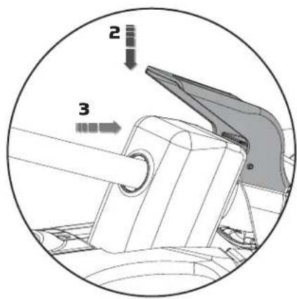
DEPLOY-ASSIST LEVER OPERATION:
- Loosen the depth collar screw.
- Push Deploy-Assist Lever down.
- Push motor out.
- Tighten the depth collar screw.
text_image
2 3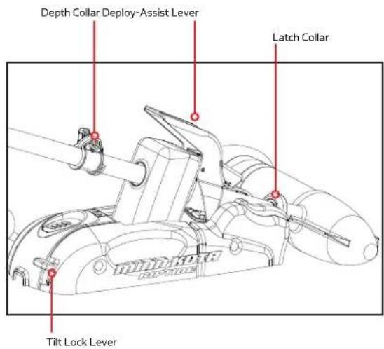
text_image
Depth Collar Deploy-Assist Lever Latch Collar Tilt Lock Lever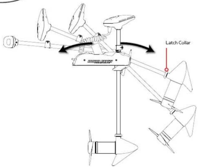
text_image
Latch CollarTO DEPLOY THE MOTOR
Loosen the Depth Collar screw, then push firmly down on the Deploy-Assist Lever to release the collar and slide the motor forward, out from the ramp. Lower the motor to the desired depth. Make sure it clicks into a secure, vertical position.
TO STOW THE MOTOR
Push down on the Tilt Lock Lever and raise the motor by pulling up on the composite shaft or control head. Pull the motor toward the stern until it rests securely on the ramp and the Deploy-Assist Lever captures the latch collar. Slide the depth collar down and secure it against the top of the steering housing to secure the motor in place and prevent accidental deployment.
TRANSPORTATION
In conditions where the stowed motor is subject to high levels of shock or vibration, take care to provide a secure stow. Move the depth collar snug against the steering motor and tighten.
TO ADJUST THE LATCH COLLAR
The latch collar is adjustable. If needed, loosen the Phillips head screw and rotate the collar up or down to re-align the latch and collar. The ideal adjustment is a slightly loose fit that completely captures the collar.
ADJUSTING THE DEPTH OF THE MOTOR
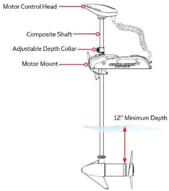
When setting the depth be sure the top of the motor is submerged at least 12" to avoid churning or agitation of surface water. The propeller must be completely submerged.
- With the motor deployed, firmly grasp the composite shaft above the mount.
- Loosen the adjustable depth collar until the shaft slides freely.
- Raise or lower the motor to the desired depth.
- Turn the motor control head to the desired position.
- Tighten adjustable depth collar to secure the motor in place.
text_image
Motor Control Head Composite Shaft Adjustable Depth Collar Motor Mount 12" Minimum DepthINSTALLING AN EXTERNAL TRANSDUCER
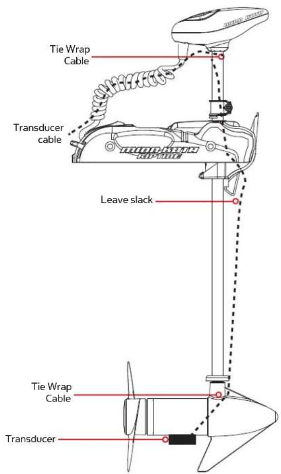
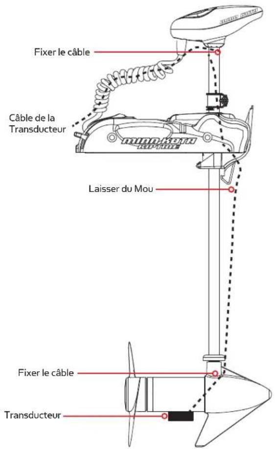
An external sonar transducer can be installed onto the motor as shown.
- Transducer cables should be routed through the coil cable as depicted in the illustration to the right.
- Leave enough slack for proper stow and deploy.
- Mount transducer according to transducer instructions.
Note: An external transducer is not included with your trolling motor. Your trolling motor may be pre-installed with a Universal Sonar 2 transducer system. In this case, the transducer is integrated into the motor unit.
For compatibility and more information on Universal Sonar 2, please visit minnkotamotors.com/us2.
ACCESSORY RECOMMENDATIONS:
• Minn Kota Transducer Mounting Kit (MKR-15)
text_image
Tie Wrap Cable Transducer cable Leave slack Tie Wrap Cable TransducerUSING THE COPILOT\*
GENERAL OPERATION
USING THE HAND REMOTE WITH THE CORDED FOOT PEDAL
- When the corded foot pedal's MOM-CON switch is in the CON position or when the Momentary On switch is held, the receiver WILL NOT RES POND to any remote commands. When remote commands are received, the receiver will emit an audio chirp. This will indicate that the remote is functioning properly although a corded foot pedal switch is active and is overriding the remote.
- When the MOM-CON switch is in the MOM position, the angler may begin using the remote at any time.
- As soon as any remote button is pressed, the initial speed setting will be approximately the same as the corded foot pedal's speed control position. However, the prop will not automatically turn on until the remote's prop on/off button is pressed.
- Pressing the corded foot pedal momentary switch or steering switches will override the remote and receiver function and control will automatically go to the corded foot pedal. The prop speed will also revert to the current position of the speed control on the corded foot pedal.
USING THE COPILOT WITHOUT THE CORDED FOOT PEDAL
- If the foot pedal is not being used, the CoPilot receiver will always react to any commands from the CoPilot remote.
REMOTE COMMANDS
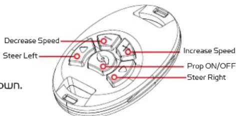
There are five buttons on your CoPilot:
- PROP ON/OFF
Turns the propeller on or off. Press the button once to turn the propeller ON; press button a second time to turn it OFF. The button does not need to be held down.
text_image
Decrease Speed Steer Left Increase Speed Prop ON/OFF Steer Right DOWN.• ST EER LEFT /ST EER RIGHT
Causes the motor to turn in the desired direction as long as the button is held down. If a steering button is held for more than seven seconds, the steering will automatically stop until the button is pressed again.
• INCREASE SPEED/DECREASE SPEED
Pressing and releasing these buttons causes the speed to increase or decrease by one level. The speed is adjustable from level 0-10. At level 0, the prop will not turn.
- In audio mode 2, an audible beep is heard for each step change in speed. Attempting to go higher than speed 10 or lower than speed 0 will result in the speed not changing and no beep will be heard. See the Audio Mode section for more information.
- If the receiver senses no foot pedal or remote operation for 1 hour, the remote speed setting is automatically set to zero. This helps prevent unintentional activation of the propeller if the PROP ON/OFF remote button is inadvertently pressed.
AUDIO MODES
There are three receiver audio modes available. The unit is factory set to Audio Mode 2. To switch from one audio mode to another, simultaneously press and hold the increase and decrease speed buttons for one second. The receiver will respond with 1, 2 or 3 audible beeps indicating the corresponding receiver audio mode change.
- Audio Mode 1 = All of the normal audible sounds mentioned in this owners manual, but no audible beeps for speed increase / decrease or prop on / off.
- Audio Mode 2 = Same as audio mode 1 plus an audible beep for speed increase / decrease and prop on/off.
- Audio Mode 3 = Same as audio mode 2 plus the prop on audible click every few seconds.
NOTE: When the corded foot pedal is in control and the propeller is on, the prop on indicator click will be heard if the receiver is set to audio mode 3.
| AUDIO PATTERN W | WHAT CONDITION CA USES IT OCCURS IN WHICH AUDIO MODE | |
| 1 Beep | Pressing the INCREASE SPEED or DECREASE SPEED button. | Modes 2 and 3 |
| 1 Beep Pressing the PROP ON/OFF button to turn the prop on. Modes 2 and 3 | ||
| 2 Beeps Pressing the PROP ON/OFF button to turn the prop off . Modes 2 and 3 | ||
| Single tick every 1.5 seconds | When the prop is active including when speed is set to 0. Mode 3 | |
| 1 Beep | Switching to audio mode 1 (pressing the INCREASE SPEED and DECREASE SPEED simultaneously for 1 second). | All |
| 2 Beeps | Switching to audio mode 2 (pressing the INCREASE SPEED and DECREASE SPEED simultaneously for 1 second). | All |
| 3 Beeps | Switching to audio mode 1 (pressing the INCREASE SPEED and DECREASE SPEED simultaneously for 1 second). | All |
| 1 Chirp | Every time the receiver is powered up and there is at least one remote ID learned. | All |
| 2 Second long beep | Every time the receiver is powered up and there are no remote IDs learned. | All |
| 5 Beeps | Foot pedal speed control is moved after speed has been adjusted with remote. | All |
| Steady tone | Heard while holding down the learn button on the receiver. | All |
| 4 Beeps | After a remote button is pressed while the receiver learns its ID. | All |
| Ten second warbling sound that transitions into a steady tone | Heard during the process used to clear all stored remote IDs. After the learn switch is released, a 2 second long beep will be heard. | All |
| 1 Long beep, 2 short beeps, pause (repeat) | Powered up with MOM/CON in the CON (or MOM switch held) when foot pedal is moved to momentary, the power up audio will be heard. | All |
ADDING/REMOVING REMOTES
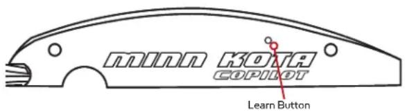
The CoPilot receiver in this kit has already “learned” the ID number of the remote it is packaged with. The receiver must “learn” the ID number of any additional remote(s) that you intend to use. When the receiver learns the ID number of a remote, that ID number is retained in the receiver even when the motor is disconnected from its power source.
text_image
minn KOTA COPILOT Learn ButtonTo "learn" the ID number of additional remotes, follow these steps:
- Press and hold the LEARN button located on the side of the receiver (receiver will emit a continuous tone). A small, blunt object such as a pen or screwdriver must be used to depress the LEARN button.
- Press any button on the remote (receiver will beep 4 times confirming that it has "learned" the ID number of the remote and that the programming is valid and complete.)
NOTE: "Re-learning" the ID number of the same remote will not overwrite previously "learned" remotes.
NOTE: If the receiver has “learned” the ID number of ten remotes, “learning” an eleventh remote will overwrite the first remote.
To erase all stored remote ID numbers from the receiver, follow these steps:
- Remove power from the receiver by unplugging the receiver from the motor.
- Press and hold the LEARN button and power up the receiver by plugging it back into the motor. Hold the LEARN button down for 10 seconds. During this time the receiver audio will emit a warble sound, slowly transition to a constant beep and then shut off.
- Release the LEARN button and the receiver will reboot. The receiver will emit a 2 second long beep indicating memory is empty. This audio pattern will occur each time the receiver powers up until a remote ID number is learned.
REPLACING THE BATTERY
- Temporarily ground yourself by touching a grounded metal object in order to discharge any static electricity in your body.
- Remove the four screws on the bottom of the remote case.
- Separate the case halves to access the circuit board.
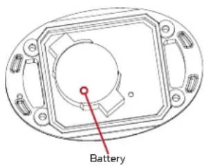
- Pull back the retaining fingers of the battery holder to remove the battery (underside of circuit board).
- Install the new battery with the positive (+) side of the battery facing up (away from the circuit board). Ensure battery is snapped securely in place.
- Reassemble the remote. Note that the alignment peg in the remote case must line up with the corresponding alignment hole in the circuit board. Also note that the keypad must be positioned so that the buttons are over the end of the circuit board opposite from the alignment peg and hole. Reinstall the four case screws and tighten them as required.
NOTE: The replacement battery must be a model cr2032 coin cell type. It is strongly recommended that a name brand battery is used.
text_image
Battery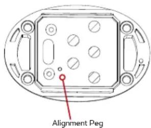
text_image
Alignment PegSERVICE & MAINTENANCE
PROPELLER REPLACEMENT
TOOLS AND RESOURCES REQUIRED:
- Box End Wrench
- 1/2" for motors with 70 lbs thrust or lower.
- 9/16" for motors with 80 lbs thrust or higher.
- Screwdriver (optional)
CAUTION:
Disconnect the motor from the battery before beginning any prop work or maintenance.
NOTE: The propeller on your motor may differ from the one pictured.

text_image
Propeller Anode/Nut Washer Drive Pin- Disconnect motor from battery prior to changing the propeller.
- Hold the propeller and loosen the anode/nut with a wrench.
- Remove anode/nut and washer. If the drive pin is sheared/broken, you will need to hold the shaft steady with a screwdriver blade pressed into the slot on the end of the shaft.
- Turn the old prop to horizontal (as illustrated) and pull it straight off. If drive pin falls out, push it back in.
- Align new propeller with drive pin.
- Install prop washer and anode/nut.
- Tighten anode/ nut 1/4 turn past snug. [25-35 inch lbs.] Be careful, over tightening can damage prop.
GENERAL MAINTENANCE
- After every use, the entire motor should be rinsed with freshwater, then wiped down with a cloth dampened with an aqueous based silicone spray.
- The propeller must be inspected and cleaned of weeds and fi shing line after every use. Fishing line and weeds can get behind the prop, damage the seals and allow water to enter the motor.
- Verify the prop nut is secure each time the motor is used.
- To prevent accidental damage during transportation or storage, disconnect the battery whenever the motor is off of the water. For prolonged storage, lightly coat all metal parts with an aqueous based silicone spray.
- For maximum battery life, recharge the battery(s) as soon as possible after use. For maximum motor performance, restore battery to full charge prior to use.
- Keep battery terminals clean with fine sandpaper or emery cloth.
- The propeller is designed to provide optimum operation with very high efficiency. To maintain this top performance, the leading edge of the blades must be kept smooth. If they are rough or nicked from use, restore to smooth by sanding with fine sandpaper.
TROUBLESHOOTING & REPAIR
TROUBLESHOOTING THE MOTOR
-
Motor fails to run or lacks power:
-
Check battery connections for proper polarity.
- Make sure terminals are clean and corrosion free. Use fine sandpaper or emery cloth to clean terminals.
-
Check battery water level. Add water if needed.
-
Motor loses power after a short running time:
- Check battery charge. If low, restore to full charge.
- You experience prop vibration during normal operation:
- Remove and rotate the prop 180^ . See removal instructions in the Propeller Replacement Section.
- Experiencing interference with your fi shfi nder:
- You may, in some applications, experience interference in your depth finder display. We recommend that you use a separate deep cycle marine battery for your trolling motor and that you power the depth finder from the starting/cranking battery. If problems still persist, call our service department at 1-800-227-6433.
NOTE: For any other malfunctions, visit an Authorized Service Center. You can search for an Authorized Service Center in your area by visiting our Authorized Service page, found online at minnkotamotors.com, or by calling our customer service number at 800-227-6433.
TROUBLESHOOTING THE COPILOT
| CAUSE EFFECT | SOLUTION | |
| Remote is not transmitting. | The battery is discharged. | Replace battery. |
| Receiver may not have "learned" the ID number of the remote. | Remote needs to be learned. See “Adding/Removing Remotes” to learn the remote ID number. | |
| With the foot pedal connected, the MOM-CON switch is in the CON position. An audio response will be heard if a button is pressed with the foot pedal in the CON position. | The foot pedal switch must be placed in the MOM position. The receiver will not accept any commands from the remote with the switch in the CON position. | |
| If remote has been taken apart, the keypad and top case may have been installed backwards. | Take remote apart (see “Replacing the Battery”) and reinstall case halves with the proper orientation. | |
| When receiver is powered up, it sounds a beep pattern (1 long beep, 2 short beeps, pause, repeat). | The foot pedal MOM-CON switch is in the CON position. | The foot pedal switch must be placed in the MOM position. The beeping sound will continue until the switch is placed in the MOM position. |
| The prop is not turning but the PROP ON audio tick is still going. | Prop Speed is set at "O". | Increase the prop speed above "O" |
| PROP ON tick occurs only in Audio Mode 3 | Switch Audio Mode to either Audio 1 or 2. See “Audio Modes”. |
FOR FURTHER TROUBLESHOOTING AND REPAIR
We offer several options to help you troubleshoot and/or repair your product. Please read through the options listed below.

QUENTLY ASKED QUESTIONS
We have FAQs available on our website to help answer all of your Minn Kota questions. Visit minnkotamotors.com and click on "Frequently Asked Questions" to find an answer to your question.

L US (FOR U.S. AND CANADA)
Our consumer service representatives are available Monday – Friday between 7:00 a.m. – 4:30 p.m. CST at 800-227-6433. If you are calling to order parts, please have the 11-character serial number from your product, specific part numbers, and credit card information available. This will help expedite your call and allow us to provide you with the best consumer service possible. You can reference the parts list located in your manual to identify the specific part numbers.

AIL US
You can email our consumer service department with questions regarding your Minn Kota products. To email your question, visit minnkotamotors.com and click on "Support".

THORIZED SERVICE CENTERS
Minn Kota has over 300 authorized service centers in the United States and Canada where you can purchase parts or get your products repaired. Please visit our Authorized Service Center page on our website to locate a service center in your area.
COMPLIANCE STATEMENTS
ENVIRONMENTAL COMPLIANCE STATEMENT:
It is the intention of JOME to be a responsible corporate citizen, operating in compliance with known and applicable environmental regulations, and a good neighbor in the communities where we make or sell our products.
WEEE DIRECTIVE:
EU Directive 2002/96/EC “Waste of Electrical and Electronic Equipment Directive (WEEE)” impacts most distributors, sellers, and manufacturers of consumer electronics in the European Union. The WEEE Directive requires the producer of consumer electronics to take responsibility for the management of waste from their products to achieve environmentally responsible disposal during the product life cycle.
WEEE compliance may not be required in your location for electrical & electronic equipment (EEE), nor may it be required
for EEE designed and intended as fixed or temporary installation in transportation vehicles such as automobiles, aircraft, and boats. In some European Union member states, these vehicles are considered outside of the scope of the Directive, and EEE for those applications can be considered excluded from the WEEE Directive requirement.
natural_image
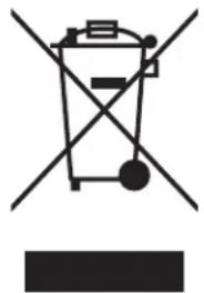
Simple line drawing of a trash bin with crossed lines indicating no waste or discharge (no text or symbols)This symbol (WEEE wheelie bin) on product indicates the product must not be disposed of with other household refuse. It must be disposed of and collected for recycling and recovery of waste EEE. Johnson Outdoors Inc. will mark all EEE products in accordance with the WEEE Directive. It is our goal to comply in the collection, treatment, recovery, and environmentally sound disposal of those products; however, these requirement do vary within European Union member states. For more information about where you should dispose of your waste equipment for recycling and recovery and/or your European Union member state requirements, please contact your dealer or distributor from which your product was purchased.
DISPOSAL:
Minn Kota motors are not subject to the disposal regulations EAG-VO (electric devices directive) that implements the WEEE directive. Nevertheless never dispose of your Minn Kota motor in a garbage bin but at the proper place of collection of your local town council.
Never dispose of battery in a garbage bin. Comply with the disposal directions of the manufacturer or his representative and dispose of them at the proper place of collection of your local town council.
WARNING: This product contains chemicals known to the State of California to cause cancer and birth defects or other reproductive harm.

CE
FCC ID: M05COPLT
IC: 4397A-M05COPLT
MODEL: COPILOT
The FCC and IC label can be found on the back side of the remote.
FCC AND INDUSTRY CANADA COMPLIANCE STATEMENT:
This device complies with FCC Rules Part 15 and Industry Canada RSS-210. Operation is subject to the following two conditions:
(1) This device may not cause harmful interference
(2) This device must accept any interference, including interference that may cause undesired operation of the device
Changes or modifications not expressly approved by the party responsible for compliance could void the user's authority to operate the equipment. Per FCC Part 15.21.
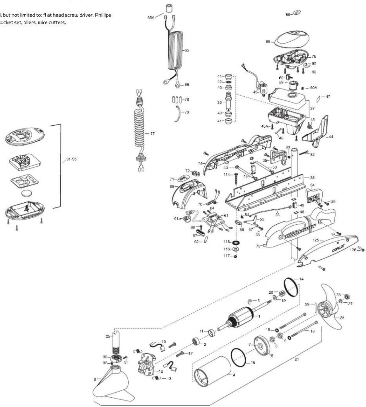
PARTS DIAGRAM
RIPTIDE SP 70
70 LBS THRUST - 24 VOLT - 54"/60" SHAFT
This page provides Minn Kota® WEEE compliance disassembly instructions. For more information about where you should dispose of your waste equipment for recycling and recovery and/or your European Union member state requirements, please contact your dealer or distributor from which your product was purchased.
Tools required, but not limited to: fl at head screw driver, Phillips screw driver, socket set, pliers, wire cutters.
text_image
i, but not limited to: fl at head screw driver, Phillips rocket set, pliers, wire cutters. 91-96 65A 65 66 78 79 77 41- 42- 40- 39- 40- 41- 43- 46A 46 89 86 76 80 90 60 59 60A 47 37 45 44 74 52 50 35 83 72 114 51 33 34 82 69 70 64 61 54 55 53 49 36 61a 68 67 62 56 57 58 73 125 75 126 14 20 19 1 3 29 28 27 25 30 32 31 10 17 11 2 7 8 9 18 15 16 4 21PARTS LIST
RIPTIDE SP 70
70 LBS THRUST - 24 VOLT - 54"/60" SHAFT
| ITEM | QTY | PART NUMBER | DESCRIPTION |
| 112 | 100-119 | ARMATURE AS | SY 24V |
| 211 | 40-010 | BALL BEARING | |
| 317 | 88-015 | RET AINING RING | |
| 412 | 200-304 | HOUSING AS | SY CENTER |
| 514 | 21-336 | HOUSING-B | RUSH END |
| 6 | 1 | 2-400-337 | PLAIN END HOUSING ASSEMBLY 3.625 |
| 7 | 1 | 144-049 | BEARING - FLANGE (SERVICE ONLY) |
| 81 | 880-003 | SEAL | |
| 9 | 1 | 880-006 | SEAL WITH SHIELD |
| 10 | 2 | 188-037 | BRUSH ASSEMBLY |
| 11 | 1 | 725-050 | BRUSH RETENTION- PAPER TUBE |
| 12 | 1 | 738-036 | BRUSH PLATE W/HOLDER |
| ■ | 1 | 2307314 | FERRITE BEAD |
| 13 | 2 | 975-040 | SPRING - TORSION |
| 14 | 1 | 337-036 | GASKET |
| 15 | 2 | 701-008 | O-RING, THRU-BOLT |
| 16 | 1 | 701-081 | O-RING |
| 17 | 2 | 830-007 | SCREW-8-32 |
| 18 | 2 | 830-042 | THRU-BOLT 10-32X8.83 |
| 19 | 1 | 990-067 | WASHER- STEEL THRUST |
| 20 | 2 | 990-070 | WASHER - NYLATRON |
| 21 | 12096056 MOTOR AS | SY 24V | |
| 25 | 1 | 2002000 | TUBE-48" WHITE |
| 1 | 2002001 TUBE-54" WHITE | ||
| 1 | 2002002 TUBE-60" WHITE | ||
| ■ | 1 | 1378131 | PROPELLER KIT |
| 26 | 1 | 2091160 | PROPELLER W/WEDGE 2 |
| 271 | 151726 | WAS HER-5/16 SS | |
| 28 | 1 | 2198400 | ZINC ANODE |
| 29 | 12092600 PIN-DRIVE | ||
| 30 | 1 | 2301545 | COLLAR- LATCH PD/AP |
| 31 | 1 | 2303434 | SCREW- 8-32X5/8 MACH |
| 321 | 303112 | NUT 8-32 NYLOC SS | |
| 33 | 1 | 2301937 | EXTRUSION- BASE MACH |
| 34 | 1 | 2303932 | MOTOR REST- RIGHT 3-5/8 |
| 35 | 1 | 2303937 | MOTOR REST- LEFT 3-5/8 |
| 36 | 4 | 2332104 | SCREW 1/4-20X5/8 |
| 37 | 1 | 2771827 | DRIVE HOUSING / LATCH HANDLE ASSY WHITE |
| ■ | 1 | 2882011 | BUSHING/ OUTSHAFT KIT (INCLUDES 39-42) |
| *39 | 1 | 2302010 | DRIVE HSNG OUTPUT SHFT |
| *40 | 2 | 2307304 | BUSHING- INNER |
| *41 | 2 | 2307305 | BUSHING- OUTER |
| *42 | 1 | 2304603 | O-RING |
| 43 | 1 | 2307050 | MOTOR- DRIVE HOUSING |
| 44 | 1 | 2307201 | LATCH HANDLE PD/AP |
| 45 | 1 | 2302750 | SPRING- LATCH TORSION |
| 46 | 1 | 2302628 | PIN- ROLL ZINC |
| 46A | 6 | 2303405 | SCREW - DRIVE HOUSING |
| 47 | 1 | 2305564 | DECAL-STOW/DEPLOY |
| 48 | 4 | 2305110 | PAD-PIVOT SUPT |
| 49 | 2 | 2305103 | PIVOT PAD- NEW MTR'L |
| 50 | 1 | 2300510 | PIN-LATCH |
| 51 | 12300520 PIN-PIVOT | ||
| 52 | 4 | 2013100 | NUT-SPEED |
| 53 | 1 | 2303612 | ROD-RELEASE RT/AP S |
| 54 | 1 | 2322700 | SPRING-RELEASE LEVER |
| 55 | 1 | 2333705 | LEVER-RELEASE |
| 56 | 1 | 2300101 | RELEASE-KNOB |
| 57 | 1 | 2301700 | SPACER-RELEASE LEVER |
| 58 | 1 | 2332104 | SCREW-1/4-20 X 5/8 |
| 59 | 1 | 2031522 | COLLAR- DRIVE(W/INSERT) |
| ITEM | QTY | PART NUMBER | DESCRIPTION |
| 60 | 1 | 2011366 | SCREW-COLLAR/NEW KNOB |
| 60A | 1 | 2323104 | NUT |
| 61 | 1 | 2304067 | CONTROL BOARD ASSEMBLY- 24V AP |
| 1 | 2304065 | CONTROL BOARD ASSEMBLY- 24V PD | |
| 61A | 1 | 2320208 | DUST COVER |
| 62 | 1 | 2355403 | SHRINK TUBE-3/8 ODX2 |
| 1 | 2355410 | SHRINK TUBE-3/8 ODX2 | |
| 64 | 3 | 2303434 | SCREW-8-32 X 5/8 |
| 65 | 1 | 2090651 | LEADWIRE LOGA 44" |
| 65A | 1 | 2307310 | BEAD - FERRITE (CE MODELS ONLY) |
| 66 | 2 | 2020700 | TERMINAL RING |
| 67 | 1 | 2321310 | STRAIN RELIEF- BRACKET PD/AP |
| 68 | 1 | 2323405 | SCREW-1/4-20 X 5/8 AUTOPILOT |
| 1 | 2322104 | SCREW-1/4-20 X 5/8 POWERDRIVE | |
| 69 | 1 | 2306556 | HOUSING- CENTER WHITE |
| 70 | 1 | 2074081 | BATTERY GAUGE - 24V |
| 71 | 1 | 2316606 | DECAL, BATTERY GAUGE |
| 72 | 1 | 2302935 | STRAIN RELIEF-DR. HSING |
| 73 | 1 | 2303944 | SIDEPLATE (RIGHT) WHITE |
| 74 | 1 | 2303949 | SIDEPLATE (LEFT) WHITE |
| 75 | 4 | 2332104 | SCREW-1/4-20 X 5/8 |
| 76 | 1 | 2302516 | CONTROL BOX PD/AP |
| 77 | 1 | 2991280 | COIL CORD WSTRAIN RELIEF POWERDRIVE |
| 78 | 3 | 2065400 | WIRE INSULATOR-LGE 1-3/4 |
| 79 | 1 | 2256300 | TIE WRAP-5" BLACK |
| 80 | 1 | 2224703 | INSERT- PLUG |
| 82 | 1 | 2332102 | SCREW-10-24 X 1-3/4 PPH Z/P |
| 83 | 1 | 2013101 | NUT-HEX 10-24 NYLOC |
| 85 | 3 | 2302960 | COMPASS GROMMET AUTOPILOT |
| 86 | 1 | 2300243 | CONTROL BOX COVER- RIPTIDE WHITE |
| 89 | 1 | 2315656 | DECAL- COVER 70PD |
| 1 | 2315690 | DECAL- COVER 70PD/AP | |
| 90 | 4 | 2012100 | SCREW-8-18 X 5/8 |
| ■ | 1 2994020 COPILOT | TRANSMITTER | |
| 91 | 1 | TRANSMITTER CASE CVR | |
| 92 | 1 | KEYPAD | |
| 93 | 1 | CIRCUIT BOARD, TRANS | |
| 94 | 1 | BATTERY, COIN | |
| 95 | 1 | TRANSMITTER CASE BTM | |
| 96 | 4 | SCREW, TRANSMITTER | |
| ■ | 1 | 2994089 | RECEIVER ASSEMBLY V2, COPILOT |
| 100 | 1 | 2372511 | CASE, RECEIVER WHT |
| 101 | 2 | 2373442 | SCREW 1/4-20 X 1.75 SS |
| 102 | 2 | 2373450 | SCREW #8 X 3/8 |
| 103 | 2 | 2371727 | WASHER |
| 104 | 1 | 2373418 | SCREW #8 X 5/8 SS |
| 105 | 1 | 2374092 | CIRCUIT BRD V2, RCVR AUTOPILOT |
| 1 | 2374089 | CIRCUIT BRD V2, RCVR POWERDRIVE | |
| ■ | 1 | 2994864 | BAG ASSEMBLY- (BOLT,NUT,WASHERS) |
| *114 | 6 | 2263462 | BOLT-MOUNTING-1/4X2 |
| *116 | 6 | 2261713 | WASHER-1/4 |
| *117 | 6 | 2263103 | NUT NYLOK 1/4-20 MTG |
| *118 | 6 | 2301720 | WASHER-MOUNTING RUBBER |
| ■ | 1 28 38460 SEAL & ORING KIT | ||
| 125 | 1 | 2774089 | COPILOT SIDEPLATE |
| 126 | 2 | 2373442 | SCREW -1/4-20 X 1.75 PPH MACH |
■ THIS ITEM IS PART OF AN ASSEMBLY.
*THIS ITEM IS PART OF A KIT AND ONLY LISTED FOR VIEWING PURPOSES.
RECOMMENDED ACCESSORIES
ON-BOARD & PORTABLE BATTERY CHARGERS
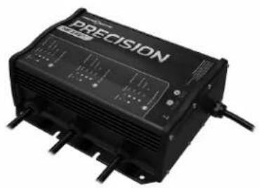
Stop buying new batteries and start taking care of the ones you've got. Many chargers can actually damage your battery over time – creating shorter run times and shorter overall life. Digitally controlled Minn Kota chargers are designed to provide the fastest charge that protect and extend battery life.
natural_image
Black precision electronic device with visible ports and wiring (no readable text or symbols)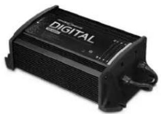
natural_image
Black digital audio recording device with no visible text or symbols on body
natural_image
Black industrial electrical clamp device with coiled wires (no visible text or symbols)MK210DMK345PC MKI10P
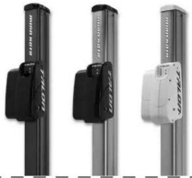
TALON SHALLOW WATER ANCHOR
Talon deploys faster, holds stronger and runs quieter than any other shallow water anchor. Available in depths up to 12' and bold color options, it boasts an arsenal of features and innovations that no other anchor can touch:
natural_image
Three vertical metal bars with black and white labels, no visible text or symbols on the bars themselves.• Vertical, Multi-Stage Deployment
- User-Selectable Anchoring Modes
- 2x Anchoring Force
- Fast Deploy
- Auto Up/Down
- Triple Debris Shields*
• Built-In Wave Absorption - Noise Dissipation
- Versatile Adjustments
*available on 10' and 12' models only
MINN KOTA ACCESSORIES
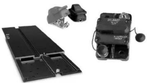
We offer a wide variety of trolling motor accessories, including:
natural_image
Exterior view of a black electronic device with a hand holding a small component and a close-up of its internal structure (no visible text or symbols)- 60-Amp Circuit Breaker
- Mounting Brackets
- Stabilizer Kits
-
Extension Handles
-
Battery Connectors
- Battery Boxes
- Quick Connect Plugs
For a complete listing of Minn Kota accessories, visit minnkotamotors.com
Follow us:


minnkotamotors.com
Minn Kota Consumer & Technical Service
Johnson Outdoors Marine Electronics, Inc.
PO Box 8129
Mankato, MN 56001
121 Power Drive
Mankato, MN 56001
Phone (800) 227-6433
Fax (800) 527-4464

©2015 Johnson Outdoors Marine Electronics, Inc.
All rights reserved.
text_image
minn.kota®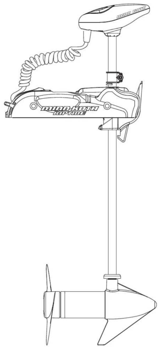
natural_image
Line drawing of a boat's main leaping device with coiled cable and propeller (no text or symbols)RIPTIDE SP
MOTEUR DE PÊCHE À LA TRAÎNE MONTÉ SUR L'ÉTRAVE
MANUEL DE L'UTILISATEUR
MANUEL CE D'UN MASTER (CE/C-TICK CERTIFIED MODELS)
natural_image
Technical line drawing of a mechanical device with a coiled cable and attached sensor (no text or symbols)Modèle :
Numéro de série :
Date de l'achat :
EXCLUSIONS & LIMITATIONS
INFORMATION SUR LE SERVICE MINN KOTA
text_image
Verrou CollierDÉPLOIEMENT
• Minn Kota Transducer Mounting Kit (MKR-15)
USING THE HAND REMOTE WITH THE CORDED FOOT PEDAL
DÉCLARATION DE CONFORMITÉ
DÉCLARATION DE CONFORMITÉ ENVIRONNEMENTALE
natural_image
Black precision electronic device with visible ports and control panel (no readable text or symbols)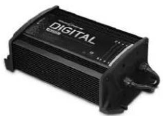
natural_image
Black digital audio recording device with visible grille and buttons (no text or symbols on body)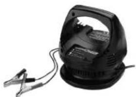
natural_image
Black industrial electrical clamp device with attached wires (no visible text or symbols)MK210DMK345PC MKI10P
natural_image
Three vertical cylindrical electronic components with black and white modules, no visible text or symbolsACCESSOIRES MINN KOTA
natural_image
Exterior view of a battery pack and its internal circuit board (no visible text or symbols)Minn Kota Consumer & Technical Service Johnson Outdoors Marine Electronics, Inc. PO Box 8129
Mankato, MN 56001
121 Power Drive
Mankato, MN 56001
Phone (800) 227-6433
Fax (800) 527-4464

©2015 Johnson Outdoors Marine Electronics, Inc. All rights reserved.