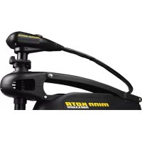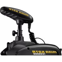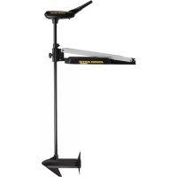
Edge Edge 45 - Electric boat motor Minn Kota - Free user manual and instructions
Find the device manual for free Edge Edge 45 Minn Kota in PDF.


Frequently Asked Questions - Edge Edge 45 Minn Kota
User questions about Edge Edge 45 Minn Kota
0 question about this device. Answer the ones you know or ask your own.
Ask a new question about this device
Download the instructions for your Electric boat motor in PDF format for free! Find your manual Edge Edge 45 - Minn Kota and take your electronic device back in hand. On this page are published all the documents necessary for the use of your device. Edge Edge 45 by Minn Kota.
USER MANUAL Edge Edge 45 Minn Kota
natural_image
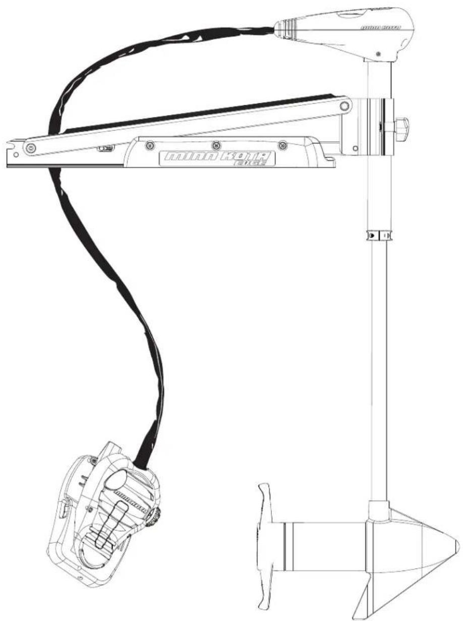
Technical line drawing of a mechanical device with attached cable and base mount (no text or symbols)EDGE
BOW-MOUNT TROLLING MOTOR
USER MANUAL
CE MASTER USER MANUAL (FOR CE/C-TICK CERTIFIED MODELS)
Conforms to 89/336/EEC (EMC) under standards EN 55022A, EN 50082-2 since 1996 LN V9677264
THANK YOU
Thank you for choosing Minn Kota. We believe that you should spend more time fishing and less time positioning your boat. That's why we build the smartest, toughest, most intuitive trolling motors on the water. Every aspect of a Minn Kota trolling motor is thought out and rethought until it's good enough to bear our name. Countless hours of research and testing provide you the Minn Kota advantage that can truly take you "Anywhere. Anytime." We don't believe in shortcuts. We are Minn Kota. And we are never done helping you catch more fi sh.
REMEMBER TO KEEP YOUR RECEIPT AND IMMEDIATELY REGISTER YOUR TROLLING MOTOR.
A registration card is enclosed or you can complete registration on the internet at minnkotamotors.com.
NOTE: Do not return your Minn Kota motor to your retailer. Your retailer is not authorized to repair or replace this unit. You may obtain service by: calling Minn Kota at (800) 227-6433; returning your motor to the Minn Kota Factory Service Center; sending or taking your motor to any Minn Kota authorized service center. A list of authorized service centers is available on our website, at minnkotamotors.com. Please include proof of purchase, serial number and purchase date for warranty service with any of the above options.
Please thoroughly read this user manual. Follow all instructions and heed all safety and cautionary notices below. Use of this motor is only permitted for persons that have read and understood these user instructions. Minors may use this motor only under adult supervision.
ATTENTION: Never run the motor out of the water, as this may result in injuries from the rotating propeller. The motor should be disconnected from the power source when it is not in use or is off the water. When connecting the power-supply cables of the motor to the battery, ensure that they are not kinked or subject to chafe and route them in such a way that persons cannot trip over them. Before using the motor make sure that the insulation of the power cables is not damaged. Disregarding these safety precautions may result in electric shorts of battery(s) and/or motor. Always disconnect motor from battery(s) before cleaning or checking the propeller. Avoid submerging the complete motor as water may enter the lower unit through control head and shaft. If the motor is used while water is present in the lower unit considerable damage to the motor can occur. This damage will not be covered by warranty.
CAUTION: Take care that neither you nor other persons approach the turning propeller too closely, neither with body parts nor with objects. The motor is powerful and may endanger or injure you or others. While the motor is running watch out for persons swimming and for floating objects. Persons whose ability to run the motor or whose reactions are impaired by alcohol, drugs, medication, or other substances are not permitted to use this motor. This motor is not suitable for use in strong currents. The constant noise pressure level of the motor during use is less than 70dB(A). The overall vibration level does not exceed 2.5m/sec2.
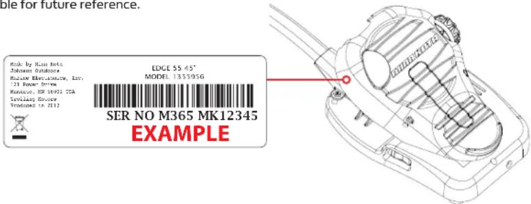
LOCATING YOUR SERIAL NUMBER
Your Minn Kota 11-character serial number is very important. It helps to determine the specific model and year of manufacture. When contacting Consumer Service or registering your product, you will need to know your product's serial number. We recommend that you write the serial number down in the space provided below so that you have it available for future reference.
The serial number on your Edge is located near the momentary switch underneath the side of the foot pedal.
text_image
Rook by Runi Rota Johnson Outdoors Marine Electronics, Inc. 121 Radar Drive Manique, NR 16931 TSA Tovilary Review Provoiced to 2012 EDCE 55.45" MODEL 135595G SER NO M365 MK12345 EXAMPLEModel:
Serial Number:
Purchase Date:
Store Where Purchased:
TABLE OF CONTENTS
Two-Year Limited Warranty 4
Features 5
Mount Installation 6-7
Battery & Wiring Installation 8-9
Boat Rigging & Product Installation 8
Conductor Gauge and Circuit Breaker Sizing Table 8
Selecting the Correct Batteries 9
Connecting the Batteries 9
Motor Wiring Diagram 10
Using & Adjusting The Motor 11-13
Stowing & Deploying the Motor 11
Adjusting the Depth of the Motor 12
Adjusting the Steering Cable 12
Controlling Speed and Steering with the Foot Pedal 13
Service & Maintenance 14
Propeller Replacement 14
General Maintenance 14
Troubleshooting & Repair 15
Parts Diagram 16
Parts List 17
Environmental Compliance Statement 18
Notes 19
TWO-YEAR LIMITED WARRANTY
WARRANTY ON MINN KOTA FRESHWATER TROLLING MOTORS
Johnson Outdoors Marine Electronics, Inc. ("JOME") extends the following limited warranty to the original retail purchaser only. Warranty coverage is not transferable.
MINN KOTA LIMITED TWO-YEAR WARRANTY ON THE ENTIRE PRODUCT
JOME warrants to the original retail purchaser only that the purchaser's new Minn Kota freshwater trolling motor will be materially free from defects in materials and workmanship appearing within two (2) years after the date of purchase. JOME will (at its option) either repair or replace, free of charge, any parts found by JOME to be defective during the term of this warranty. Such repair, or replacement shall be the sole and exclusive liability of JOME and the sole and exclusive remedy of the purchaser for breach of this warranty.
MINN KOTA LIMITED LIFETIME WARRANTY ON COMPOSITE SHAFT
JOME warrants to the original retail purchaser only that the composite shaft of the purchaser's Minn Kota trolling motor will be materially free from defects in materials and workmanship appearing within the original purchaser's lifetime. JOME will provide a new composite shaft, free of charge, to replace any composite shaft found by JOME to be defective during the term of this warranty. Providing a new composite shaft shall be the sole and exclusive liability of JOME and the sole and exclusive remedy of the purchaser for breach of this warranty; and purchaser shall be responsible for installing, or for the cost of labor to install, any new composite shaft provided by JOME.
EXCLUSIONS & LIMITATIONS
This limited warranty does not apply to products that have been used in saltwater or brackish water, commercially or for rental purposes. This limited warranty does not cover normal wear and tear, blemishes that do not affect the operation of the product, or damage caused by accidents, abuse, alteration, modification, shipping damages, acts of God, negligence of the user or misuse, improper or insufficient care or maintenance. DAMAGE CAUSED BY THE USE OF OTHER REPLACEMENT PARTS NOT MEETING THE DESIGN SPECIFICATIONS OF THE ORIGINAL PARTS WILL NOT BE COVERED BY THIS LIMITED WARRANTY. The cost of normal maintenance or replacement parts which are not in breach of the limited warranty are the responsibility of the purchaser. Prior to using products, the purchaser shall determine the suitability of the products for the intended use and assumes all related risk and liability. Any assistance JOME provides to or procures for the purchaser outside the terms, limitations or exclusions of this limited warranty will not constitute a waiver of the terms, limitations or exclusions, nor will such assistance extend or revive the warranty. JOME will not reimburse the purchaser for any expenses incurred by the purchaser in repairing, correcting or replacing any defective products or parts, except those incurred with JOME's prior written permission. JOME'S AGGREGATE LIABILITY WITH RESPECT TO COVERED PRODUCTS IS LIMITED TO AN AMOUNT EQUAL TO THE PURCHASER'S ORIGINAL PURCHASE PRICE PAID FOR SUCH PRODUCT.
MINN KOTA SERVICE INFORMATION
To obtain warranty service in the U.S., the product believed to be defective, and proof of original purchase (including the date of purchase), must be presented to a Minn Kota Authorized Service Center or to Minn Kota's factory service center in Mankato, MN. Any charges incurred for service calls, transportation or shipping/freight to/from the Minn Kota Authorized Service Center or factory, labor to haul out, remove, re-install or re-rig products removed for warranty service, or any other similar items are the sole and exclusive responsibility of the purchaser. Products purchased outside of the U.S. must be returned prepaid with proof of purchase (including the date of purchase and serial number) to any Authorized Minn Kota Service Center in the country of purchase. Warranty service can be arranged by contacting a Minn Kota Authorized Service Center or by contacting the factory at 1-800-227-6433 or email service@minnkotamotors.com.
Products repaired or replaced will be warranted for the remainder of the original warranty period [or for 90 days from the date of repair or replacement, whichever is longer]. For any product that is returned for warranty service that JOME finds to be not covered by or not in breach of this limited warranty, there will be a billing for services rendered at the prevailing posted labor rate and for a minimum of at least one hour.
NOTE: Do not return your Minn Kota product to your retailer. Your retailer is not authorized to repair or replace products.
THERE ARE NO EXPRESS WARRANTIES OTHER THAN THESE LIMITED WARRANTIES. IN NO EVENT SHALL ANY IMPLIED WARRANTIES INCLUDING ANY IMPLIED WARRANTIES OF MERCHANTABILITY OR FITNESS FOR PARTICULAR PURPOSE, EXTEND BEYOND THE DURATION OF THE RELEVANT EXPRESS LIMITED WARRANTY. IN NO EVENT SHALL JOME BE LIABLE FOR PUNITIVE, INDIRECT, INCIDENTAL, CONSEQUENTIAL OR SPECIAL DAMAGES. Without limiting the foregoing, JOME assumes no responsibility for loss of use of product, loss of time, inconvenience or other damage.
Some states do not allow limitations on how long an implied warranty lasts or the exclusion or limitation of incidental or consequential damages, so the above limitations and/or exclusions may not apply to you. This warranty gives you specific legal rights and you may also have other legal rights which vary from state to state.
FEATURES
text_image
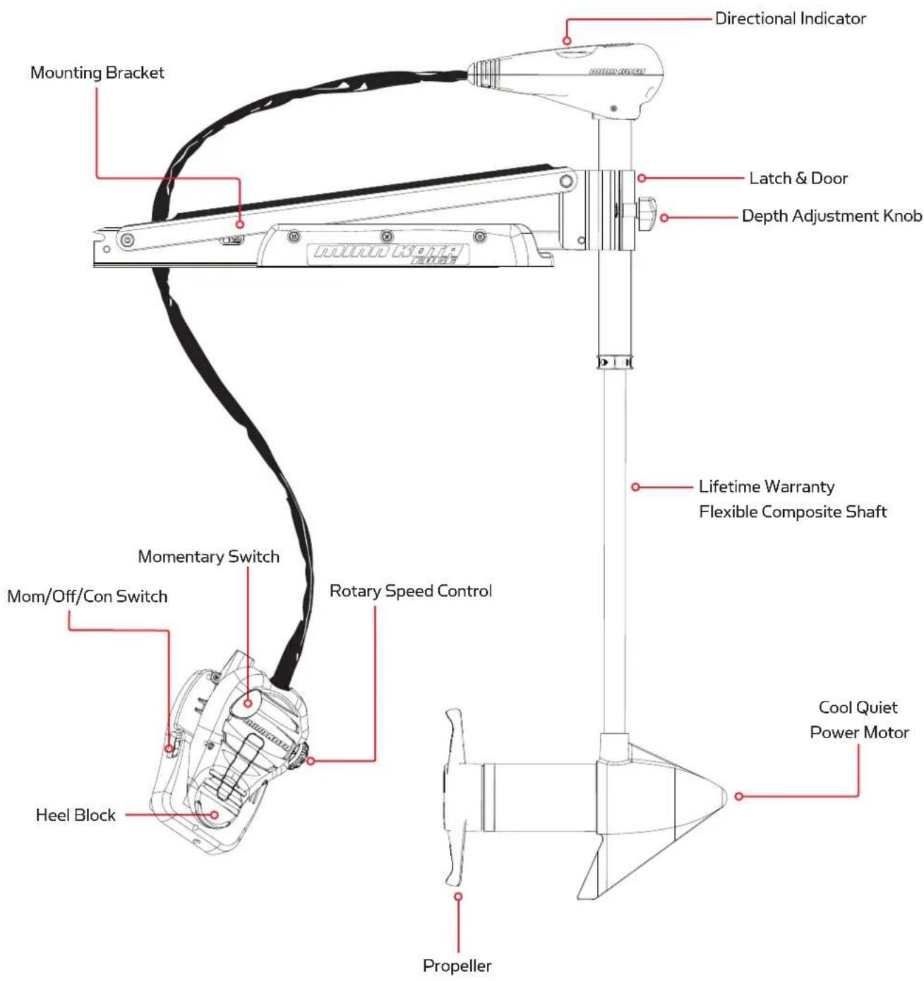
Mounting Bracket Momentary Switch Mom/Off/Con Switch Heel Block Rotary Speed Control Directional Indicator Latch & Door Depth Adjustment Knob Lifetime Warranty Flexible Composite Shaft Cool Quiet Power Motor PropellerSpecifications subject to change without notice.
*This diagram is for reference only and may differ from your actual motor.
MOUNT INSTALLATION
TOOLS AND RESOURCES REQUIRED:
• Phillips Screw Driver
- Drill
- 9/32" Drill Bit
- 7/16" Box End Wrench
• A second person to help with the installation
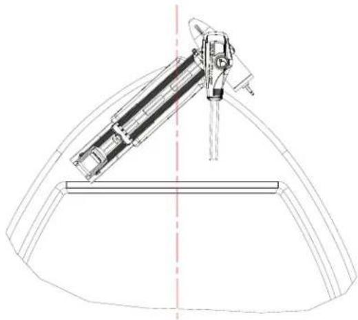
- Before you proceed, determine the desired mounting location for the motor. It is recommended that the motor be mounted as close to the center line of the boat as possible as seen below.
CAUTION: Make sure the motor is mounted on a level surface and is not connected to a power source.
natural_image
Technical line drawing of a mechanical device with a central shaft and support structure (no text or symbols)- Verify the area under the chosen mounting location is clear and safe to drill through.
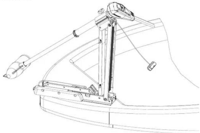
- Place the motor on top of the desired mounting location while it is in the stowed position (for stow and deploy instructions, see "Stowing and Deploying the Motor" on p. 11).
- Verify the motor rest is positioned far enough beyond the edge of the boat so that the motor clears all obstructions while deploying and stowing the motor.
natural_image
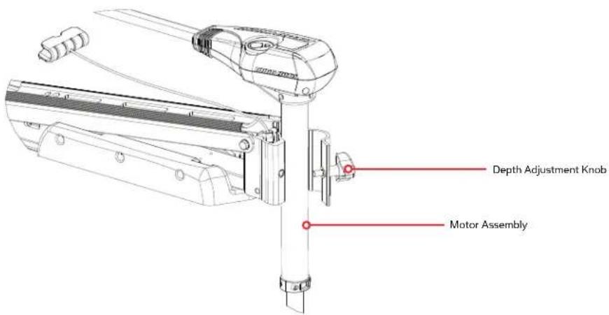
Technical line drawing of a mechanical linkage assembly (no text or symbols)- Deploy the motor and remove the motor assembly from the mount by loosening the Steering Tension Knob and opening the door.
WARNING:
When raising or lowering motor, keep fingers clear of all hinge and pivot points and all moving parts.
text_image
Depth Adjustment Knob Motor Assembly-
Position the mount again in the stowed position.
-
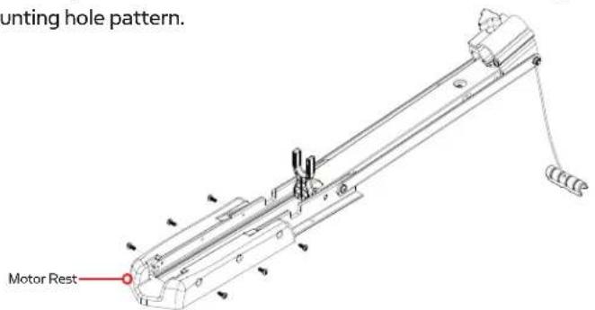
Temporarily remove the Phillips screws that fasten the motor rest to the mounting bracket and remove the motor rest to expose the motor mounting hole pattern.
text_image
Mounting hole pattern. Motor Rest-
Determine the mounting hole pattern you wish to use from the illustration to the right. Using the mounting holes in the mount as your template, mark the top deck of the boat with a pencil or an erasable marker.
-
Remove the mount from the deck of the boat and drill the holes that you marked in the previous step using a 9/32" drill bit and drill. Be careful not to damage any wiring or critical features that may exist under the surface you are drilling through.
-
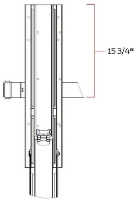
Place the mount on the deck of the boat again and verify the hold down strap is positioned 1534 " from the front of the bow mount as shown in the diagram.
-
Fasten the mount to the deck of the boat using the supplied 14 " – 20 X 2" bolts, washers and nuts. Tighten the stainless mount hardware securely but slowly to the deck of the boat using a 7/16" box end wrench. Tightening the stainless hardware too fast may result in galling and or seizing of the bolts and nuts.
-
Reinstall the motor rest using the six original 1/4" Phillips screws.
-
Reinstall the motor assembly into the mount and securely tighten the steering tension knob.
text_image
15 3/4"BATTERY WIRING & INSTALLATION
BOAT RIGGING & PRODUCT INSTALLATION
For safety and compliance reasons, we recommend that you follow American Boat and Yacht Council (ABYC) standards when rigging your boat. Altering boat wiring should be completed by a qualified marine technician. The following specifications are for general guidelines only:
CAUTION: These guidelines apply to general rigging to support your Minn Kota motor. Powering multiple motors or additional electrical devices from the same power circuit may impact the recommended conductor gauge and circuit breaker size. If you are using wire longer than that provided with your unit, follow the conductor gauge and circuit breaker sizing table below. If your wire extension length is more than 25 feet, we recommend that you contact a qualified marine technician.
An over-current protection device (circuit breaker or fuse) must be used. Coast Guard requirements dictate that each ungrounded current-carrying conductor must be protected by a manually reset, trip-free circuit breaker or fuse. The type (voltage and current rating) of the fuse or circuit breaker must be sized accordingly to the trolling motor used. The table below gives recommended guidelines for circuit breaker sizing.
Reference:
United States Code of Federal Regulations: 33 CFR 183 – Boats and Associated Equipment
ABYC E-11: AC and DC Electrical Systems on Boats
CONDUCTOR GAUGE AND CIRCUIT BREAKER SIZING TABLE
| Motor Thrust / Model | Max Amp Draw | Circuit Breaker | Wire Extension Length * | ||||
| 5 feet 10 feet 15 feet 20 feet 25 feet | |||||||
| 30 lb. 30 | 50 Amp @ 12 VDCWG 4 AWG 4 AWG | 10 AWG 10 AWG 8 AWG 6 AWG | |||||
| 40 lb., 45 lb. 42 10 | AWG 8 AWG 6 AW | ||||||
| 50 lb., 55 lb. | 50 | 60 Amp @ 12 VDC | 8 AWG | 6 AWG | 4 AWG | 4 AWG | 2 AWG |
| 70 lb. | 42 | 50 Amp @ 24 VDC | 10 AWG | 10 AWG | 8 AWG | 8 AWG | 6 AWG |
| 80 lb. | 56 | 60 Amp @ 24 VDC | 8 AWG | 8 AWG | 8 AWG | 6 AWG | 6 AWG |
| 101 lb. | 46 | 50 Amp @ 36 VDC | 8 AWG | 8 AWG | 8 AWG | 8 AWG | 8 AWG |
| Engine Mount 101 | 50 | 60 Amp @ 36 VDC | 8 AWG | 6 AWG | 4 AWG | 4 AWG | 2 AWG |
| 112 lb. | 52 | 60 Amp @ 36 VDC | 8 AWG | 8 AWG | 8 AWG | 8 AWG | 8 AWG |
| Engine Mount 160 | 116 | (2) x 60 Amp @ 24 VDC | 2 AWG | 2 AWG | 2 AWG | 2 AWG | 2 AWG |
| E-Drive | 40 | 50 Amp @ 48 VDC | 10 AWG | 10 AWG | 10 AWG | 10 AWG | 10 AWG |
This conductor and circuit breaker sizing table is only valid for the following assumptions:
- No more than 3 conductors are bundled together inside of a sheath or conduit outside of engine spaces.
- Each conductor has 105^ C temp rated insulation.
- No more than 5% voltage drop allowed at full motor power based on published product power requirements.
*Wire Extension Length refers to the distance from the batteries to the trolling motor leads.
SELECTING THE CORRECT BATTERIES
The motor will operate with any lead acid, deep cycle marine 12 volt battery/batteries. For best results, use a deep cycle, marine battery with at least a 105 ampere hour rating. Maintain battery at full charge. Proper care will ensure having battery power when you need it, and will significantly improve the battery life. Failure to recharge lead-acid batteries (within 12-24 hours) is the leading cause of premature battery failure. Use a multi-stage charger to avoid overcharging. We offer a wide selection of chargers to fit your charging needs. If you are using a crank battery to start a gasoline outboard, we recommend that you use a separate deep cycle marine battery/batteries for your Minn Kota trolling motor.
Advice Regarding Batteries:
- Never connect the (+) and the (−) terminals of the battery together. Take care that no metal object can fall onto the battery and short the terminals. This would immediately lead to a short and extreme fire danger.
- It is highly recommended that a circuit breaker or fuse be used with this trolling motor. Refer to “Conductor Gauge and Circuit Breaker Sizing Table” in the previous section to find the appropriate circuit breaker or fuse for your motor. For motors requiring a 60-amp breaker, the Minn Kota MKR-19 60-amp circuit breaker is recommended.
CONNECTING THE BATTERIES
12 VOLT SYSTEMS:
- Make sure that the motor is switched off (speed selector on "OFF" or "O").
- Connect positive (+) red lead to positive (+) battery terminal.
- Connect negative (−) black lead to negative (−) battery terminal.
- For safety reasons do not switch the motor on until the propeller is in the water.
CAUTION:
For safety reasons, disconnect the motor from the battery/batteries when the motor is not in use or while the battery/batteries are being charged.
CONNECTING THE BATTERIES IN SERIES (IF REQUIRED FOR YOUR MOTOR)
24 VOLT SYSTEMS:
- Make sure that the motor is switched off (speed selector on "O").
- Two 12 volt batteries are required.
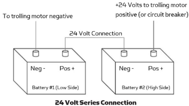
- The batteries must be wired in series, only as directed in wiring diagram, to provide 24 volts.
a. Connect a connector cable to the positive (+) terminal of battery 1 and to the negative (−) terminal of battery 2.
b. Connect positive (+) red lead to positive (+) terminal on battery 2.
c. Connect negative (−) black lead to negative (−) terminal of battery 1.
text_image
To trolling motor negative +24 Volts to trolling motor positive (or circuit breaker) 24 Volt Connection Neg - Pos + Battery #1 (Low Side) Neg - Pos + Battery #2 (High Side) 24 Volt Series Connection- For safety reasons do not switch the motor on until the propeller is in the water. If installing a leadwire plug, observe proper polarity and follow instructions in your boat owner's manual. See wiring diagram on following pages.
CAUTION
- For safety reasons, disconnect the motor from the battery or batteries when the motor is not in use or while the battery/batteries are being charged.
- Improper wiring of 24/36 volt systems could cause battery explosion!
- Keep leadwire wing nut connection tight and solid to battery terminals.
- Locate battery in a ventilated compartment.
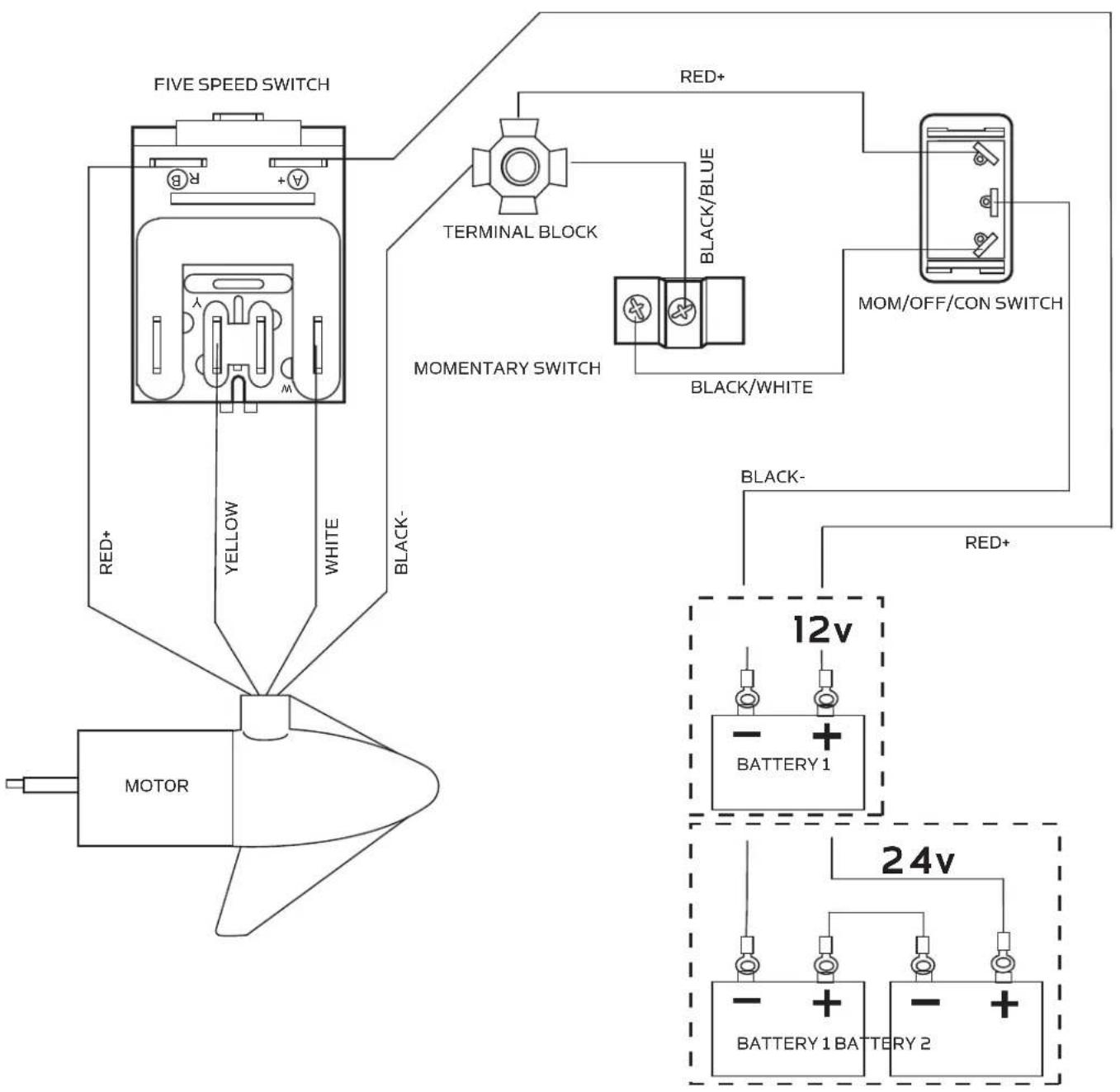
MOTOR WIRING DIAGRAM
NOTE: This is a universal, multi-voltage diagram. Double-check your motor's voltage for proper connections. Over-Current Protection Devices not shown in this illustration.
flowchart
graph TD
    A["MOTOR"] --> B["FIVE SPEED SWITCH"]
    B --> C["Terminal Block"]
    C --> D["MOMENTARY SWITCH"]
    D --> E["MOM/OFF/CON SWITCH"]
    E --> F["BATTERY 1"]
    E --> G["BATTERY 1 BATTERY 2"]
    B --> H["RED+"]
    B --> I["BLACK-/BLUE"]
    B --> J["YELLOW"]
    B --> K["WHITE"]
    B --> L["BACK-"]
    D --> M["12v"]
    M --> N["BATTERY 1"]
    M --> O["BATTERY 1 BATTERY 2"]
    M --> P["24v"]
    style A fill:#f9f,stroke:#333
    style B fill:#ccf,stroke:#333
    style C fill:#cfc,stroke:#333
    style D fill:#fcc,stroke:#333
    style E fill:#fcf,stroke:#333
    style F fill:#cff,stroke:#333
    style G fill:#ffc,stroke:#333
    style H fill:#fff,stroke:#333
    style I fill:#fff,stroke:#333
    style J fill:#fff,stroke:#333
    style K fill:#fff,stroke:#333
    style L fill:#fff,stroke:#333
USING AND ADJUSTING THE MOTOR
STOWING AND DEPLOYING THE MOTOR
WARNING:
When raising or lowering the motor, keep fingers clear of all hinge and pivot points and all moving parts.
MOUNT FEATURES
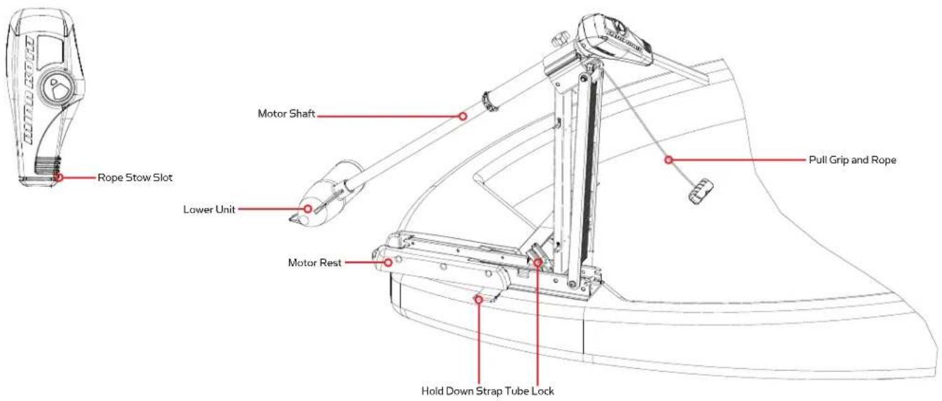
- The motor mount is designed to fold back and lock the motor flat on the deck when not in use and to provide secure stowage for transport.
- The pull grip and rope releases the lock bar, which automatically engages when the unit is lowered or raised into position. The pull grip and rope should be used to both lower and raise the unit.
- The motor rest positions the lower unit as it comes in contact with the nose of the mount and guides it onto the motor rest.
- The tube lock captures the motor shaft and keeps the lower unit centered on the motor rest.
- The hold-down strap must be used to place pressure on the motor shaft to hold the lower unit tightly against the motor rest when stowed.
- The pull grip and rope can be stored by placing the pull grip on top of the tube lock or into the rope stow slot on the control box of the motor.
TO DEPLOY THE MOTOR
Simply pull back and lift the motor off of the mount with the pull grip and rope. Lower the motor into the water using the pull grip and rope. The motor will lock into the deployed position automatically.
TO STOW THE MOTOR
Pull back and lift the motor out of the water with the pull grip and rope. Lower the lower unit onto the motor rest using the pull grip and rope. The motor will lock into the stowed position automatically. Wrap the hold-down strap over top of the motor shaft to secure the motor.
text_image
Rope Stow Slot Lower Unit Motor Rest Hold Down Strap Tube Lock Motor Shaft Pull Grip and RopeADJUSTING THE DEPTH OF THE MOTOR
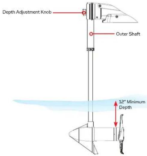
The propeller tip must be submerged at least 12" to avoid churning or agitation of surface water.
- With the motor deployed, firmly grasp the outer shaft or control head and hold it steady.
- Loosen the depth adjustment knob until the shaft slides freely.
- Raise or lower the motor to the desired depth.
- Turn the motor control head to the desired position.
- Tighten depth adjustment knob to secure the motor in place.
text_image
Depth Adjustment Knob Outer Shaft 12° Minimum DepthADJUSTING THE STEERING CABLE
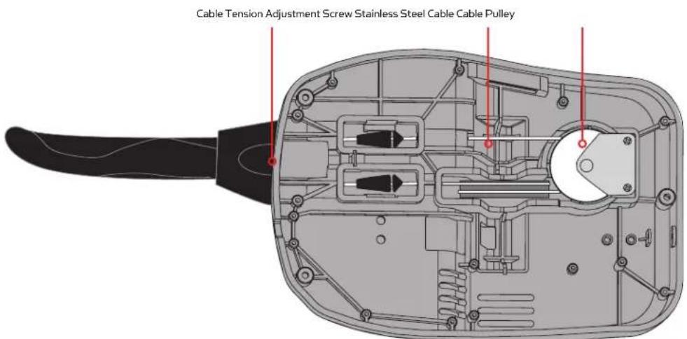
The steering cable tension is pre-set at the factory but will, through normal use, need occasional adjustment.
Adjust the tension of the cables by turning the cable tension adjustment screw (Phillips pan-head screw) located near the bottom of the foot pedal, just under the steering cable cover.
Turn the screw clockwise to increase tension and counter-clockwise to decrease tension.
text_image
Cable Tension Adjustment Screw Stainless Steel Cable Cable PulleyNOTE:
If the cable becomes too loose, it may disengage the wrap drum in the control box or the pulley in the foot pedal.
CONTROLLING SPEED & STEERING WITH THE FOOT PEDAL
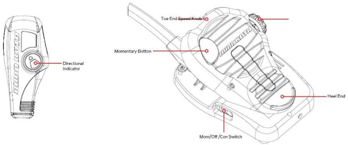
Most controls on the foot pedal are easy to operate by either foot or hand:
text_image
Directional Indicator Toe End Speed Knab Momentary Button Heel End Mom/Off /Con SwitchTO ADJUST MOTOR SPEED
Turn the speed knob clockwise to increase speed and counter-clockwise to decrease speed.
TO OPERATE THE MOTOR IN CONTINUOUS MODE
Press the Mom/Off /Con switch on the side of the pedal to the Con position.
TO OPERATE THE MOTOR IN MOMENTARY MODE
Press the Mom/Off/Con switch on the side of the pedal to the Mom position. A toe touch to the Momentary button on the foot pedal will now turn the motor on. Removing downward force on the Momentary button will turn the motor off.
TO TURN LEFT OR RIGHT
Push the toe end of the foot pedal down to turn right and push the heel end of the foot pedal down to turn left. The indicator on the motor head shows the direction of the motor. The motor will not maintain its own heading. You must keep your foot on the pedal to control steering during operation.
TO REVERSE THE MOTOR
The motor always travels in the direction of the indicator. You can reverse the direction of the motor by turning the motor 180° from straight ahead.
CAUTION:
- Switch the mom/off/con switch to "off" when not in use. If the motor control is left on and the propeller rotation is blocked, severe motor damage can result.
- Be sure to turn the motor off after each use.
- For safety reasons, disconnect the motor from the battery/batteries when the motor is not in use or while the battery/batteries are being charged.
SERVICE & MAINTENANCE
PROPELLER REPLACEMENT
TOOLS AND RESOURCES REQUIRED:
• 7/16" Box End Wrench
- Screwdriver (optional)
CAUTION:
Disconnect the motor from the battery before beginning any prop work or maintenance.
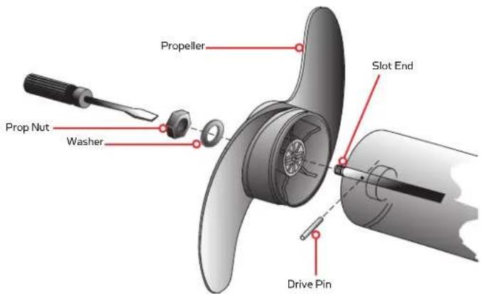
NOTE: The propeller on your motor may differ from the one pictured.
- Disconnect the motor from all sources of power prior to changing the propeller.
- Hold the propeller and loosen the prop nut with pliers or a wrench.
- Remove the prop nut and washer. If the drive pin is sheared or broken, you will need to hold the shaft stationary with a blade screwdriver pressed into the slot on the end of the shaft.
- Turn the old prop to horizontal (as illustrated) and pull it straight off. If drive pin falls out, push it back in.
- Align the new propeller with the drive pin.
- Install the prop washer and prop nut.
- Tighten the prop nut 1/4 turn past snug [25-35 inch lbs.] Do not over tighten as this can damage the prop.
GENERAL MAINTENANCE
- After use, the entire motor should be rinsed with freshwater, then wiped down with a cloth dampened with an aqueous based silicone spray. This series of motors is not equipped for saltwater exposure.
- The propeller must be inspected and cleaned from weeds and fi shing line after every use.
Fishing line and weeds can get behind the prop, damage the seals and allow water to enter the motor.
- Verify the prop nut is secure each time the motor is used.
- To prevent accidental damage during transportation or storage, disconnect the battery whenever the motor is off of the water. For prolonged storage, lightly coat all metal parts with an aqueous based silicone spray.
- For maximum battery life recharge the battery(s) as soon as possible after use. For maximum motor performance restore battery to full charge prior to use.
- Keep battery terminals clean with fine sandpaper or emery cloth.
- The propeller is designed to provide weed free operation with very high efficiency. To maintain this top performance, the leading edge of the blades must be kept smooth. If they are rough or nicked from use, restore to smooth by sanding with fine sandpaper.
text_image
Propeller Slot End Prop Nut Washer Drive PinTROUBLESHOOTING & REPAIR
-
Motor fails to run or lacks power:
-
Check battery connections for proper polarity.
- Make sure terminals are clean and corrosion free. Use fine sandpaper or emery cloth to clean terminals.
-
Check battery water level. Add water if needed.
-
Motor loses power after a short running time:
- Check battery charge. If low, restore to full charge.
- Motor is difficult to steer:
- Check steering cables for proper tension. Adjust as necessary.
- You experience prop vibration during normal operation:
- Remove and rotate the prop 180^ . See removal instructions in the Propeller Replacement Section.
- Experiencing interference with your fi shfi nder:
- You may, in some applications, experience interference in your depth finder display. We recommend that you use a separate deep cycle marine battery for your trolling motor and that you power the depth finder from the starting/cranking battery. If problems still persist, call our service department at 1-800-227-6433.
NOTE: For all other malfunctions, visit an authorized service center. You can search for an Authorized Service Center in your area by visiting our Authorized Service page, found online at minnkotamotors.com, or by calling our customer service number at 800-227-6433.
FOR FURTHER TROUBLESHOOTING AND REPAIR
We offer several options to help you troubleshoot and/or repair your product. Please read through the options listed below.

QUENTLY ASKED QUESTIONS
We have FAQs available on our website to help answer all of your Minn Kota questions. Visit minnkotamotors.com and click on "Frequently Asked Questions" to find an answer to your question.

L US (FOR U.S. AND CANADA)
Our consumer service representatives are available Monday – Friday between 7:00 a.m. – 4:30 p.m. CST at 800-227-6433. If you are calling to order parts, please have the 11-character serial number from your product, specific part numbers, and credit card information available. This will help expedite your call and allow us to provide you with the best consumer service possible. You can reference the parts list located in your manual to identify the specific part numbers.

AIL US
You can email our consumer service department with questions regarding your Minn Kota products. To email your question, visit minnkotamotors.com and click on "Support".

THORIZED SERVICE CENTERS
Minn Kota has over 300 authorized service centers in the United States and Canada where you can purchase parts or get your products repaired. Please visit our Authorized Service Center page on our website to locate a service center in your area.
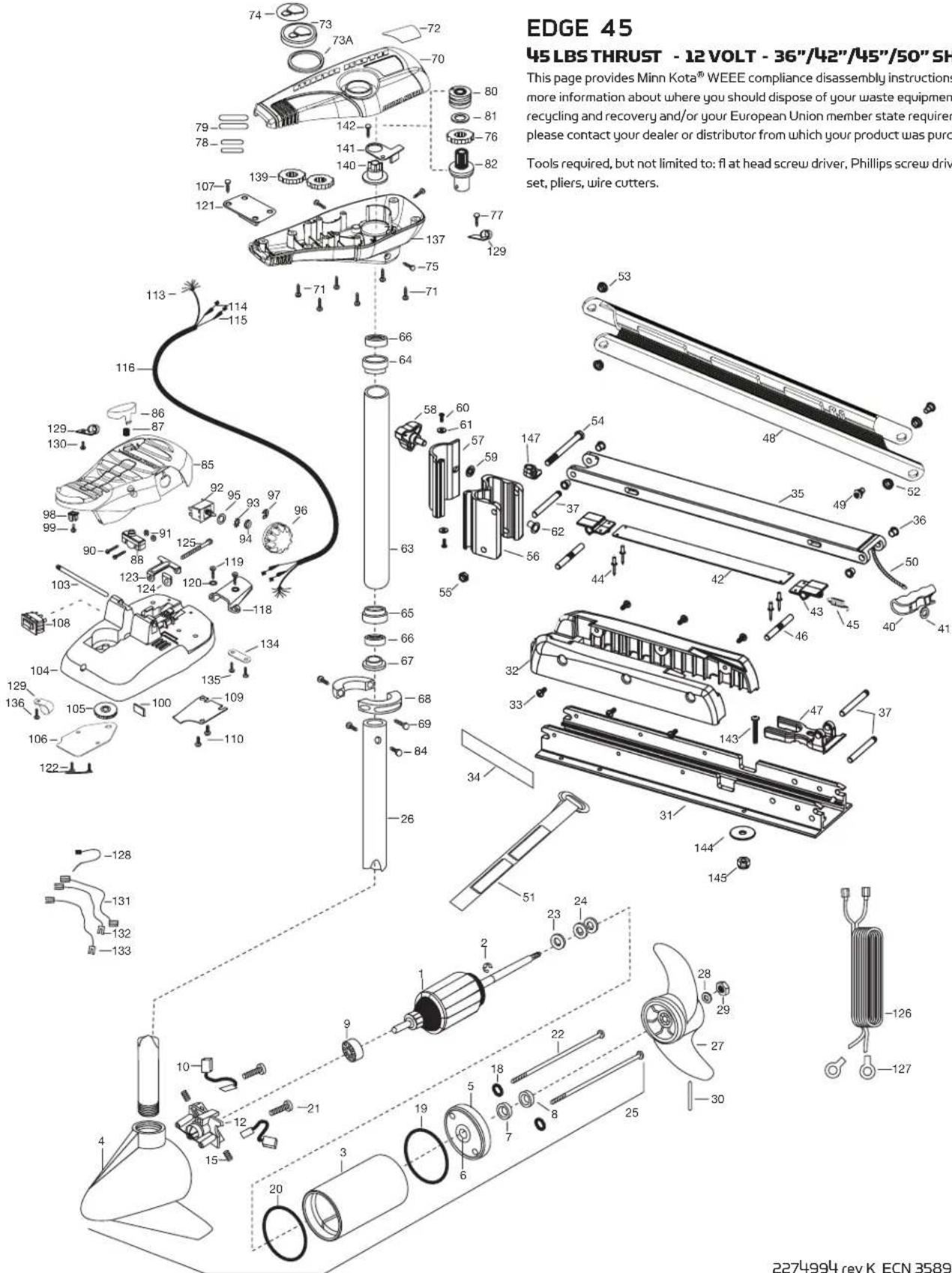
PARTS DIAGRAM
text_image
EDGE 45 45 LBS THRUST - 12 VOLT - 36"/42"/45"/50" SH This page provides Minn Kota® WEEE compliance disassembly instructions more information about where you should dispose of your waste equipment recycling and recovery and/or your European Union member state required please contact your dealer or distributor from which your product was purc. Tools required, but not limited to: flat head screw driver, Phillips screw drive set, pliers, wire cutters.This page provides Minn Kota® WEEE compliance disassembly instructions. For more information about where you should dispose of your waste equipment for recycling and recovery and/or your European Union member state requirements, please contact your dealer or distributor from which your product was purchased.
Tools required, but not limited to: flat head screw driver, Phillips screw driver, socket set, pliers, wire cutters.
2274994 rev K ECN 35896 8/14
EDGE 45
45 LBS THRUST - 12 VOLT - 36"/42"/45"/50" SHAFT
| ITEM | QTY | PART NUMBER | DESCRIPTION |
| 112 | 100-202 | ARM AS SEMB | LY 12 V 3.25 |
| 217 | 88-015 | RET AINING RING | |
| 312 | 200-079 | HOUSING AS SEMBLY CENTER 3.25 TXT | |
| 412 | 300-134 | HOUSING -AS SEMBLY BRUSH END 45"-50" | |
| 12-500-132 | BRUSH END HOUSING AS SEMBLY | ||
| 512 | 400-128 | PLA IN END HOUSING AS SEMBLY | |
| 611 | 4-049 | FLA NGE BEARING [SERVICE ONLY] | |
| 71 | 880-003 | SEAL | |
| 8 | 1 | 880-006 | SEAL WITH SHIELD |
| 911 | 40-010 | BALL BEARING | |
| 10 | 2 | 188-052 | BRUSH ASSEMBLY |
| 12 | 1738-030 | BRUSH PLA TE W/HOLDER 3.25 | |
| 15 | 2 | 975-032 | COMPRESSION SPRING |
| 18 | 2701-007 | O-RING | |
| 19 | 1 | 701-039 | O-RING MK406460 |
| 20 | 1701-041 | O-RING | |
| 21 | 2 | 830-001 | SCREW - SELF-THREAD #8-32X1.7 |
| 22 | 2 | 830-078 | THRU BOLT 8-32 X 8.96 |
| 23 | 1 | 990-067 | STEEL THRUST WASHER |
| 24 | 2 | 990-070 | NYLATRON WASHER |
| 25 | 1 | 2069286 | MTR ASSEMBLY 12V 3.25 |
| 1 | 2069285 | MTR ASSEMBLY 12V 3.25 | |
| 26 | 1 | 2032062 | TUBE (COMP) - 36" |
| 1 | 2032063 | TUBE (COMP) - 42" | |
| 1 | 2032061 | TUBE (COMP) - 45" | |
| 1 | 2032059 | TUBE (COMP) - 50" | |
| ■ | 1 | 1378121 | PROPELLER KIT |
| 27 | 12051122 | PROPELLER | |
| 28 | 12151726 | WAS HER-5/16 SS | |
| 29 | 1 | 2053101 | NUT-PROP NYLOC |
| 30 | 1 | 2092600 | DRIVE PIN |
| 31 | 1 | 2266507 | BOWPLATE, FW, LONG |
| 1 | 2266502 | BOWPLATE, FW, STD | |
| 32 | 1 | 2263905 | BLACK MOTOR REST |
| 33 | 6 | 2303430 | SCREW 1/4-20 X 5/8 |
| 34 | 2 | 2265667 | MOTOR REST DECAL, FW |
| ■ | 12991717 | MOUNT, AS SY LONG FW | |
| 12991716 | MOUNT, AS SY SHORT FW | ||
| 35 | 1 | 2264372 | LOWER ARM, FW, STD. |
| 36 | 4 | 2266002 | NYLINER 3/8" SHAFT |
| 37 | 3 | 2260503 | PIVOT PIN |
| 40 | 1 | 2150405 | PULL-GRIP |
| 41 | 12151700 | WAS HER-EYE SHAFT .562 OD | |
| ■ | 1 | 2993812 | LATCH STRAP ASSY, LONG |
| 1 | 2993811 | LATCH STRAP ASSY, STD | |
| 42 | 1 | 2263607 | LATCH STRAP, LONG |
| 1 | 2263605 | LATCH STRAP, STD | |
| 43 | 2 | 2261902 | LATCH BRACKET |
| 44 | 4 | 2268602 | RIVET 1/8" SS |
| 45 | 1 | 2262709 | SPRING-LATCH PIN |
| 46 | 2 | 2260501 | LATCH PIN |
| 47 | 1 | 2261544 | YOKE-TUBE |
| 48 | 1 | 2264272 | ARM-UPPER, LONG FW |
| 12264271 | ARM-UPPER, SHORT FW | ||
| 49 | 2 | 2263510 | BOLT-SHOULDER, SS |
| 50 | 1 | 2251601 | ROPE-44.5" |
| 12261603 | ROPE-48" | ||
| 51 | 1 | 2263805 | VELCRO STRAP |
| ITEM | QTY | PART NUMBER | DESCRIPTION |
| 52 | 1 | 2267302 | BUSHING —LOWER 7/16" ID, SS |
| 53 | 1 | 2267303 | BUSING — UPPER 3/8" ID, SS |
| 54 | 1 | 2263505 | BOLT 3/8-16 X 4.25" |
| 55 | 1 | 2263114 | NYLOCK JAM NUT 3/8-16 |
| 56 | 1 | 2261892 | HING BADE, FW |
| 57 | 1 | 2261897 | HINGE DOOR, FW |
| 58 | 1 | 2260905 | SOFT GRIP HANDLE, L&D |
| 59 | 1 | 2261728 | RETAINING WASHER- 3/8" |
| 60 | 2 | 2053415 | SCREW #8-32 X 3/8" TRI |
| 61 | 2 | 2261732 | WASHER #8, NYLON |
| 62 | 2 | 2264703 | THREADED INSERT |
| ■ | 1 | 2992015 | TUBE W/BEARING RACE AS SEMBLY 18" |
| 1 | 2992012 | TUBE W/BEARING RACE AS SEMBLY 21" | |
| 1 | 2992016 | TUBE W/BEARING RACE AS SEMBLY 24" | |
| 63 | 1 | 2272066 | 18" TUBE OUTER 4 HOLES |
| 1 | 2272069 | 21" TUBE OUTER 4 HOLES | |
| 1 | 2272067 | 24" TUBE OUTER 4 HOLES | |
| 64 | 1 | 2266260 | BEARING RACE |
| 65 | 1 | 2266220 | STEEL BEARING RACE |
| 66 | 2 | 2266000 | STEEL BEARING BALL |
| 67 | 1 | 2266115 | BEARING CONE |
| 68 | 2 | 2261622 | ALUMINUM HALF-COLLAR |
| 69 | 2 | 2263453 | SCREW — 1/4X20 X 1" |
| 70 | 1 | 2260215 | CONTROL BOX COVER |
| 71 | 6 | 2372100 | SCREW — 8-18 X 5/8 THD |
| 72 | 1 2275611 | DECA L-COVER, EDGE 45/FC | |
| 73 | 1 2260153 | POINTER DISC SHORT YELLOW | |
| 73A 1 | 2261733 | WAS HER-FOAM, INDICA TOR | |
| 74 | 1 | 2265800 | DECAL-INDICATOR |
| 75 | 3 | 2053414 | SCREW-8-32 X 1/2 TRI LOBE |
| 76 | 1 | 2267800 | GEAR-INDICATOR |
| 77 | 1 | 2372100 | SCREW-8-18 X 5/8 THD |
| 78 | 2 | 2375400 | SHRINK TUBE-1/4OD X 1-3/4 |
| 79 | 2 | 2355410 | SHRINK TUBE-3/8 OD X 2 |
| 80 | 1 | 2232360 | PULLEY — CABLE DRUM |
| 81 | 1 | 2261730 | NYLON A/T WASHER |
| 82 | 1 | 2996246 | BEARING RACE/ PINION AS SEMBLY |
| 84 | 2 | 2263410 | SCREW — #8-32 X 5/16 |
| 85 | 1 | 2994496 | FOOT PEDAL/PLUG AS SEMBLY |
| 86 | 1 | 2283700 | PUSH-BUTTON |
| 87 | 1 | 2302732 | LOWER PEDAL SPRING |
| 88 | 1 | 2264040 | MOMENTARY SWITCH |
| 90 2 | 2262114 | MOUNTING/SWITCH SCREW | |
| 91 | 2 | 2233100 | SWITCH MOUNT NUT |
| 92 | 1 | 2264026 | SWITCH — 5 SPEED |
| 93 | 1 | 2261701 | LOCKWASHER-STAR |
| 94 | 1 | 2263105 | HEX NUT |
| 95 | 1 2261715 | SPACER-SWITCH 5 SP MODELS | |
| 96 | 1 2230110 | SPEED CONTROL KNOB 5SPD | |
| 97 | 1 | 2263000 | E-RING TRU-ARC |
| 98 | 1 | 2260730 | CONNECTOR 1/4 MALE TAB |
| 99 | 1 | 2332103 | SCREW — #6-20 X 3/8 |
| ITEM | QTY | PART NUMBER | DESCRIPTION |
| 100 1 | 2266413 | TENSION SCREW PLA TE FOOT PEDAL | |
| 103 | 1 | 2260511 | PIN-PIVOT A/T FOOT PEDAL |
| 104 1 | 2992104 | FOOT PEDAL BAS E/PIN AS SEMBLY SONAR | |
| 105 | 1 | 2262301 | PULLEY-FOOT PEDAL |
| 106 | 1 | 2266401 | COVER-PULLEY STAMPING |
| 107 | 4 | 2223430 | SCREW- \#8 × 3/4 |
| 108 | 1 | 2254031 | MOM/OFF/COM SWITCH |
| 109 | 1 | 2266412 | FOOT PEDAL SWITCH PLATE |
| 110 | 2 | 2332103 | SCREW - \#6-20 × 3/8 THD |
| 113 1 | 2261208 | WIRE HARNES 5, A/T FOOT PEDAL | |
| 114 | 1 | 2267505 | RIGHT CABLE ASSEMBLY 5' |
| 115 | 1 | 2267515 | LEFT CABLE ASSEMBLY 5' |
| 116 | 1 | 2265430 | CABLE JACKET 5' |
| 118 | 1 | 2265115 | BOOT-FOOT PEDAL BASE |
| 119 | 2 | 2372100 | SCREW - \#8-18 × 5/8 THD |
| 120 | 2 | 2261714 | FOOT PEDAL WASHER |
| 121 1 | 2261901 | CONDUIT B | BRACKET |
| 122 | 2 | 2301310 | SCREW - \#8-18 × 3/4 " |
| 123 1 | 2263210 | CONDUIT ADJUST MENT BRACKET | |
| 124 | 1 | 2263140 | NYLOCK KEEPER |
| 125 | 1 | 2263466 | SCREW - 1/4-20 × 2 |
| 126 | 1 | 2261235 | LEADWIRE-BATTERY |
| 127 | 2 | 2020700 | TERMINAL RING, 3/8" |
| 128 | 1 | 2256300 | BLACK TIE WRAP-5.5" |
| 129 | 3 | 2263201 | CLA MP WIRE HARNES 5 MICRO |
| 130 | 1 | 2332103 | SCREW - \#6-20 × 3/8 THD |
| 131 1 | 2260301 | CONNECTING WIRE SWITCH | |
| 132 | 1 | 2260312 | WIRE - BLK W/SHT- 19 1/2" |
| 133 | 1 | 2260322 | WIRE - BLK W/BLUE -12" |
| 134 | 1 | 2263205 | LEADWIRE CLAMP |
| 135 | 2 | 9953104 | SCREW - \#8 × 1/2 " SS |
| 136 1 | 2301310 | SCREW - \#8-18 × 1/2 " SS | |
| 137 | 1 | 2262515 | CONTROL BOX BOTTOM |
| 139 | 2 | 2267800 | INDICATOR GEAR |
| 140 | 1 | 2262221 | YELLOW DRIVE INDICATOR |
| 141 | 1 | 2269105 | BRACKET/INDICATOR |
| 142 1 | 2223430 | SCREW - \#8 × 3/4 PPH TYPE 25 SS | |
| ■ | 1 | 2994838 | BAG ASSEMBLY |
| 143 | 6 | 2263462 | SCREW 1/4-20 × 2 SS |
| 144 | 6 | 2261713 | WASHER - 1/4 FLAT 18-18 |
| 145 | 6 | 2263103 | 1/4-20 NYLOCK-JAM NUT |
| 147 | 1 | 2262310 | GUIDE ROPE |
| ■ | 1 | 2883460 | SEAL & O-RING KIT |
THIS ITEM IS PART OF AN AS SEMBLY.
*THIS ITEM IS PART OF A KIT AND ONLY LISTED FOR VIEWING PURPOSES.
COMPLIANCE STATEMENTS
ENVIRONMENTAL COMPLIANCE STATEMENT:
It is the intention of JOME to be a responsible corporate citizen, operating in compliance with known and applicable environmental regulations, and a good neighbor in the communities where we make or sell our products.
WEEE DIRECTIVE:
EU Directive 2002/96/EC “Waste of Electrical and Electronic Equipment Directive (WEEE)” impacts most distributors, sellers, and manufacturers of consumer electronics in the European Union. The WEEE Directive requires the producer of consumer electronics to take responsibility for the management of waste from their products to achieve environmentally responsible disposal during the product life cycle.
WEEE compliance may not be required in your location for electrical & electronic equipment (EEE), nor may it be required
for EEE designed and intended as fixed or temporary installation in transportation vehicles such as automobiles, aircraft, and boats. In some European Union member states, these vehicles are considered outside of the scope of the Directive, and EEE for those applications can be considered excluded from the WEEE Directive requirement.
natural_image
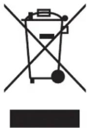
Simple line drawing of a trash bin with crossed lines indicating no waste or discharge (no text or symbols)This symbol (WEEE wheelie bin) on product indicates the product must not be disposed of with other household refuse. It must be disposed of and collected for recycling and recovery of waste EEE. Johnson Outdoors Inc. will mark all EEE products in accordance with the WEEE Directive. It is our goal to comply in the collection, treatment, recovery, and environmentally sound disposal of those products; however, these requirement do vary within European Union member states. For more information about where you should dispose of your waste equipment for recycling and recovery and/or your European Union member state requirements, please contact your dealer or distributor from which your product was purchased.
DISPOSAL:
Minn Kota motors are not subject to the disposal regulations EAG-VO (electric devices directive) that implements the WEEE directive. Nevertheless never dispose of your Minn Kota motor in a garbage bin but at the proper place of collection of your local town council.
Never dispose of battery in a garbage bin. Comply with the disposal directions of the manufacturer or his representative and dispose of them at the proper place of collection of your local town council.
WARNING: This product contains chemicals known to the State of California to cause cancer and birth defects or other reproductive harm.
NOTES
RECOMMENDED ACCESSORIES
ON-BOARD & PORTABLE BATTERY CHARGERS
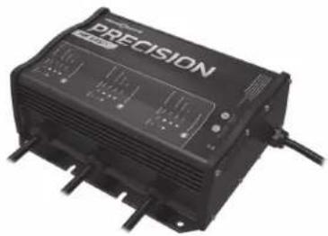
Stop buying new batteries and start taking care of the ones you've got. Many chargers can actually damage your battery over time – creating shorter run times and shorter overall life. Digitally controlled Minn Kota chargers are designed to provide the fastest charge that protect and extend battery life.
natural_image
Black precision electronic device with ventilation grilles and buttons (no visible text or symbols)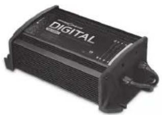
natural_image
Black digital audio device with no visible text or symbols on body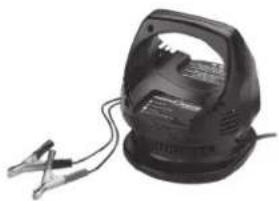
natural_image
Black industrial electrical lamp with clamps and a handle (no visible text or symbols)MK212DMK345PC MK105P
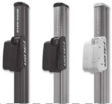
TALON SHALLOW WATER ANCHOR
Talon deploys faster, holds stronger and runs quieter than any other shallow water anchor. Available in depths up to 12' and bold color options, it boasts an arsenal of features and innovations that no other anchor can touch:
natural_image
Three vertical metal bars with black and white labels, no visible text or symbols on the bars themselves.• Vertical, multi-stage deployment
- User-Selectable Anchoring Modes
- 2x Anchoring Force
- Fast Deploy
- Auto Up/Down
- Triple Debris shields*
• Built-In Wave Absorption - Noise Dissipation
- Versatile Adjustments
*available on 10' and 12' models only
MINN KOTA ACCESSORIES
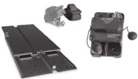
We offer a wide variety of trolling motor accessories, including:
natural_image
Exterior view of a battery pack and its internal components (no visible text or symbols)- 60-Amp Circuit Breaker
- Mounting Brackets
- Stabilizer Kits
-
Extension Handles
-
Battery Connectors
- Battery Boxes
- Quick Connect Plugs
For a complete listing of Minn Kota accessories, visit minnkotamotors.com
Follow us:


minnkotamotors.com
Minn Kota Consumer & Technical Service
Johnson Outdoors Marine Electronics, Inc.
PO Box 8129
Mankato, MN 56001
121 Power Drive
Mankato, MN 56001
Phone (800) 227-6433
Fax (800) 527-4464

©2014 Johnson Outdoors Marine Electronics, Inc.
All rights reserved.
minn.kota
natural_image
Technical line drawing of a mechanical device with attached cable and base mount (no text or symbols)EDGE
MOTEUR DE PÊCHE À LA TRAÎNE MONTÉ SUR L'ÉTRAVE
MANUEL DE L'UTILISATEUR
MANUEL CE D'UN MASTER (CE/C-TICK CERTIFIED MODELS)
EXCLUSIONS & LIMITATIONS
INFORMATION SUR LE SERVICE MINN KOTA
natural_image
Technical line drawing of a mechanical device with a central vertical axis and curved base (no text or symbols)natural_image
Technical line drawing of a mechanical assembly with no visible text or symbolsDÉCLARATION DE CONFORMITÉ
DÉCLARATION DE CONFORMITÉ ENVIRONNEMENTALE
natural_image
Symbol of a trash bin crossed with two crossed lines and a solid rectangle below (no text or labels)natural_image
Black precision electronic device with control panel and wiring (no visible text or symbols)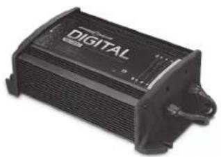
natural_image
Black digital audio device with no visible text or symbols on body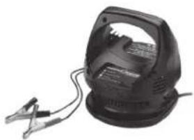
natural_image
Black industrial electrical lamp with attached clamp (no visible text or symbols)MK212DMK345PC MK105P
natural_image
Three vertical metal bars with black and white connectors, arranged side by side (no visible text or symbols)ACCESSOIRES MINN KOTA
natural_image
Electronic components including a battery pack, switch, and a NE-AM9 device with earphones (no visible text or symbols)Minn Kota Consumer & Technical Service Johnson Outdoors Marine Electronics, Inc. PO Box 8129 Mankato, MN 56001
121 Power Drive Mankato, MN 56001 Phone (800) 227-6433 Fax (800) 527-4464