Villarrica - Fireplace Klarstein - Free user manual and instructions
Find the device manual for free Villarrica Klarstein in PDF.

User questions about Villarrica Klarstein
0 question about this device. Answer the ones you know or ask your own.
Ask a new question about this device
Download the instructions for your Fireplace in PDF format for free! Find your manual Villarrica - Klarstein and take your electronic device back in hand. On this page are published all the documents necessary for the use of your device. Villarrica by Klarstein.
USER MANUAL Villarrica Klarstein
SAINT HELENS STUDIO LOFT 2
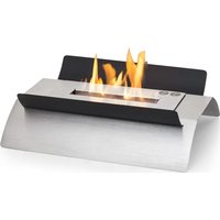
Elektrischer Kamin Fireplace Heater Cheminée électrique Camino elettrico Chimenea eléctrica
10038007 10038615 10038616 10038617 10038618

COMFORTING OMFORTING FORTINGCON TINGCOMFO COMFORTING OMFORTING FORTINGCON TINGCOMFO
KLARSTEIN
www.klarstein.com
Note: This product is only suitable for well insulated spaces or occasional use.
text_image
QR code image containing encoded data, no visible human-readable textINHALTSVERZEICHNIS
Produktdatenblatt 4
text_image
Technical diagram of a microwave oven with labeled components and internal structureTeileliste
text_image
Technical diagram of a multi-level appliance assembly with numbered components for identification and assembly reference.Teileliste
text_image
Technical diagram showing assembly steps of a mechanical component with labeled parts and numbered callouts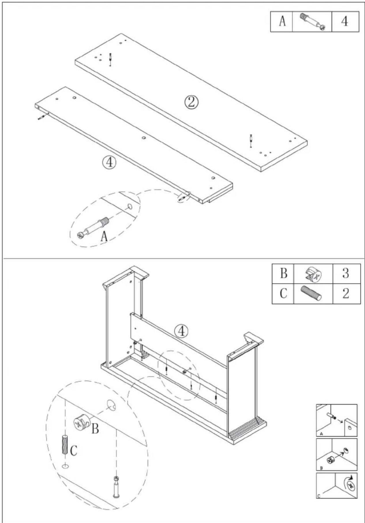
text_image
Technical diagram showing assembly steps of a mechanical component with labeled parts and corresponding exploded views.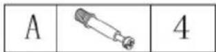

text_image
Technical diagram of a mechanical assembly with labeled components and motion indicators| B | 3 | |
| C | 2 |

text_image
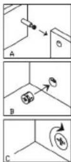
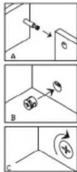
Diagram showing three labeled steps (A, B, C) of a mechanical or electrical component with directional arrows and circular symbols.
text_image
Technical diagram of a mechanical assembly with labeled components and numbered parts| B | 2 | |
| C | 2 |

text_image
Diagram showing three steps (A, B, C) of a mechanical or electrical component with directional arrows and circular symbols indicating motion.
text_image
Technical diagram of a mechanical assembly with labeled parts and a magnified inset showing a screw and nut assembly.| D | 6 |
text_image
B 2 C 6 D 4 ② L C C B D C| E | 6 |
text_image
Technical diagram of a microwave oven assembly with numbered components and exploded viewTeileliste
text_image
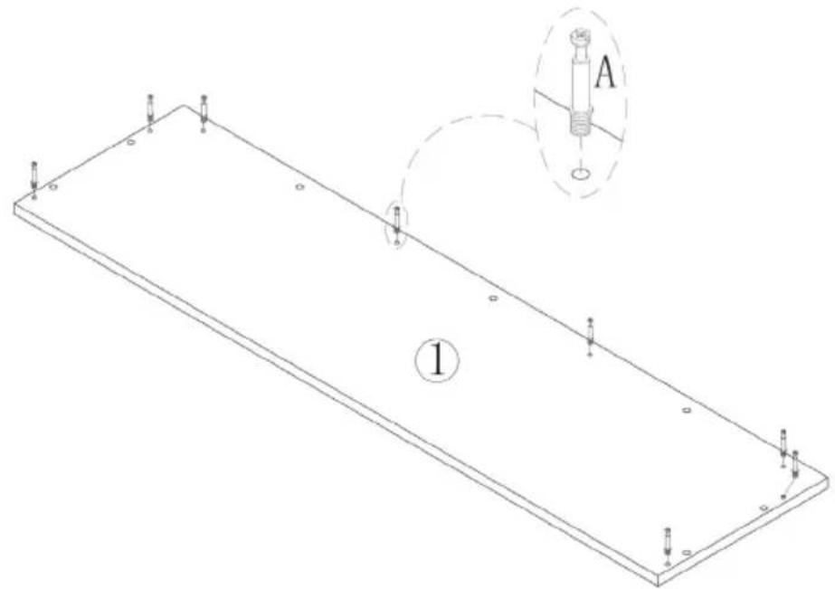
Technical diagram of a rectangular plate with labeled components and an inset showing a mechanical component labeled A.STEP 2
| B | 6 | |
| C | 4 |

text_image
Technical diagram of a mechanical assembly with numbered components and exploded view, including labeled parts A, B, C and numbered parts 2, 5.STEP 3
| A | 8 |

text_image
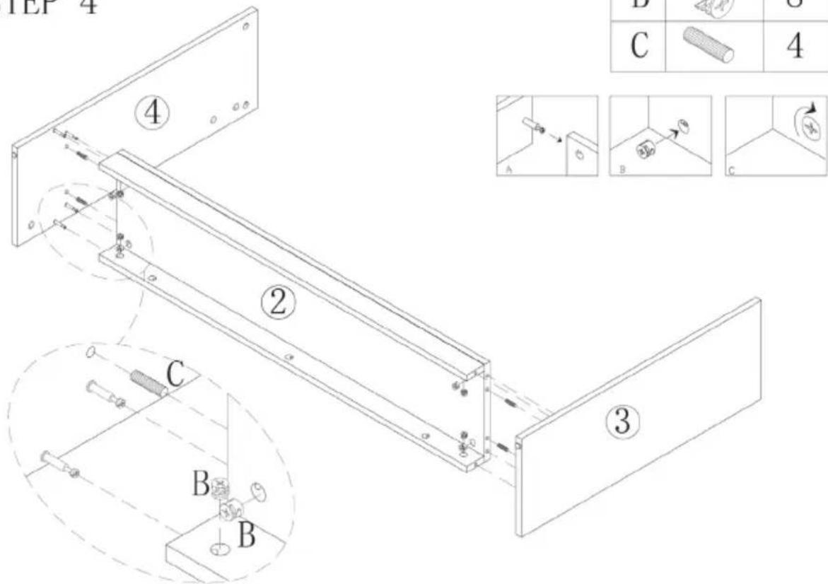
A ④ ③STEP 4
| B | 8 | |
| C | 4 |

text_image
1E1-4 ④ ② ③ B C 4 A B C
text_image
Technical diagram showing three labeled mechanical or structural components (A, B, C) with arrows indicating direction and a circular symbol labeled 'AB'.STEP 5
| A | 10 |

text_image
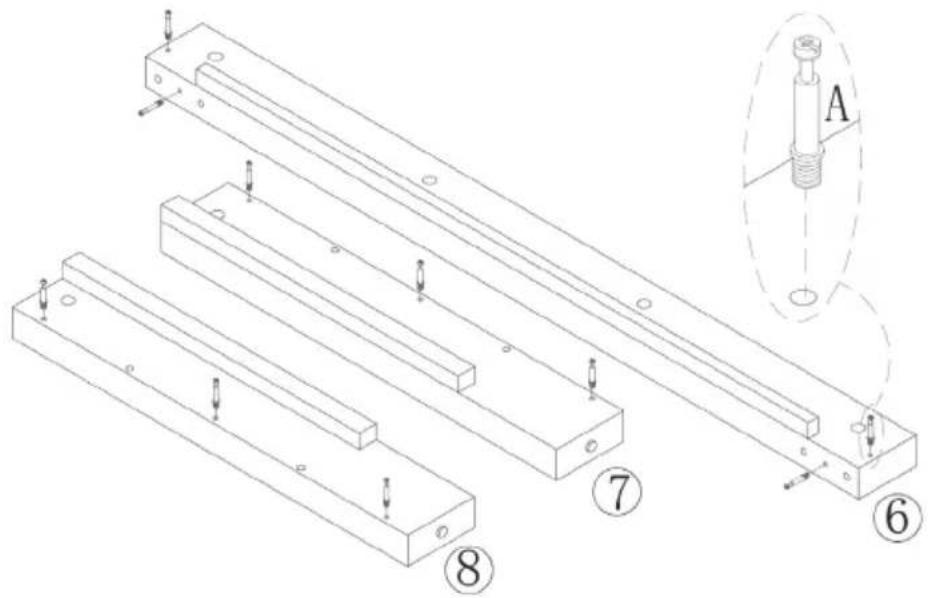
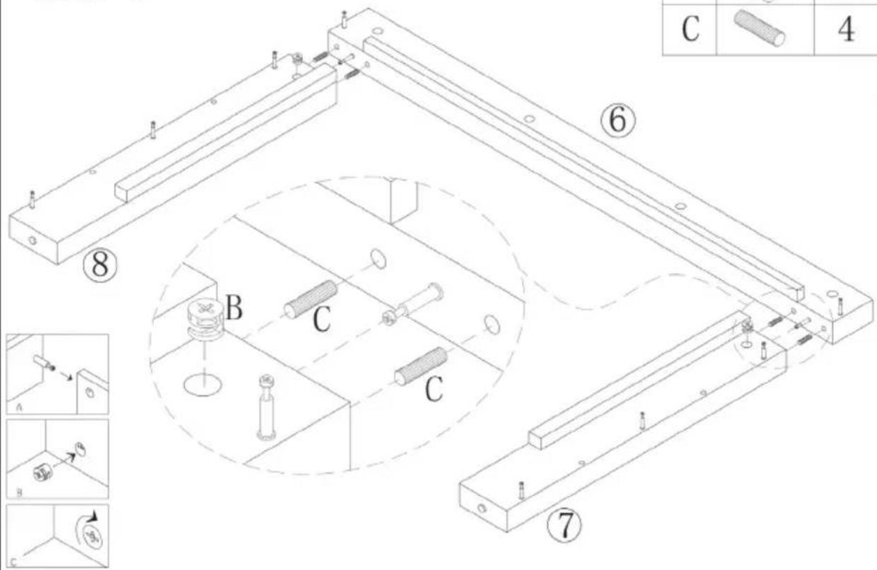
Technical diagram showing assembly of two parallel metal beams with labeled components and a magnified inset view labeled A.STEP 6
| B | 2 | |
| C | 4 |

text_image
Technical diagram of a mechanical assembly with labeled parts and exploded views, including numbered annotations and component callouts.STEP 7
| B | 8 | |
| C | 4 |

text_image
Technical diagram of a mechanical assembly with numbered components and labeled parts (A, B, C, D, E, F)STEP 8
| A | 8 |

natural_image
Isometric line drawing of a rectangular plate with mounting holes and a small inset showing a mechanical component labeled A (no text or symbols present)STEP 9
| B | 8 | |
| C | 7 |

text_image
Technical diagram of a cabinet or enclosure with labeled components and assembly steps, including section B and detailed views A, B, C.STEP 10
| D | 6 |
Member of Berlin Brands Group
Handwerkerstr. 11
15366 Dahlwitz-Hoppegarten
Deutschland
natural_image
Symbol of a trash bin crossed with a diagonal line, representing no waste or discharge (no text or labels)Berlin Brands Group UK Ltd
PO Box 1145
Oxford, OX1 9UW
United Kingdom
Dear customer,
Congratulations on the purchase of your device. Please read the following instructions carefully and follow them to prevent potential damage. We accept no liability for damage caused by disregarding the instructions and improper use. Please scan the QR code to access the latest operating instructions and further information about the product.

text_image
QR code image containing encoded data, no visible human-readable textCONTENTS
Product data sheet 38
Safety Instructions 39
Device overview 40
Display indications 41
Setup and operation 42
Individual parts overview (10038007) 46
Assembly (10038007) 47
Individual parts overview (10038615 & 10038616) 48
Before assembly (10038615 & 10038616) 50
Assembly (10038615 & 10038616) 51
Individual parts overview (10038617 & 10038618) 56
Before assembly (10038617 & 10038618) 58
Assembly (10038617 & 10038618) 59
Troubleshooting 65
Disposal considerations 68
Manufacturer & importer (UK) 68
TECHNICAL DATA
| Article number | 10038007, 10038615, 10038616, 10038617, 10038618 |
| Power supply 220-240 V ~ 50 Hz | |
| Power 1700 - 1900 W |
PRODUCT DATA SHEET
| Model identifier(s) | 10038007, 10038615, 10038616, 10038617, 10038618 | |||||
| Specification Symbol Value Unit | Specification Unit | |||||
| Heat output Only for electric storage room heaters: Type of heat supply control | ||||||
| Nominal heat output P | nom | 1.902 kW | W Manual control of the heat supply with integrated thermostat | N/A | ||
| Minimum heat output (guide value) | Pmin | 1.778 kW | W Manual control of the heat supply with feedback of the room and/or outside temperature | N/A | ||
| Maximum continuous heat output | Pmax,c | 1.902 kW | W Electronic control of the heat supply with feedback of the room and/or outside temperature | N/A | ||
| Auxiliary power consumption | Heat output with fan support N/A | |||||
| Nominal heat output el | max | N/A kW | Type of heat output/room temperature control | |||
| With minimum heat output | elmin | N/A kW | Single stage | heat output, no room temperature control | no | |
| Standby mode | elSB | 0.37 | W | Two or more manually adjustable levels, no room temperature control | no | |
| Room temperature control with mechanical thermostat | no | |||||
| With electronic room temperature control | no | |||||
| With electronic room temperature control and time of day control | no | |||||
| With electronic room temperature control and day of week control | yes | |||||
| Other regulatory options | ||||||
| Room temperature control with presence detection | no | |||||
| Room temperature control with open window detection | yes | |||||
| With remote control option | no | |||||
| With adaptive control of the heating start | no | |||||
| With operating time limit | no | |||||
| With black ball sensor | no | |||||
| Contact details | Chal-Tec GmbH, Wallstraße 16, 10179 Berlin, Germany. | |||||
SAFETYINSTRUCTIONS
- Before use, check the voltage information on the rating plate and only connect the device to sockets that correspond to the nominal voltage of the device.
- If the power cord is damaged, have it replaced by a trained professional.
- Do not place the fi replace directly under the mains socket.
- Keep a distance of one metre from combustible materials such as furniture, curtains or similar.
- Use the device out of the reach of children. Children may only operate the device under supervision.
- The device is intended for use in the home and similar environments only. It is not intended for commercial use.
- Do not use the device if it malfunctions or has been damaged in any way.
• Repairs may only be carried out by trained specialists. - Incorrectly or independently performed repairs pose a risk of injury.
- Do not run the power cord under carpets or rugs.
- Make sure that the power cord does not come into contact with sharp edges or hot surfaces.
• To prevent overheating, do not cover the fi replace. - Do not use the device with an external timer, a remote controlled socket or any other device that automatically turns the fi replace on and off.
- Do not immerse the device in water or other liquids.
- Do not use the device near bathtubs, showers or swimming pools.
- Do not use the device outdoors.
- Do not use the device with wet hands.
- Do not use the device on or near hot surfaces
- Do not use the device with a damaged power cord.
- Before cleaning, unplug the device from the wall outlet and allow it to cool completely.
- Do not use abrasive cleaners for cleaning.
- Only use accessories that are expressly approved for this purpose by the manufacturer.
- Children from the age of 8 years and mentally, sensory and physically impaired persons may only use the device if they have been informed in detail about the functions and safety precautions by a supervisor responsible for them beforehand and understand the associated risks.
• Make sure that children do not play with the device.
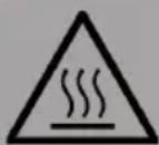
CAUTION
Risk of burns! Some parts of the device can become very hot. Be careful not to burn yourself or your children with it.
DEVICE OVERVIEW
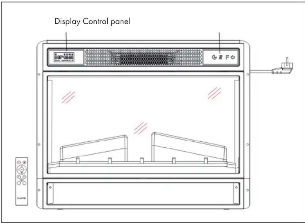
Front view
text_image
Display Control panelNote:
- The unit can be used with the remote control included with delivery as well as with the control panel, which is located on the upper right side of the unit.
- The unit has a mains switch that regulates the power supply. The power switch must be in the "On" position for the unit to be used.
- When you switch on the unit for the first time, the time must be set immediately. Otherwise, the time will only be displayed as "00:00" and the weekly timer will not be available.
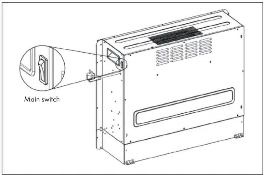
Rear view
text_image
Main switchDISPLAY INDICATIONS
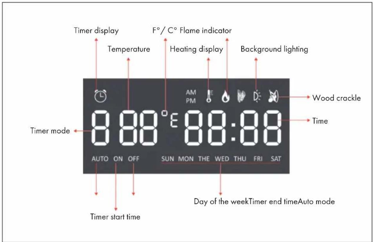
text_image
Timer display Temperature F° / C° Flame indicator Heating display Background lighting Timer mode 8 88° E 88:88 AUTO ON OFF SUN MON THE WED THU FRI SAT Timer start time Wood crackle Time Day of the weekTimer end timeAuto modeNote: When you switch on the fireplace, the time lights up. After 60 seconds, the fireplace switches off automatically. You can switch it on again with any button. The backlight and the "wood crackle" function are not available on this model.
SETUP AND OPERATION
Manual operation
| Timer Heating function Flame On/off | |
| Press this button to switch the unit on/off or press and hold this button for 10 seconds to activate/deactivate the child lock. As soon as the child lock has been activated, the heating function is switched off but the flame remains on. | |
| F | Press this key repeatedly to select "L1", "L2", "L3", "L4" or "OFF" (4 brightness levels that can be selected). |
| Press this key several times to set the following functions: Room temperature between 17 °C and 27 °C (62 °F - 82 °F) > Heating continuously ON > Heating OFF. After setting, the temperature you have set flashes 5 times on the screen and is then saved. To switch between Fahrenheit and Celsius, press and hold the button for 5 seconds. | |
| Press this button several times to adjust the operating time of the device. You can set the operating time to 1 > 2 > 3 > 4 > 5 > 6 > 7 > 8 > 9 > OFF >1 (...). It is not possible to operate the weekly timer manually. If the weekly timer has been activated, the normal timer is not available. | |
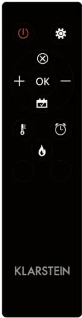
Using the remote control
Before using the remote control, make sure that the mains plug of the unit is plugged in and that the mains switch is in the "ON" position.
Note: When using the remote control, make sure that you point the remote control at the screen of the unit when pressing any of the buttons. A beep will sound. There may be a slight delay in the signal transmission from the transmitter to the receiver. Do not press the respective button more than once within 2 seconds during operation.
| Function Description | ||
| On/off switch |  | Press this button to switch the device on or off. Press this button once to turn the device and the flame effects on. If you press this button again, the unit and the flame effects are switched off and the unit is in standby mode. |
| To activate the child lock, press and hold the button for 10 seconds. As soon as the child lock is active, the heating goes off but the flame effect remains on. | ||
| Flame Four brightness le |  | be selected (L1-L4). |
| Timer | Press the timer button to select one of the following timer settings: 1 >2 >3 >4 >5 >6 >7 >8 >9 >OFF >1 | |
| Heating function |  | Press this key several times to set the following functions: Room temperature between 17 °C and 27 °C (62 °F - 82 °F) > Heating continuously ON > Heating OFF. |
| To activate the child lock, press and hold the button for 10 seconds. As soon as the child lock is active, the heating goes off but the flame effect remains on. | ||
| To switch between Fahrenheit and Celsius, press and hold the button for 5 seconds. |
text_image
KLARSTEIN| Function Description | ||
| Setting |  | When the unit is on or in standby, press and hold the settings icon on the remote control for 3 seconds or press and hold the timer button on the control panel for 3 seconds in standby. The display flashes [00:00]. First set the current time. Press the [+] button on the remote control to set the hour and the [-] button to set the minute. |
| Weekly timer After settir |  | Current time, press the settings icon again to activate the weekly timer, then press the calendar icon to select Sunday to Saturday. The selected date lights up. Then press the settings icon to set the switch-off time and switch-on time in succession, and then press the OK button directly to complete the weekly timer settings. |
| Note: The current time must be set after switching on or off for the first time, otherwise the clock remains in the "00:00" state and the timer function cannot be used | ||
| The clock lights up automatically when the power supply is switched on. The clock automatically switches off the display after 60 seconds in standby mode. Press any function key to then display the clock again. | ||
| If you are not in settings mode, press the calendar icon directly to select the weekly timer setting. |
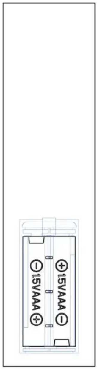
text_image
15VAAA +15VAAA -15VAAA- Old and new batteries must not be mixed.
- Only use standard AAA batteries. Make sure that children do not swallow the batteries.
• Non-rechargeable batteries must not be recharged. - Insert the batteries with correct polarity (see illustration).
- Remove dead batteries from the remote control immediately.
• Always buy the right size and type of batteries that are best suited for the intended use. - Replace all batteries of a set at the same time.
- Clean the battery contacts and also those of the unit before inserting the battery.
- Dispose of used batteries immediately as indicated in the chapter "Disposal".
INDIVIDUAL PARTS OVERVIEW (10038007)
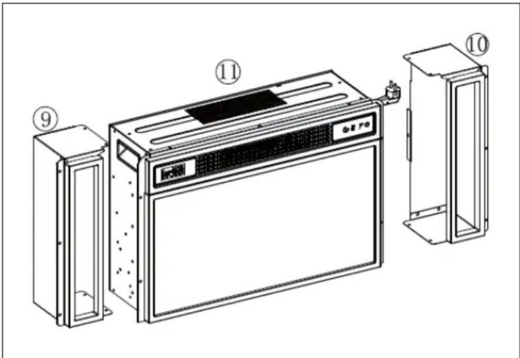
text_image
Technical diagram of a microwave oven with labeled components and internal compartmentsParts list
| No. | Description Pc. | |
| 9 | Left box 1 | |
| 10 | Right box 1 | |
| 11 | Electric fireplace 1 |
Small parts
| No. | Description Pc. | ||
| A | Screw (M4x8) 10 | ||
ASSEMBLY (10038007)
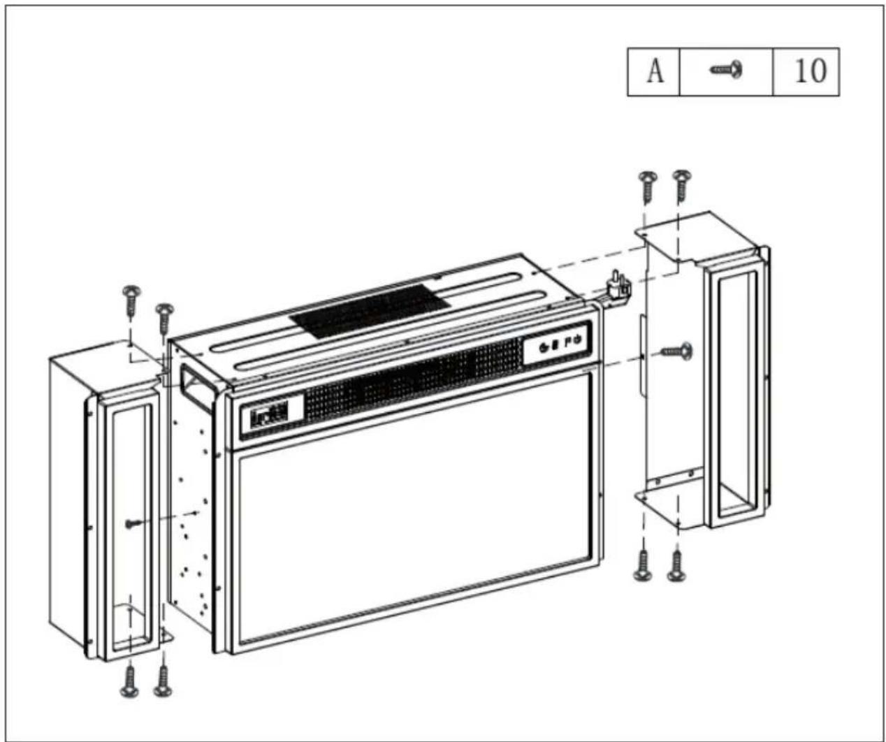
text_image
A 10INDIVIDUAL PARTS OVERVIEW (10038615 & 10038616)
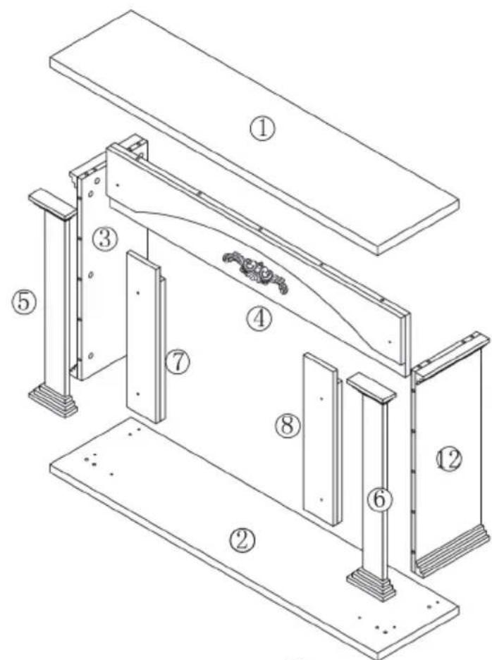
text_image
Technical diagram of a mechanical assembly with numbered components for identification
text_image
Technical diagram of a refrigerator with numbered parts and labeled componentsParts list
| No. | Description Pc. | |
| 1 | Upper plate 1 | |
| 2 | Lower plate 1 | |
| 3 | Left side plate 1 | |
| 4 | Front plate 1 | |
| 5 | Left front plate 1 | |
| 6 | Right front panel 1 | |
| 7 | Left panel 1 | |
| 8 | Right panel 1 | |
| 9 | Left box 1 | |
| 10 | Right box 1 | |
| 11 | Electric fireplace 1 | |
| 12 | Right side panel 1 |
Small parts
| No. | Description Pc. | ||
| A | 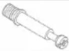 | Metal stud | 17+1 |
| B |  | Metal stud | 17+1 |
| C | 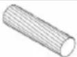 | Dowel | 18+1 |
| D |  | Long screw | 10+1 |
| E |  | Screw | 16+1 |
BEFORE ASSEMBLY (10038615 & 10038616)
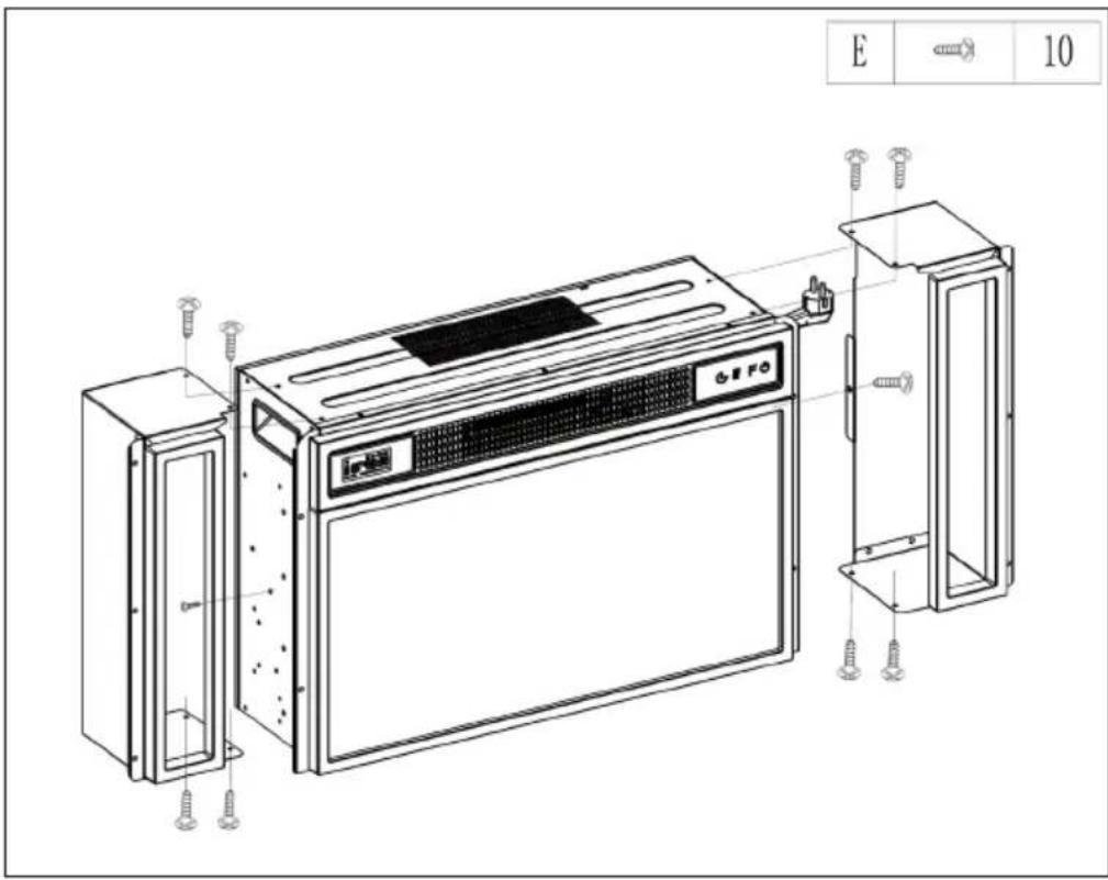
text_image
E 10ASSEMBLY (10038615 & 10038616)
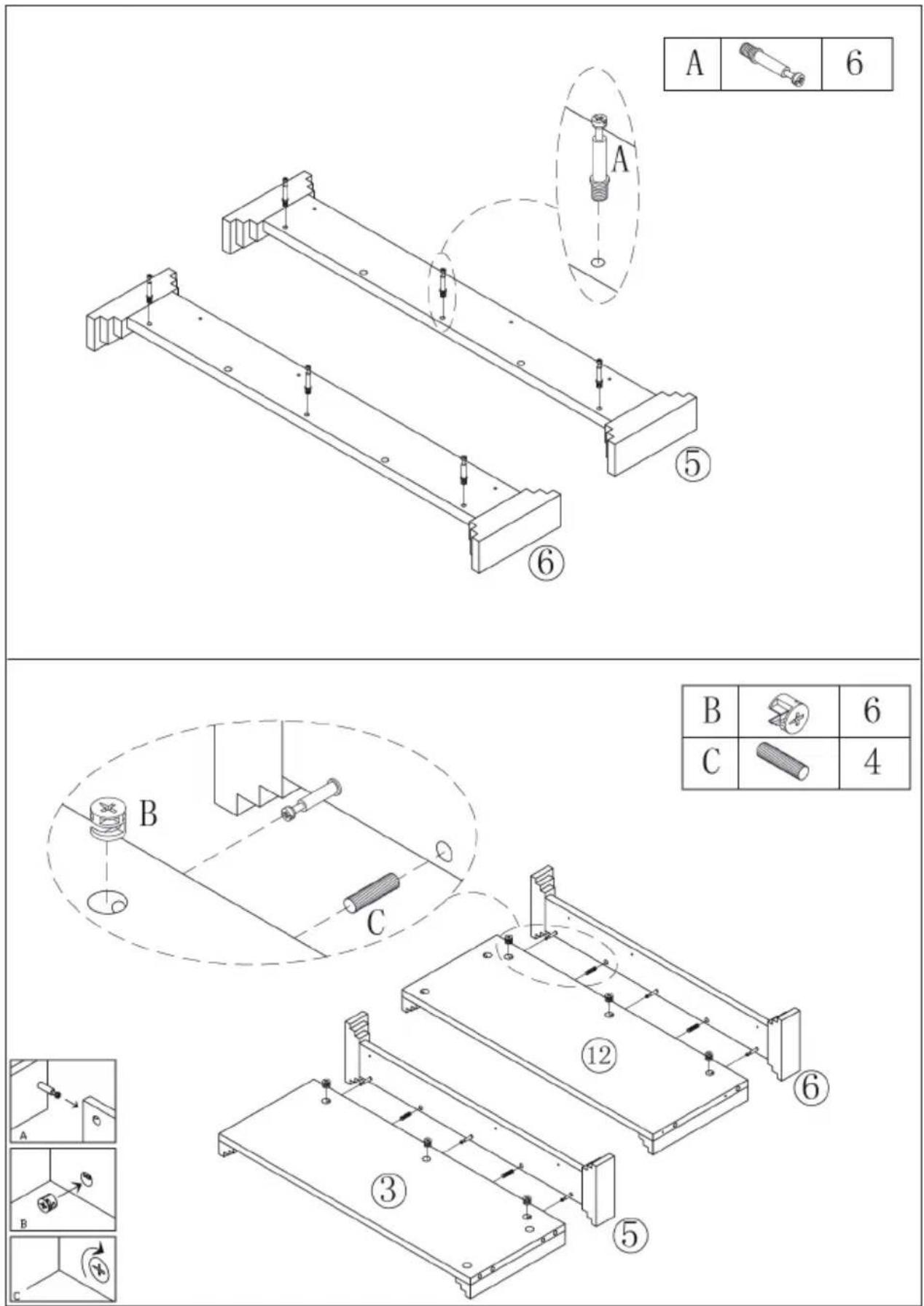
text_image
A 6 ⑤ ⑥ B 6 C 4 ⑫ ⑬ ③ ⑤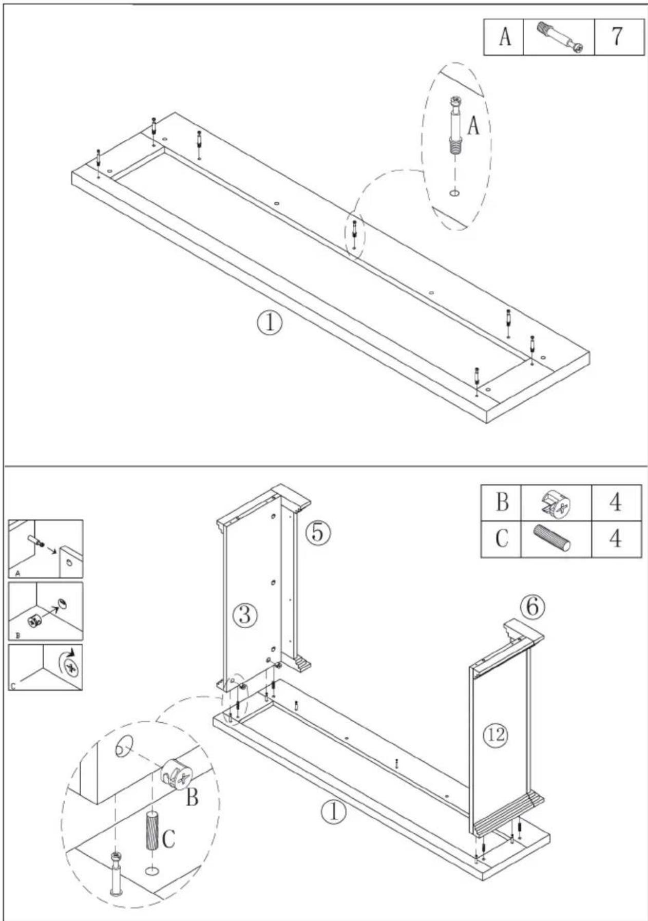
text_image
Technical diagram showing assembly steps of a mechanical component with labeled parts and numbered callouts
text_image
Technical diagram showing assembly steps of a mechanical component with labeled parts and corresponding exploded views.| A | 4 |
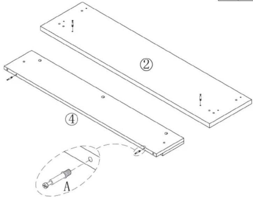
text_image
Technical diagram showing two rectangular panels labeled ② and ④ with a magnified inset of a mechanical component labeled A.| B | 3 | |
| C | 2 |
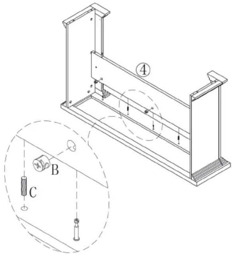
text_image
Technical diagram of a mechanical assembly with labeled components and motion indicators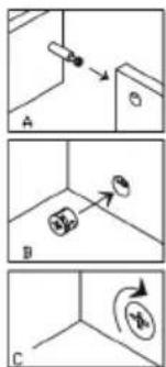
text_image
Diagram showing three labeled steps (A, B, C) of a mechanical or electrical component with directional arrows and circular symbols.
text_image
Technical diagram of a mechanical assembly with labeled components and numbered parts| B | 2 | |
| C | 2 |
text_image
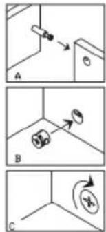
Diagram showing three steps (A, B, C) of a mechanical or electrical component with directional arrows and circular features.
text_image
Technical diagram of a mechanical assembly with labeled parts and a magnified inset showing a screw and nut assembly.| D | 6 |

text_image
B 2 C 6 D 4 ② L C C B D C| E | 6 |
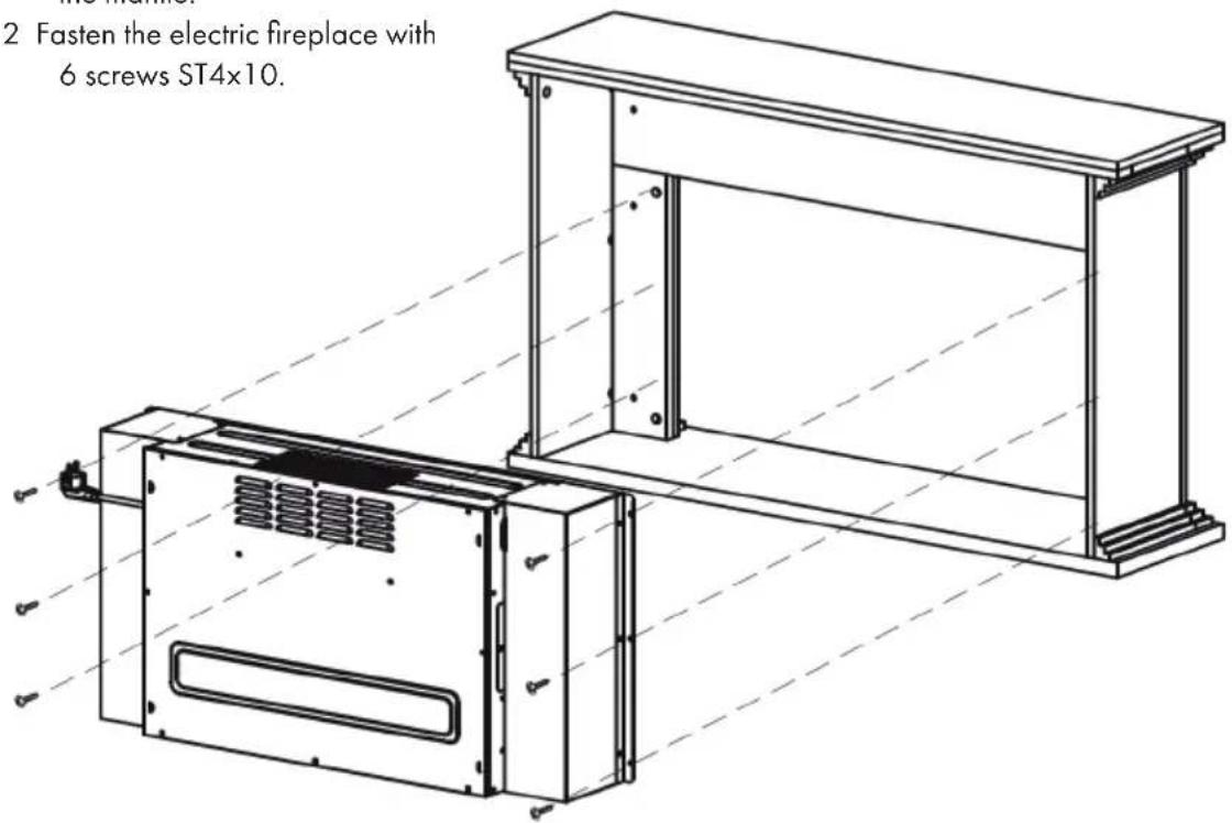
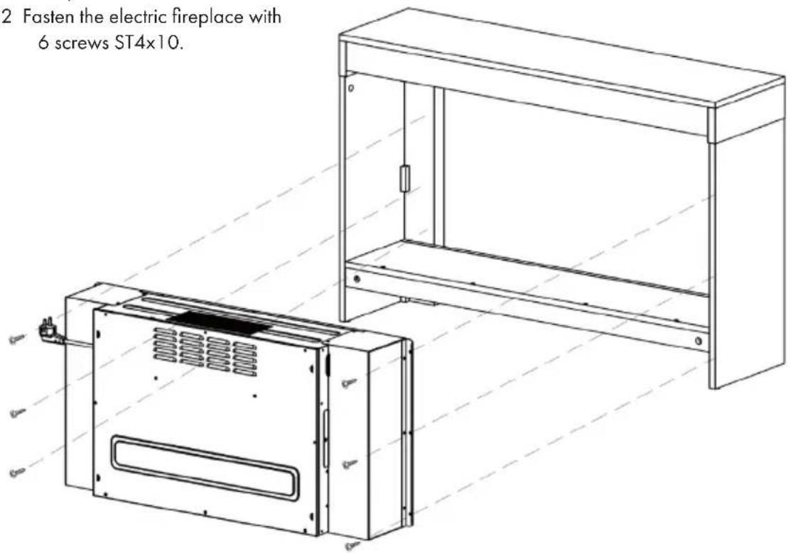
1 Place the electric fireplace in the mantle.
2 Fasten the electric fireplace with 6 screws ST4x10.
text_image
2 Fasten the electric fireplace with 6 screws ST4x10.INDIVIDUAL PARTS OVERVIEW (10038617 & 10038618)

text_image
Technical diagram of a microwave oven assembly with numbered components for identification and assembly.Parts list
| No. Description Pc. | ||
| 1 Upper plate 1 | ||
| 2 Lower plate 1 | ||
| 3 Left side plate 1 | ||
| 4 Right side plate 1 | ||
| 5 Bottom plate 2 | ||
| 6 Upper plate 1 | ||
| 7 Left plate 1 | ||
| 8 Right plate 1 | ||
| 9 Left box 1 | ||
| 10 Right box 1 | ||
| 11 | Electric fireplace | 1 |
Small parts
| No. Description Pc. | |||
| A | 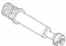 | Metal bolts | 32+1 |
| B |  | Metal pins | 32+1 |
| C |  | Dowel | 23+1 |
| D |  | Threaded bolt ST4x10 | 16+1 |
BEFORE ASSEMBLY (10038617 & 10038618)
text_image
D 10ASSEMBLY (10038617 & 10038618)
STEP 1
natural_image
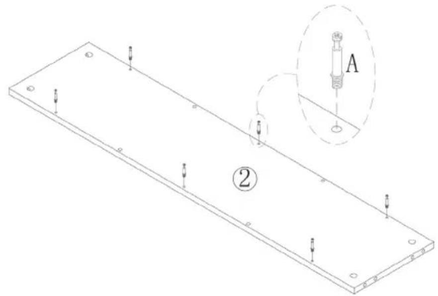
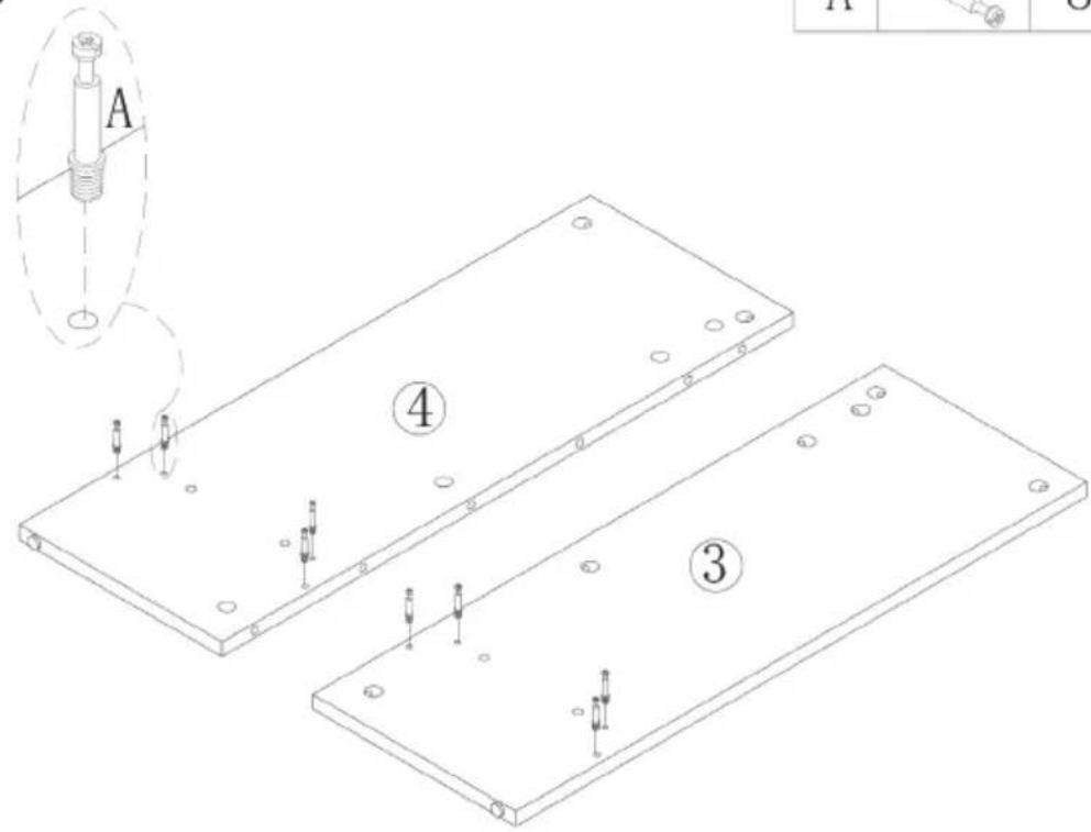
Technical line drawing of a rectangular plate with mounting holes and a magnified inset showing a labeled component 'A' (no text or symbols beyond labels)STEP 2
| B | 6 | |
| C | 4 |

text_image
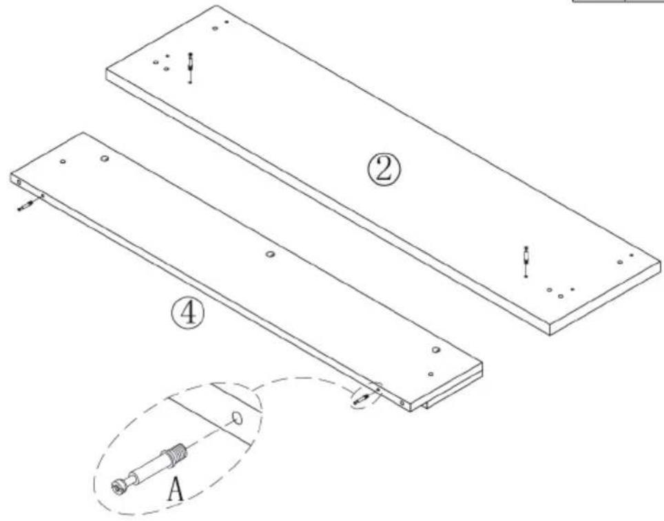
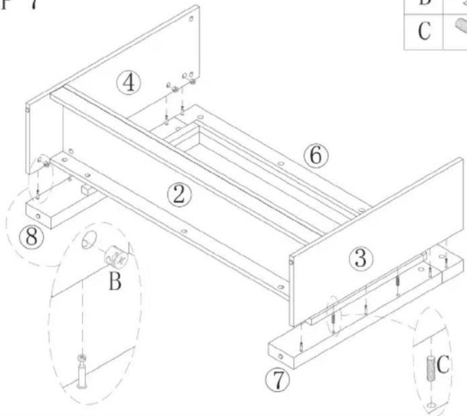
Technical diagram of a mechanical assembly with numbered components and exploded view, including labeled parts A, B, C and numbered parts 2, 5.STEP 3
| A | 8 |

text_image
A ④ ③STEP 4
| B | 8 | |
| C | 4 |
text_image
1E1-4 ④ ② ③ B C 4 A B C
text_image
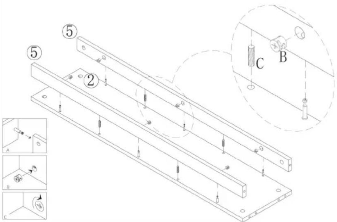
Technical diagram showing three labeled mechanical or structural components (A, B, C) with arrows indicating direction and a circular symbol labeled 'AB'.STEP 5
| A | 10 |
text_image
Technical diagram showing assembly of two parallel metal beams with labeled components and a magnified inset view labeled A.STEP 6
| B | 2 | |
| C | 4 |

text_image
Technical diagram of a mechanical assembly with labeled parts and exploded views, including numbered annotations and component callouts.STEP 7
| B | 8 | |
| C | 4 |

text_image
Technical diagram of a mechanical assembly with numbered components and labeled parts (A, B, C, D, E, F)STEP 8
| A | 8 |

natural_image
Isometric line drawing of a rectangular plate with mounting holes and a small inset showing a mechanical component labeled A (no text or symbols present)STEP 9
| B | 8 | |
| C | 7 |

text_image
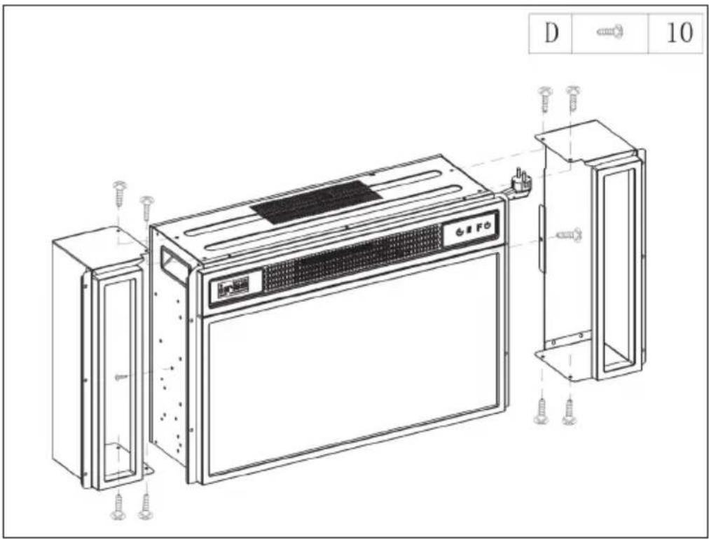
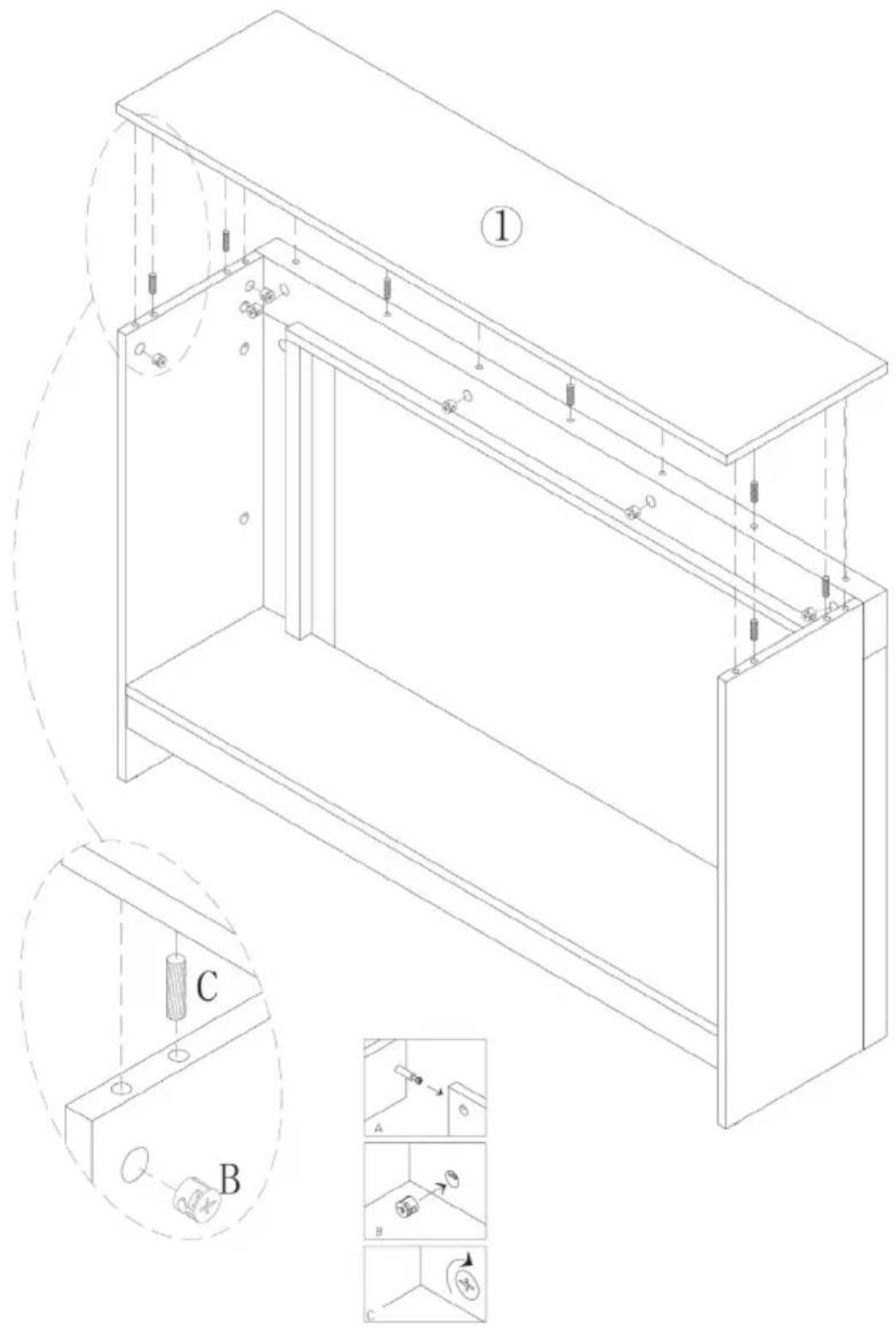
Technical diagram of a cabinet or enclosure with labeled components and assembly steps, including section B and detailed views A, B, C.STEP 10
| D | 6 |
1 Place the electric fireplace in the jacket.
2 Fasten the electric fireplace with 6 screws ST4x10.
text_image
2 Fasten the electric fireplace with 6 screws ST4x10.TROUBLESHOOTING
| Problem Possible cause Solution | ||
| "EE" is displayed on the screen. | Short circuit Contact customer service to have the thermostat sensor replaced | |
| "88" is displayed on the screen. | No warm air is blowing out and the fan is not working. | Set the power switch to the "off" position and wait at least 10 minutes. Then return the power switch to the "on" position. |
| The screen displays "OP". The open window warning (if the ambient temperature drops by 4 °C/ 8°F or more within 10 minutes and the temperature does not rise within 42 minutes) has been activated and the unit will switch off automatically. | Inspect the unit and ensure that the air inlets and outlets are not blocked as this could cause the unit to overheat. Unplug the device from the mains outlet for 30 minutes so that it can cool off. Afterwards, plug the power cord back into the mains socket and switch on the device. If the problem persists, contact customer service. | |
| No electricity, the logs are not glowing. | The mains plug is not plugged in. | Make sure the mains cord of the device is plugged into a 220-240V outlet. Press the on/off button several times and make sure that the power switch is in the "on" position. |
| No warm air is blowing out. | Cooling cycle Normal operation continues for a few minutes before switching off. The time depends on the current temperature. During this time, cold air is blown out. | |
| The thermostat setting prevents the heating function from being activated. | Adjust the temperature setting so that the thermostat is set higher than the current room temperature. | |
| The logs are glowing but there is no flame effect. | The flame effect is deactivated. | Press the flame button several times. |
| The flame effect is working but the heating function is not working, the ember bed lights up when the heating button is pressed. | The heating function is deactivated | With the unit switched on, press and hold the On/Off button for 10 seconds. As soon as the heating function has been activated again, the ember bed lights up several times. |
| The heating function is not working. | The safety switch has been activated. | Turn off the power switch, wait 15 minutes and turn it on again. |
| Check the fuse. If this is broken, the fuse must be replaced. | ||
| The remote control does not work when buttons are pressed. | No batteries. Replace the batteries. | |
| Poor signal transmission. Make sure that the distance between transmitter and receiver is not too great. | ||
| Press the buttons on the remote control with a smooth movement and gentle pressure. | ||
| Repeated pressing of the buttons in rapid succession may cause the transmitter to malfunction. | ||
| Distance too great. Operate | the remote control at a distance of less than 20 feet from the front of the unit; point the remote control at the control panel. | |
DISPOSAL CONSIDERATIONS
natural_image
Symbol of a trash bin crossed with a diagonal line, no text or numbers presentIf there is a legal regulation in your country regarding the disposal of electrical and electronic equipment, this symbol on the product or on the packaging indicates that this product must not be disposed of with household waste. Instead, it must be taken to a collection point for the recycling of electrical and electronic equipment. By disposing of this product in accordance with the regulations, you protect the environment and the health of those around you from negative consequences. For information on recycling and disposal of this product, contact your local government or household waste disposal service.
This product contains batteries. If there is a legal regulation in your country regarding the disposal of batteries, the batteries must not be disposed of in household waste. Consult your local regulations for the disposal of batteries. By disposing of this product in accordance with the regulations, you protect the environment and the health of those around you from negative consequences.
MANUFACTURER & IMPORTER (UK)
Manufacturer:
Chal-Tec GmbH, Wallstrasse 16, 10179 Berlin, Germany.
Importer for Great Britain:
Berlin Brands Group UK Ltd
PO Box 1145
Oxford, OX1 9UW
United Kingdom
Estimado cliente:
text_image
QR code image containing encoded data, no visible human-readable textÍNDICE
text_image
Interruptor principaltext_image
Technical diagram of a microwave oven with labeled components and exploded viewLista de piezas
text_image
Technical diagram of a microwave oven assembly with numbered components for identification and assembly reference.Lista de piezas
text_image
Technical diagram showing assembly steps of a mechanical component with labeled parts and numbered callouts
text_image
Technical diagram showing assembly steps of a mechanical component with labeled parts and corresponding exploded views.

text_image
Technical diagram of a mechanical assembly with labeled components and motion indicators| B | 3 | |
| C | 2 |
text_image
Diagram showing three labeled steps (A, B, C) of a mechanical or electrical component with directional arrows and circular symbols.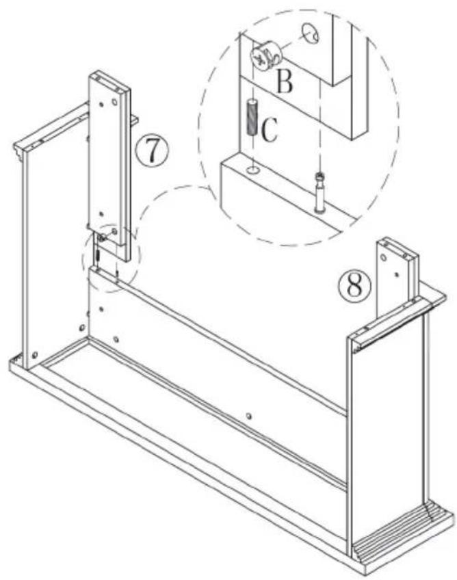
text_image
Technical diagram of a mechanical assembly with labeled components and an inset showing a component labeled B and C.| B | 2 | |
| C | 2 |
text_image
Diagram showing three steps (A, B, C) of a mechanical or electrical component with directional arrows and circular symbols indicating motion.
text_image
Technical diagram of a mechanical assembly with labeled parts and a magnified inset showing a screw and nut assembly.| D | 6 |

text_image
B 2 C 6 D 4 ② L C C B D C| E | 6 |
text_image
Technical diagram of a microwave oven assembly with numbered components for identification and assembly.Lista de piezas
text_image
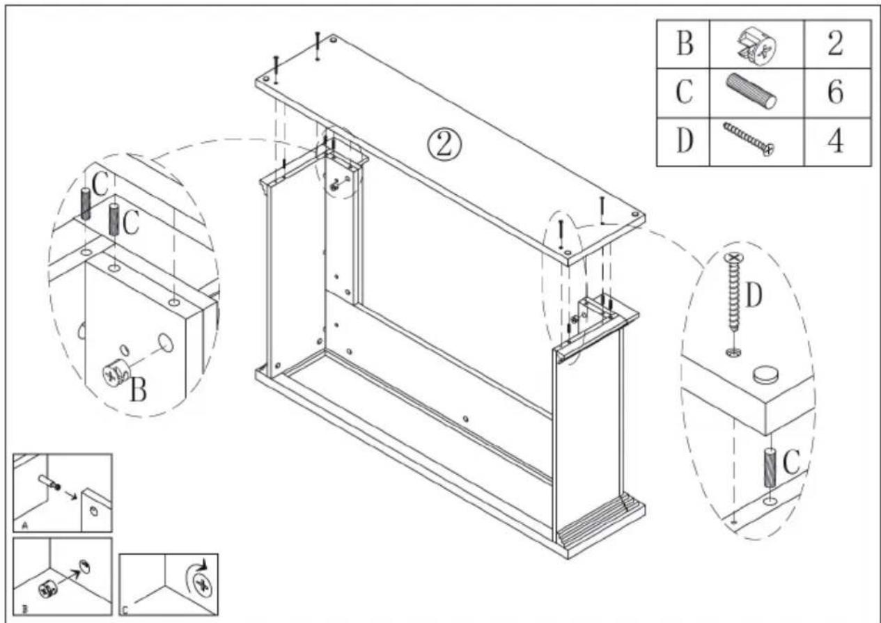
Technical diagram of a rectangular plate with labeled components and an inset showing a mechanical component labeled A.STEP 2
| B | 6 | |
| C | 4 |

text_image
Technical diagram of a mechanical assembly with numbered components and exploded view, including labeled parts A, B, C and internal features.STEP 3
| A | 8 |

text_image
A ④ ③STEP 4
| B | 8 | |
| C | 4 |

text_image
1E1-4 ④ ② ③ B C 4 A B C
text_image
Technical diagram showing three labeled mechanical or structural components (A, B, C) with directional arrows and circular symbols indicating motion or force.STEP 5
| A | 10 |

text_image
Technical diagram showing assembly of two parallel metal beams with labeled components and a magnified inset view labeled A.STEP 6
| B | 2 | |
| C | 4 |

text_image
Technical diagram of a mechanical assembly with labeled parts and exploded views, including numbered annotations and component callouts.STEP 7
| B | 8 | |
| C | 4 |

text_image
Technical diagram of a mechanical assembly with numbered components and labeled parts (A, B, C, 2, 3, 4, 6, 7, 8)STEP 8
| A | 8 |
natural_image
Isometric line drawing of a rectangular plate with mounting holes and a close-up inset showing a mechanical component labeled A (no text or symbols present)STEP 9
| B | 8 | |
| C | 7 |
text_image
Technical diagram of a cabinet or enclosure with labeled components and assembly details, including section 1, detail views A, B, C, and numbered callouts.STEP 10
| D | 6 |
natural_image
Symbol of a trash bin crossed with a diagonal line, representing no waste or discharge (no text or labels)Berlin Brands Group UK Ltd
PO Box 1145
Oxford, OX1 9UW
Reino Unido
Cher client, chère cliente,
text_image
QR code image containing encoded data, no visible human-readable textSOMMAIRE
FICHE DE DONNÉES PRODUIT
text_image
Technical diagram of a microwave oven with numbered components and labeled partsListe des pièces
text_image
Technical diagram of a mechanical assembly with numbered components for identification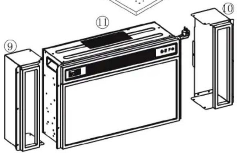
text_image
Technical diagram of a refrigerator with numbered parts and labeled componentsListe des pièces
text_image
Technical diagram showing assembly steps of a mechanical component with labeled parts and numbered callouts
text_image
Technical diagram showing assembly steps of a mechanical component with labeled parts and corresponding exploded views.| A | 4 |
text_image
Technical diagram showing two rectangular panels with labeled components and a magnified view of a mechanical component labeled A.| B | 3 | |
| C | 2 |

text_image
Technical diagram of a mechanical assembly with labeled components and motion indicators
text_image
Diagram showing three steps (A, B, C) of a mechanical or electrical component with directional arrows and circular symbols indicating motion.
text_image
Technical diagram of a mechanical assembly with labeled components and numbered parts| B | 2 | |
| C | 2 |

text_image
Diagram showing three steps (A, B, C) of a mechanical or electrical component with directional arrows and circular symbols indicating motion.
text_image
Technical diagram of a mechanical assembly with labeled parts and a magnified inset showing a screw and nut assembly.| D | 6 |

text_image
B 2 C 6 D 4 ② L C C B D C| E | 6 |
text_image
Technical diagram of a microwave oven assembly with numbered components for identification and assembly.Liste des pièces
text_image
Technical diagram of a rectangular plate with labeled components and an inset showing a mechanical component labeled A.STEP 2
| B | 6 | |
| C | 4 |
text_image
Technical diagram of a mechanical assembly with numbered components and exploded view, including labeled parts A, B, C and internal features.STEP 3
| A | 8 |

text_image
A ④ ③STEP 4
| B | 8 | |
| C | 4 |

text_image
1E1-4 ④ ② ③ B C 4 A B C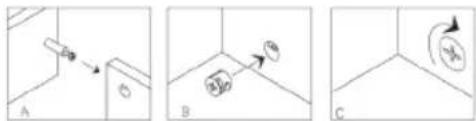
text_image
Technical diagram showing three labeled mechanical or structural components (A, B, C) with directional arrows and circular symbols.STEP 5
| A | 10 |

text_image
Technical diagram showing assembly of two parallel metal beams with labeled components and a magnified inset view labeled A.STEP 6
| B | 2 | |
| C | 4 |
text_image
Technical diagram of a mechanical assembly with labeled parts and exploded views, including numbered annotations and component callouts.STEP 7
| B | 8 | |
| C | 4 |

text_image
Technical diagram of a mechanical assembly with numbered components and labeled parts (A, B, C, D, E, F)STEP 8
| A | 8 |

natural_image
Isometric line drawing of a rectangular plate with mounting holes and a small inset showing a mechanical component labeled A (no text or symbols present)STEP 9
| B | 8 | |
| C | 7 |

text_image
Technical diagram of a cabinet or enclosure with labeled components and assembly details, including sectional views A, B, C.STEP 10
| D | 6 |
natural_image
Symbol of a trash bin crossed with a diagonal line, no text or numbers presentBerlin Brands Group UK Ltd
PO Box 1145
Oxford, OX1 9UW
United Kingdom
Gentile cliente,
text_image
QR code image containing encoded data, no visible human-readable textINDICE
text_image
Technical diagram of a microwave oven with labeled components and exploded viewLista delle parti
text_image
Technical diagram of a microwave oven assembly with numbered components for identificationLista delle parti
text_image
Technical diagram showing assembly steps of a mechanical component with labeled parts and numbered callouts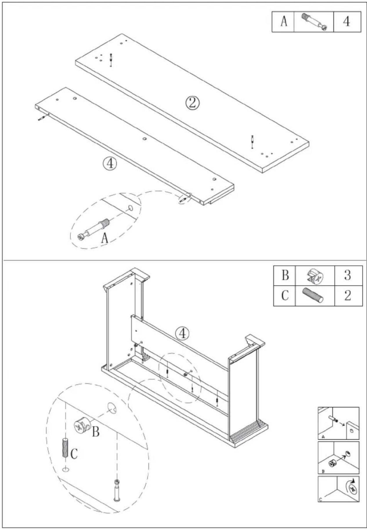
text_image
Technical diagram showing assembly steps of a mechanical component with labeled parts and corresponding exploded views.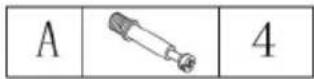

text_image
Technical diagram of a mechanical assembly with labeled components and motion indicators| B | 3 | |
| C | 2 |

text_image
Diagram showing three steps (A, B, C) of a mechanical or electrical component with directional arrows and circular symbols indicating motion.IT

text_image
Technical diagram of a mechanical assembly with labeled components and an inset showing a component labeled B and C.| B | 2 | |
| C | 2 |

text_image
Diagram showing three steps (A, B, C) of a mechanical or electrical component with directional arrows and circular symbols indicating motion.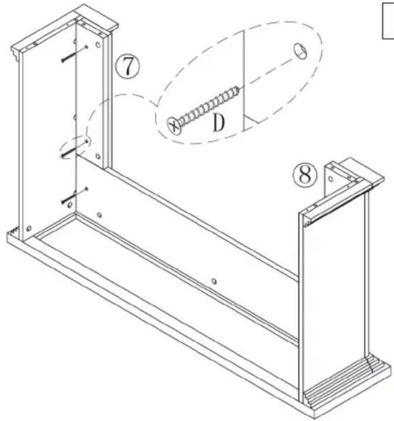
text_image
Technical diagram of a mechanical assembly with labeled parts and a magnified inset showing a screw and nut assembly.| D | 6 |

text_image
B 2 C 6 D 4 ② L C C B D C| E | 6 |
text_image
Technical diagram of a microwave oven assembly with numbered components for identification and assembly.Lista delle parti
text_image
Technical diagram of a rectangular plate with labeled components and an inset showing a mechanical component labeled A.STEP 2
| B | 6 | |
| C | 4 |

text_image
Technical diagram of a mechanical assembly with numbered components and exploded view, including labeled parts A, B, C and numbered parts 2, 5.IT
STEP 3
| A | 8 |
text_image
A ④ ③STEP 4
| B | 8 | |
| C | 4 |

text_image
1E1-4 ④ ② ③ B C 4 A B C
text_image
Technical diagram showing three labeled mechanical or structural components (A, B, C) with directional arrows and circular symbols indicating motion or force.STEP 5
| A | 10 |

text_image
Technical diagram showing assembly of two parallel metal beams with labeled components and a magnified inset view labeled A.STEP 6
| B | 2 | |
| C | 4 |

text_image
Technical diagram of a mechanical assembly with labeled parts and exploded views, including numbered annotations and component callouts.IT
STEP 7
| B | 8 | |
| C | 4 |
text_image
Technical diagram of a mechanical assembly with numbered components and labeled parts (A, B, C, D, E, F)STEP 8
| A | 8 |

natural_image
Isometric line drawing of a rectangular plate with mounting holes and a small inset showing a mechanical component labeled A (no text or symbols present)STEP 9
| B | 8 | |
| C | 7 |

text_image
Technical diagram of a cabinet or enclosure with labeled components and assembly details, including numbered parts and component callouts.STEP 10
| D | 6 |
natural_image
Symbol of a trash bin crossed with a diagonal line, no text or numbers presentPRODUTTORE E IMPORTATORE (UK)
Produttore:
Chal-Tec GmbH, Wallstraße 16, 10179 Berlino, Germania.
Berlin Brands Group UK Ltd
PO Box 1145
Oxford, OX1 9UW
United Kingdom

bar
| Category | Value | |---|---| | Category 1 | 100 | | Category 2 | 100 | | Category 3 | 100 | | Category 4 | 100 | | Category 5 | 100 | | Category 6 | 100 | | Category 7 | 100 | | Category 8 | 100 | | Category 9 | 100 | | Category 10 | 100 | | Category 11 | 100 | | Category 12 | 100 | | Category 13 | 100 | | Category 14 | 100 | | Category 15 | 100 | | Category 16 | 100 | | Category 17 | 100 | | Category 18 | 100 | | Category 19 | 100 | | Category 20 | 100 | | Category 21 | 100 | | Category 22 | 100 | | Category 23 | 100 | | Category 24 | 100 | | Category 25 | 100 | | Category 26 | 100 | | Category 27 | 100 | | Category 28 | 100 | | Category 29 | 100 | | Category 30 | 100 | | Category 31 | 100 | | Category 32 | 100 | | Category 33 | 100 | | Category 34 | 100 | | Category 35 | 100 | | Category 36 | 100 | | Category 37 | 100 | | Category 38 | 100 | | Category 39 | 100 | | Category 40 | 100 | | Category 41 | 100 | | Category 42 | 100 | | Category 43 | 100 | | Category 44 | 100 | | Category 45 | 100 | | Category 46 | 100 | | Category 47 | 100 | | Category 48 | 100 | | Category 49 | 100 | | Category 50 | 100 | | Category 51 | 100 | | Category 52 | 100 | | Category 53 | 100 | | Category 54 | 100 | | Category 55 | 100 | | Category 56 | 100 | | Category 57 | 100 | | Category 58 | 100 | | Category 59 | 100 | | Category 60 | 100 | | Category 61 | 100 | | Category 62 | 100 | | Category 63 | 100 | | Category 64 | 100 | | Category 65 | 100 | | Category 66 | 100 | | Category 67 | 100 | | Category 68 | 100 | | Category 69 | 100 | | Category 70 | 100 | | Category 71 | 100 | | Category 72 | 100 | | Category 73 | 100 | | Category 74 | 100 | | Category 75 | 100 | | Category 76 | 100 | | Category 77 | 100 | | Category 78 | 100 | | Category 79 | 100 | | Category 80 | 100 | | Category 81 | 100 | | Category 82 | 100 | | Category 83 | 100 | | Category 84 | 100 | | Category 85 | 100 | | Category 86 | 100 | | Category 87 | 100 | | Category 88 | 100 | | Category 89 | 100 | | Category 90 | 100 | | Category 91 | 100 | | Category 92 | 100 | | Category 93 | 100 | | Category 94 | 100 | | Category 95 | 100 | | Category 96 | 100 | | Category 97 | 100 | | Category 98 | 100 | | Category 99 | 100 | | Total (Total) = [sum of bars] / [values] * (sum of bars + bars) * (sum of bars + bars) * (sum of bars + bars). The values in the table represent the sum of the bars and the corresponding sum of the bars. There is no additional data series or categories specified in the code.