
Galeras Smart - Fireplace Klarstein - Free user manual and instructions
Find the device manual for free Galeras Smart Klarstein in PDF.

| Product type | Electric fireplace |
| Brand | Klarstein |
| Model | Galeras Smart |
| Heating power | 900 W (low) / 1800 W (high) |
| Power supply | 220-240 V ~ 50 Hz |
| Article numbers | 10038687, 10038688, 10038689, 10038690, 10045616, 10045617, 10046436, 10046437, 10046438, 10046439 |
| Package contents | 1x Fireplace, 1x Wall bracket with screws, 1x Remote control, 1x Top support, 1x Bottom support, screws, instruction manual, decorative glass, white pebbles |
| Flame effect | 5 brightness levels, red and blue colors |
| Control | Control panel, remote control, smartphone app (specific models) |
| Timer | Programmable from 1 to 8 hours, day/hour setting |
| Temperature range | 18 to 30 °C (switchable to °F) |
| Safety | Automatic shutoff in case of overheating, child lock, safety distance 1 m |
| Maintenance | Dust with vacuum cleaner or damp cloth, no abrasive products |
| LED bulbs | Lifespan 100,000 hours, replacement by a qualified electrician |
| Installation | Wall-mounted or recessed, minimum height 30 cm from floor, distance to ceiling 100 cm |
Frequently Asked Questions - Galeras Smart Klarstein
User questions about Galeras Smart Klarstein
0 question about this device. Answer the ones you know or ask your own.
Ask a new question about this device
Download the instructions for your Fireplace in PDF format for free! Find your manual Galeras Smart - Klarstein and take your electronic device back in hand. On this page are published all the documents necessary for the use of your device. Galeras Smart by Klarstein.
USER MANUAL Galeras Smart Klarstein
Note: The device is not suitable for use as a primary heat source.
bar
| Category | Value | |---|---| | Category 1 | 100 | | Category 2 | 100 | | Category 3 | 100 | | Category 4 | 100 | | Category 5 | 100 | | Category 6 | 100 | | Category 7 | 100 | | Category 8 | 100 | | Category 9 | 100 | | Category 10 | 100 | | Category 11 | 100 | | Category 12 | 100 | | Category 13 | 100 | | Category 14 | 100 | | Category 15 | 100 | | Category 16 | 100 | | Category 17 | 100 | | Category 18 | 100 | | Category 19 | 100 | | Category 20 | 100 | | Category 21 | 100 | | Category 22 | 100 | | Category 23 | 100 | | Category 24 | 100 | | Category 25 | 100 | | Category 26 | 100 | | Category 27 | 100 | | Category 28 | 100 | | Category 29 | 100 | | Category 30 | 100 | | Category 31 | 100 | | Category 32 | 100 | | Category 33 | 100 | | Category 34 | 100 | | Category 35 | 100 | | Category 36 | 100 | | Category 37 | 100 | | Category 38 | 100 | | Category 39 | 100 | | Category 40 | 100 | | Category 41 | 100 | | Category 42 | 100 | | Category 43 | 100 | | Category 44 | 100 | | Category 45 | 100 | | Category 46 | 100 | | Category 47 | 100 | | Category 48 | 100 | | Category 49 | 100 | | Category 50 | 100 | | Category 51 | 100 | | Category 52 | 100 | | Category 53 | 100 | | Category 54 | 100 | | Category 55 | 100 | | Category 56 | 100 | | Category 57 | 100 | | Category 58 | 100 | | Category 59 | 100 | | Category 60 | 100 | | Category 61 | 100 | | Category 62 | 100 | | Category 63 | 100 | | Category 64 | 100 | | Category 65 | 100 | | Category 66 | 100 | | Category 67 | 100 | | Category 68 | 100 | | Category 69 | 100 | | Category 70 | 100 | | Category 71 | 100 | | Category 72 | 100 | | Category 73 | 100 | | Category 74 | 100 | | Category 75 | 100 | | Category 76 | 100 | | Category 77 | 100 | | Category 78 | 100 | | Category 79 | 100 | | Category 80 | 100 | | Category 81 | 100 | | Category 82 | 100 | | Category 83 | 100 | | Category 84 | 100 | | Category 85 | 100 | | Category 86 | 100 | | Category 87 | 100 | | Category 88 | 100 | | Category 89 | 100 | | Category 90 | 100 | | Category 91 | 100 | | Category 92 | 100 | | Category 93 | 100 | | Category 94 | 100 | | Category 95 | 100 | | Category 96 | 100 | | Category 97 | 100 | | Category 98 | 100 | | Category 99 | 100 | | Total (Total) = [sum of bars] / [values] * (sum of bars + bars) * (sum of bars + bars) * (sum of bars + bars) * (sum of bars + bars) * (sum of bars + bars) * (sum of bars + bars) * (sum of bars + bars) * (sum of bars + bars) * (sum of bars + bars) * (sum of bars + bars) * (sum of bars + bars) * (sum of bars + bars) * (sum of bars + bars) * (sum in brackets) * (sum in brackets) * (sum in brackets) * (sum in brackets) * (sum in brackets) * (sum in brackets) * (sum in brackets) * (sum in brackets) * (sum in brackets) * (sum in brackets) * (sum in brackets) * (sum in brackets) * (sum in brackets) * (sum in brackets) * (sum in brackets) * (sum in brackets) * (sum in brackets) * (total).* (sum in brackets) * (sum in brackets) * (sum in brackets) * (sum in brackets) * (sum in brackets) * (sum in brackets) * (sum in brackets) * (sum in brackets) * (sum in brackets) * (sum in brackets) * (sum in brackets) * (sum in brackets) * (total).* (sum in brackets) * (sum in brackets) * (sum in brackets) * (sum in brackets)INHALTSVERZEICHNIS
natural_image
Exploded view diagram of a smart air conditioner unit showing internal components and assembly (no text or labels)natural_image
Technical line drawing of a server rack unit with front panel and side panel, showing dimensions (no text or symbols)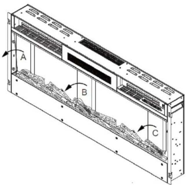
natural_image
Diagram of a server rack with ventilation grilles and a monitor, showing red directional arrows indicating movement (no text or symbols)natural_image
Isometric view of a rectangular block with a dashed internal line and three small circular markers on its side (no text or symbols)natural_image
Diagram showing a device with red wire routing through a panel, and a magnified view of the internal structure (no text or symbols)natural_image
Technical line drawing of a multi-chamber industrial enclosure with ventilation grilles and mounting holes (no text or symbols)natural_image
Technical line drawing of a server rack unit with mounting brackets and ventilation grilles (no text or symbols)natural_image
Isometric line drawing of a server rack unit with internal components and mounting brackets (no text or symbols)natural_image
Technical line drawing of a computer monitor with ventilation slots and a circular component (no text or symbols)INSTALLATION DES DEKORATIVEN ZUBEHÖRS
natural_image
Technical line drawing of a multi-chamber electronic device casing with internal components and mounting holes (no text or symbols)natural_image
Technical line drawing of a server rack unit with internal components and mounting holes (no text or symbols)natural_image
Technical line drawing of a server rack with ventilation grilles and a coiled cable (no text or symbols)natural_image
Symbol of a trash bin crossed with a diagonal line, no text or numbers presentBerlin Brands Group UK Limited
PO Box 42
272 Kensington High Street
London, W8 6ND
United Kingdom
PRODUKTDATENBLATT
Congratulations on purchasing this device. Please read the following instructions carefully and follow them to prevent possible damages. We assume no liability for damage caused by disregard of the instructions and improper use. Scan the QR code to get access to the latest user manual and more product information.

CONTENTS
Safety Instructions 34
Package Contents 35
Installation 36
Control Panel and Remote Control 50
Operation (Basic Functions) 52
Operation via Remote Control 52
Protective Functions 54
Device Control by Smartphone 55
Cleaning and Maintenance 57
Troubleshooting 57
Disposal Considerations 58
Manufacturer & Importer (UK) 58
Product Data Sheet 59
TECHNICAL DATA
| Item number | 10038687, 10038688, 10038689, 10038690, 10045616, 10045617 10046436, 10046437, 10046438, 10046439 |
| Power supply 220-240 V ~ 50 Hz | |
| Power 900 W / 1800 W |
SAFETY INSTRUCTIONS
- Before use, check the voltage information on the rating plate and only connect the device to sockets that correspond to the nominal voltage of the device.
- If the power cord is damaged, have it replaced by a trained professional.
- Do not place the fireplace directly under the mains socket.
- Keep a distance of one metre from combustible materials such as furniture, curtains or similar.
- Use the appliance out of the reach of children. Children may only operate the device under supervision.
- The appliance is intended for use in the home and similar environments only. It is not intended for commercial use.
- Do not use the device if it malfunctions or has been damaged in any way.
• Repairs may only be carried out by trained specialists. - Incorrectly or independently performed repairs pose a risk of injury.
- Do not run the power cord under carpets or rugs.
- Make sure that the power cord does not come into contact with sharp edges or hot surfaces.
- To prevent overheating, do not cover the fireplace.
- Do not use the appliance with an external timer, a remote controlled socket or any other device that automatically turns the fireplace on and off.
- Do not immerse the device in water or other liquids.
- Do not use the appliance near bathtubs, showers or swimming pools.
- Do not use the device outdoors.
- Do not use the device with wet hands.
- Do not use the appliance on or near hot surfaces
- Do not use the device with a damaged power cord.
- Before cleaning, unplug the appliance from the wall outlet and allow it to cool completely.
- Do not use abrasive cleaners for cleaning.
- Only use accessories that are expressly approved for this purpose by the manufacturer.
- Children from the age of 8 years and mentally, sensory and physically impaired persons may only use the device if they have been informed in detail about the functions and safety precautions by a supervisor responsible for them beforehand and understand the associated risks.
- Make sure that children do not play with the appliance.
CAUTION
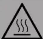
Risk of burns! Some parts of the appliance can become very hot. Be careful not to burn yourself or your children with it.
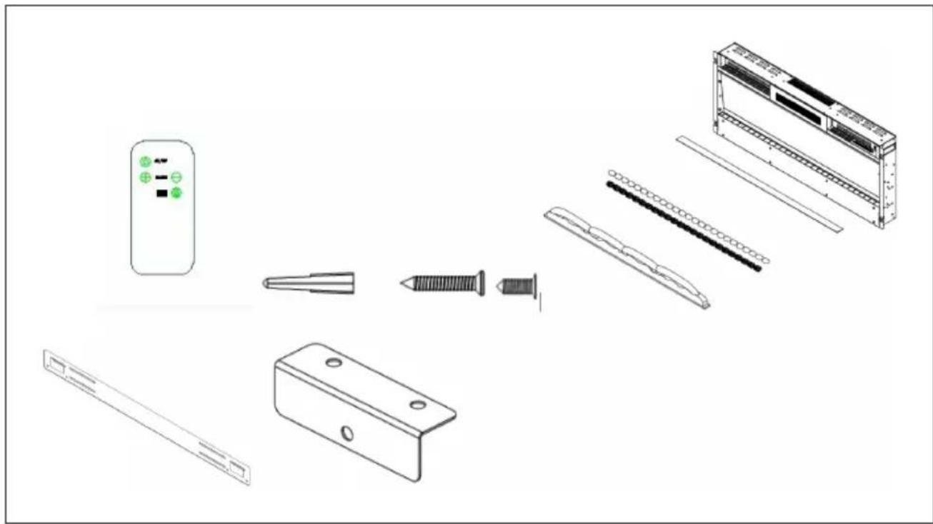
PACKAGE CONTENTS
natural_image
Exploded view diagram of a smart air conditioner unit showing internal components and assembly (no text or labels)1x Electric fireplace
1x Wall bracket with screws
1x Remote control
1x Upper bracket
1x Lower bracket
8x Screws (4 x 30 mm) for fixing the upper bracket - for models 10038687, 10038688, 10038689, 10038690, 10045616
13x Screws (4 x 30 mm) for fixing the upper bracket - for model 10045617
2x Screws (4 x 8 mm) for fixing the safety glass
2x Screws (4 x 8 mm) for fixing the lower bracket
1x Screws (4 x 30 mm) for fixing the lower bracket
1x Operating instructions
1x Bag with glass
1x Bag of white pebbles
INSTALLATION
First steps
- Remove the unit from the packaging.
- Remove all packaging materials from the unit.
- Place the packing materials in the packaging and either store them safely or dispose of them properly.
Storage of the packaging and accessories
- Keep all packaging materials until you have checked that the scope of delivery is complete.
- The scope of delivery includes small parts that must be kept out of the reach of children.
- It is recommended that you collect all small parts included in the delivery in a box after opening the packaging so that you do not lose any parts.
Important instructions for installation
Note: Do not insert the power cord of the appliance into the wall socket until you have installed the appliance correctly on the wall and read the entire instruction manual
- Observe the minimum distances specified in the operating instructions.
- When installing the appliance on the wall, make sure that no cables or wires in the wall are damaged when drilling the holes.
• Take care when drilling the holes.
WALL INSTALLATION
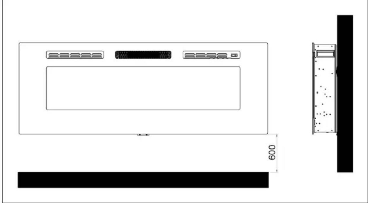
- The appliance must be installed at a minimum height of 30 cm. The minimum distance between the appliance and the ceiling should be 100 cm. Mount the wall bracket horizontally on the wall and lay the mains cable on the lower right side of the fireplace.
- A minimum distance of 60 cm from the bottom of the fireplace to the floor is recommended for optimal visibility of the fuel decoration (for recommended minimum distances, see figure 1).
Figure 1
natural_image
Technical line drawing of a server rack unit with ventilation grilles and a wall-mounted unit, showing dimension 600 (no text or symbols)- Mark the position of the four upper screws for optimal visibility. The mounting position on the wall must correspond to the specified mounting dimensions (see figure 2).
Note: Use a spirit level to make sure the bracket is level and mark the positions of the holes.
Preparation
- Remove the four silver screws from the sides of the fireplace, 2 screws on each side. Remove the two screws at the front of the fireplace. Remove the safety glass by lifting it out of the brackets on the side (see figure 2) and remove the foam from inside the fireplace.
Figure 2


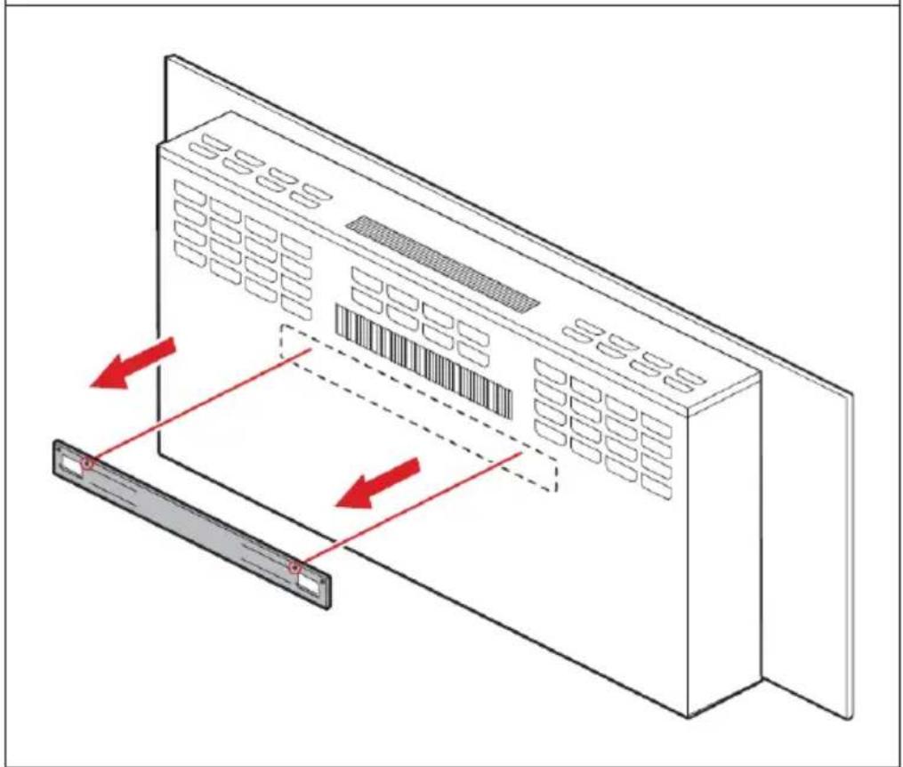
- Remove the screws from the wall bracket at the back of the fireplace and remove the wall bracket (see figure 3).
Figure 3
natural_image
Diagram of a server rack with ventilation grilles and a monitor, showing red directional arrows indicating movement (no text or symbols)EN
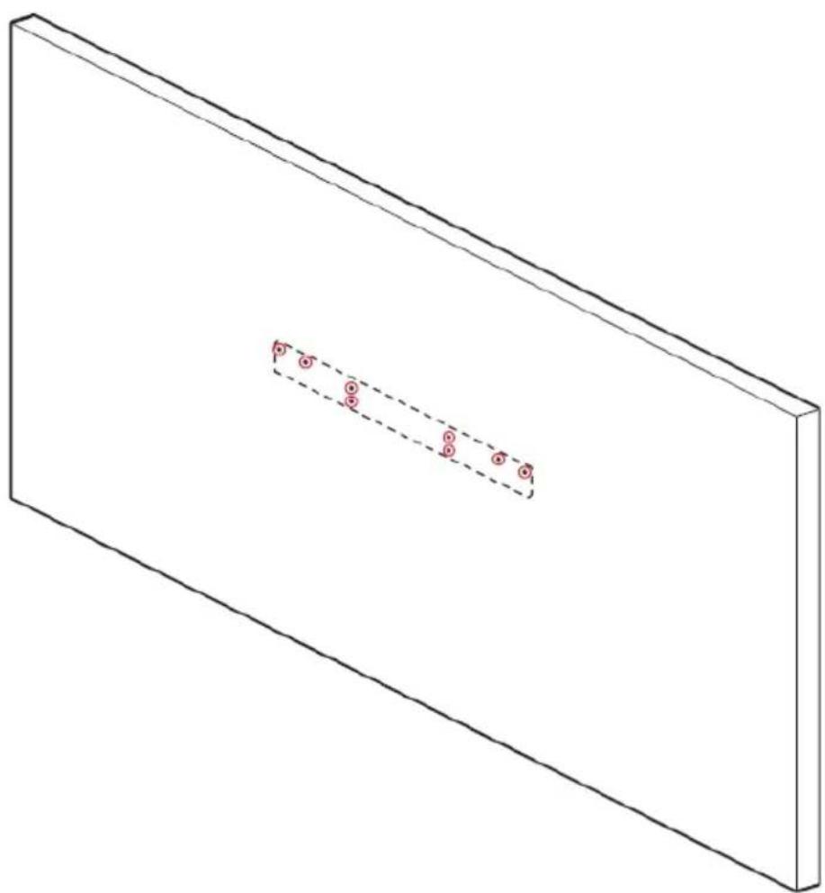
- Hold the wall bracket against the wall and mark the positions where the 8 screw holes should be. Make sure that the bracket is level.
- Use an electric drill and drill 8 size 6 holes in the marked places.
Figure 4
natural_image
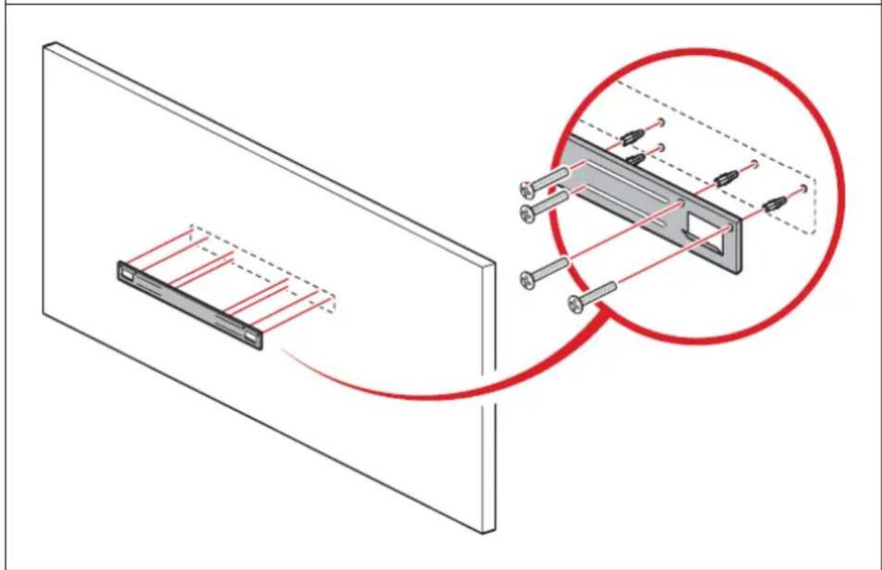
Isometric view of a rectangular plate with a dashed internal line and three small circular markers on the side (no text or symbols)- Insert eight dowels (4 x 30 mm) into the holes and fix the wall bracket to the wall with 8 screws (4 x 30 mm) (see figure 5).
Figure 5
natural_image
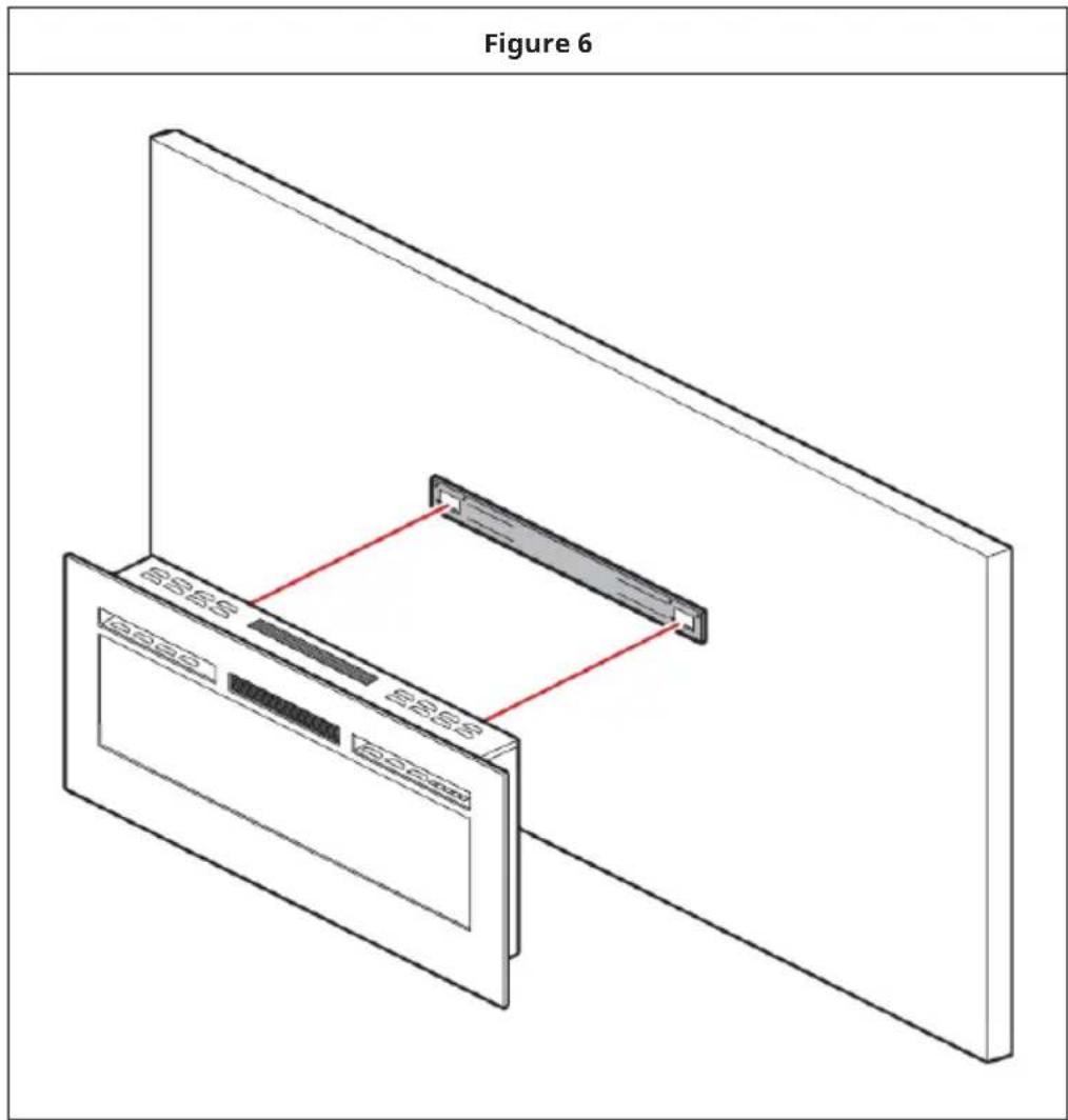
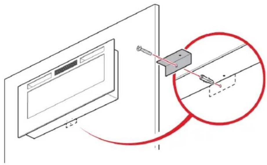
Diagram showing a device with red lines and pins, connected to a magnified view of its internal structure (no text or symbols present)- Lift the fireplace and place it carefully on the wall bracket. Make sure that the fireplace is securely latched to the wall bracket (see figure 6).
- Insert a dowel into the drilled hole and fix the lower bracket with a screw (4 x 30 mm) (see figure 7).
Figure 7
natural_image
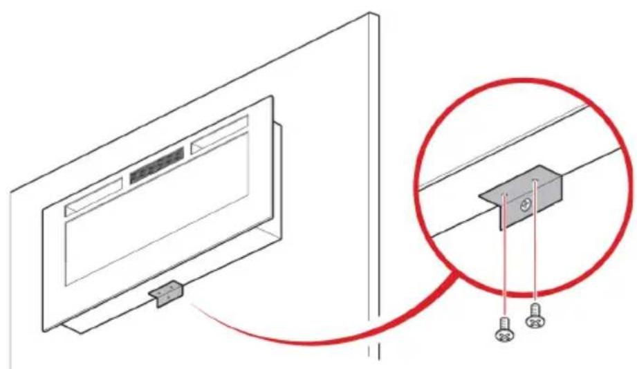
Diagram showing a monitor mounted on a wall with a close-up of a mechanical component, no text or symbols present.- Secure the lower bracket to the chimney with two screws (4 x 30 mm) (see figure 8).
Figure 8
natural_image
Diagram showing a monitor mounted on a wall connected to a cable with two connectors, highlighting the cable connection (no text or symbols present)- Place the glass or pebbles in the fuel bed. First remove the glass from the appliance. Now place the stones in the fuel bed.
Figure 9
natural_image
Technical line drawing of a multi-chamber industrial enclosure with ventilation grilles and mounting holes (no text or symbols)- Place the safety glass at the front of the fireplace, aligning the slots in the bracket on each side of the glass with the lugs on the sides of the fireplace (see figure 10).
Note: 2 people are required for this installation step.
Figure 10
natural_image
Technical line drawing of a server rack unit with mounting brackets and ventilation grilles (no text or symbols)• Fix the safety glass with four white screws (4 x 8 mm on both sides).
Manual operation
- The switches are located on the centre right side of the unit. The standby switch must be switched on first.
Note: Read the operating instructions carefully and keep them for future use.
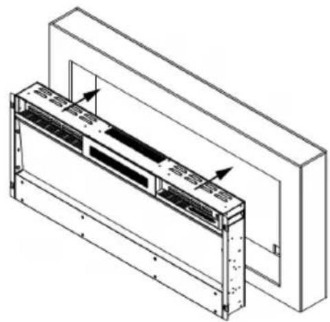
WALL INSTALLATION
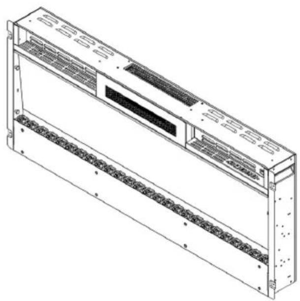
- First remove the safety glass from the appliance. With the help of another person, carefully place the fireplace in the wall cut-out (see figure 11).
Figure 11
natural_image
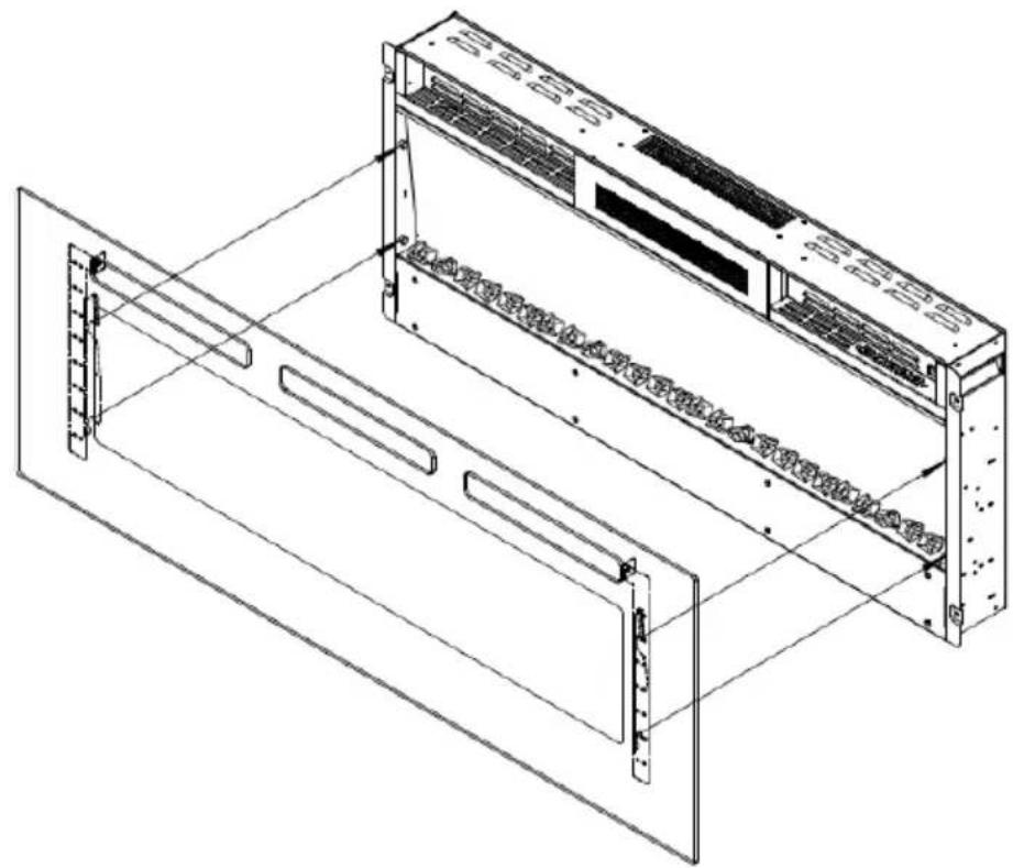
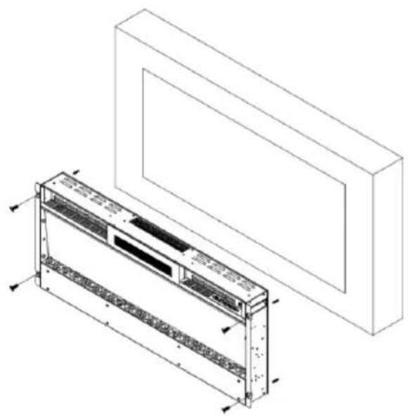
Technical line drawing of a mechanical assembly with mounting brackets and internal components (no text or symbols)- For optimal visibility, mark the positions of the left and right screws on the wall in accordance with the screw holes on the fireplace (see figure 12).
Figure 12
natural_image
Technical line drawing of a modular air conditioner unit with mounting bracket (no text or symbols)- Place the glass or white pebbles in the fuel bed.
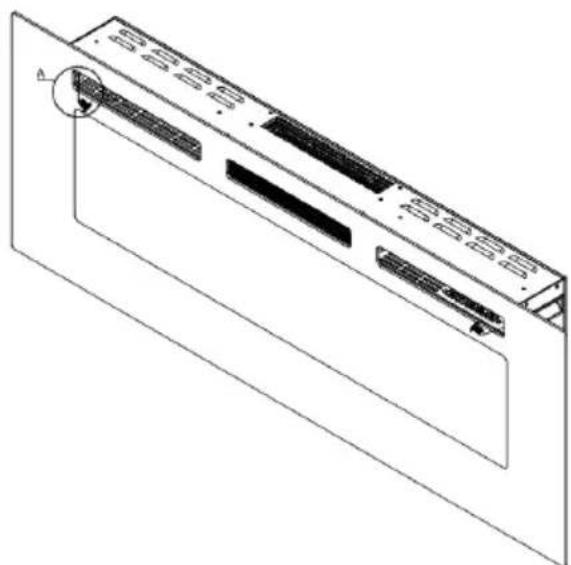
- Place the safety glass at the front of the fireplace, aligning the slots in the bracket on each side of the glass with the lugs on the sides of the fireplace (see figure 13).
Note: 2 people are required for this installation step.
Figure 13

natural_image
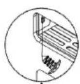
Isometric line drawing of a server rack unit with internal components and mounting brackets (no text or symbols)- Fix the safety glass with 2 screws (4 x 8 mm) included in the delivery (see figure 15).
Figure 15
natural_image
Technical line drawing of a computer monitor with ventilation slots and a circular component (no text or symbols)INSTALLING THE DECORATIVE ACCESSORIES
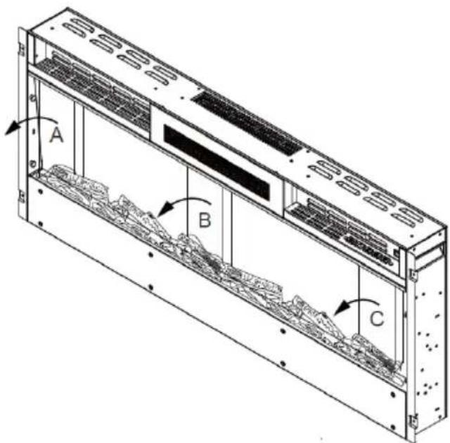
Install logs/glass blocks and pebbles in the fuel bed
Note: Make sure that the installation corresponds to the fuel bed you have purchased or selected.
- The safety glass must be removed from the appliance and the appliance fixed in its final position before the logs or stones can be installed.
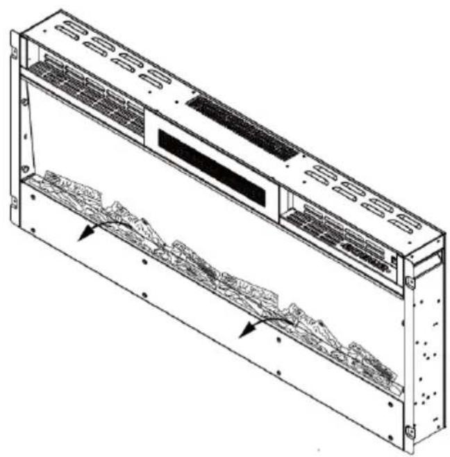
- If the fireplace is delivered with logs, take them out of the packaging and place them in the designated place in the fireplace (see figure 16).
Figure 16
natural_image
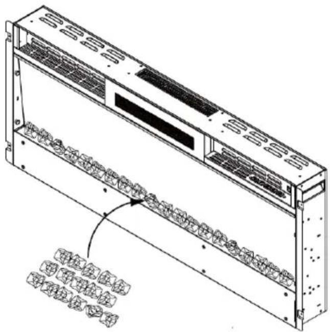
Technical line drawing of a server rack unit with ventilation grilles and internal components (no text or symbols)- If the appliance is supplied with glass blocks, note that the glass blocks may have fine oil residues which must be removed by thorough cleaning before installation. Remove the residues with a mild detergent and then rinse the glass blocks with clear water. Dry the glass blocks before placing them in their designated place in the fireplace.
Figure 17
natural_image
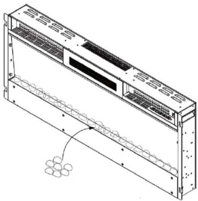
Technical line drawing of a server rack unit with internal components and mounting holes (no text or symbols)- Carefully place the glass or pebbles in the bottom compartment at the front of the appliance. Make sure that the decorative stones are evenly distributed (see figure 18).
Figure 18
natural_image
Technical line drawing of a server rack with ventilation grilles and a coiled cable (no text or symbols)CONTROL PANEL AND REMOTE CONTROL
Control panel
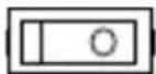
Flames On/Off Power
switch
Timer Temperature Heating
level
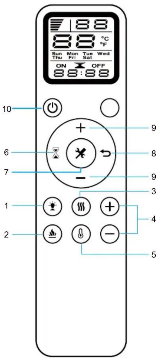
Remote control
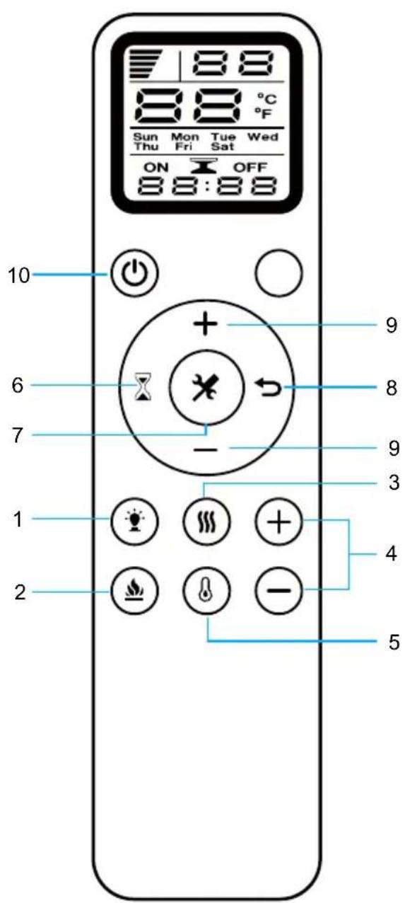
| Remote control buttons | |
| 1 | Colour |
| 2 | Flames |
| 3 | Heating |
| 4 | Temperature: Increase (+) Lower (-) |
| 5 | Temperature |
| 6 | Timer |
| 7 | Settings |
| 8 | Delete |
| 9 | Timer: On (+) From (-) |
| 10 | On/Off |
Note: When using the remote control, make sure it is pointed at the receiver on the appliance.
Replacing the batteries of the remote control
If the remote control no longer works or its range is limited, you should replace the battery.
- The battery compartment is located on the back of the remote control.
- Press and slide the battery compartment cover down. Insert a type AAA battery into the battery compartment. Make sure that the "+" and "-" markings on the battery and in the battery compartment match.
- Put the battery cover back on.
Notes:
- Do not use old and new batteries at the same time.
- Do not use rechargeable silver oxide batteries for the remote control.
- Do not mix alkaline batteries with standard batteries (carbon-zinc) or rechargeable batteries (nickel-cadmium).
- Never throw batteries into a fire. Inadequate disposal of batteries can cause them to leak or explode.
OPERATION (BASIC FUNCTIONS)
Note: The appliance can be operated either by the switches located on the upper right side of the appliance or by the remote control included in the delivery.
- The standby switch located on the centre right side of the unit must be switched on first.
- It takes some time for the receiver to answer the transmitter. Do not press the buttons more than once within 2 seconds to ensure correct operation.
- Press the ON/OFF button on the remote control once to switch on the appliance and the flame effect.
- Press the FLAME button to adjust the flame brightness. The appliance has 5 brightness levels that are cycled through in sequence and the off setting. Each time you press the FLAME button, the flame intensity decreases.
- Press the HEAT button once to set the low heat level (900 W). Press the HEAT button twice to set the high heat level (1800 W). If you press the button again, the heating function is switched off.
- The appliance has 12 different temperature settings from 18-30 °C, which you can set in the order 30 °C > ... > 18 °C. Press and hold the TEMPERATURE button for 3 seconds to change from Celsius (°C) to Fahrenheit (°F) (setting range: 64-88 °F).
- Timer setting: Press the TIMER key several times to cycle through the different timer settings in succession : 1 h > ... > 8 h > Off.
Switching on the appliance
- Press the ON/OFF button on the remote control once to switch on the appliance and the flame effect.
- After you have inserted the AAA battery into the remote control, "10:00" and "MON" are displayed on the LED screen at the first start.
- Press the ON/OFF button to switch on the appliance "H0" is displayed on the LED screen.
Set heating level
- Press the HEAT button to switch on the heating function. Pressing the button once activates the low heating level (900 W). "H1" is displayed on the LED screen. If you press the button twice, the high heating level (1800 W) is activated. "H2" is displayed on the screen. If you press the button again, the heating function is switched off.
Setting the temperature
- When you press the TEMPERATURE button, the temperature initially shows 18 °C. Press the HIGHER(+) button to increase the temperature. Press the LOWER (-) button to lower the temperature. Pressing the TEMPERATURE button again will reset the temperature setting to the original heating function (for example, if the setting was previously "H0", it will be reset to "H0".
- Press and hold the TEMPERATURE button for about 3 seconds to change from Celsius (°C) to Fahrenheit (°F).
Setting the flame colour
- Press the COLOUR button on the remote control to change the flame colour. If you press the button once, the colour changes from red to blue. If you press the button twice, the colour changes from blue to red. If you press the button a third time, the colour turns red again.
Setting the flame brightness
- Press the FLAME button, for dimmer mode. Each time the button is pressed, the flame intensity decreases. The appliance has 5 brightness levels that are scrolled through in sequence each time the button is pressed: L5 > L4 > L3 > L2 > L1. The brightness levels are not displayed on the LED screen, only on the appliance.
Setting the timer
- Press the Timer button. When you press the TIMER button for the first time, "MON" flashes on the digital screen. Use the UP (+) and DOWN (-) buttons to set the timer for the weekdays Monday to Sunday.
| Mon | Tues | Wed | Thurs | Fir | Sat | Sun |
- When you press the SETTINGS button, "HOUR" flashes on the digital screen. Use the UP (+) or DOWN (-) buttons to set the hours between 00:00 and 24:00.
- Press the SET button a second time to set the minutes. The minute display flashes on the digital screen. Use the UP (+) or DOWN (-) buttons to set 00:00 - 12:00 AM to 13:00 - 24:00 PM. If you press the SETTINGS button a third time, all timer settings are confirmed.
Activate/deactivate timer and temperature setting
-
When you press the TIMER button, "MON" flashes. Press the SETTINGS button three times. "ON" flashes on the screen. Set the time at which the timer is to be activated. Use the UP (+) or DOWN (-) buttons to set the hours and minutes. When you press the DELETE button, the timer setting is deleted.
-
When you press the SETTINGS button, "OFF" flashes on the screen. Set the time at which the timer is to be deactivated. Use the UP (+) or DOWN (-) buttons to set the hours and minutes, If you press the DELETE button, the timer setting is deleted. When you press the SETTINGS button again, the digital screen shows "18". Use the HIGHER(+) and LOWER(-) buttons to adjust the temperature. Press the HEAT button. Pressing the button once activates the low heating level (900 W). "H1" is displayed on the LED screen. If you press the button twice, the high heating level (1800 W) is activated. "H2" is displayed on the screen. If you press the button again, the heating function is switched off.
-
When you press the SETTINGS button again, "TUES" flashes on the digital screen. Set the start time for Tuesday. To do this, use the HIGHER (+) and LOWER (-) buttons. As soon as you press the SETTINGS button, "OFF" flashes on the screen. Set the end time for Tuesday. To do this, use the HIGHER (+) and LOWER (-) buttons. When you press the SETTINGS button again, the screen displays "18". Adjust the temperature for Tuesday using the HIGHER (+) and LOWER (-) buttons. Press the HEAT button. Pressing the button once activates the low heating level (900 W). "H1" is displayed on the LED screen. If you press the button twice, the high heating level (1800 W) is activated. "H2" is displayed on the screen. If you press the button again, the heating function is switched off.
-
Follow step 2 to make the settings for all other weekdays.
PROTECTIVE FUNCTIONS
Temperature warning function
If the appliance is in operation and the indoor temperature drops by more than 5 °C within 10 minutes, the appliance beeps three times to warn you. The heating function is then deactivated. You should check whether windows are open.
Safety shutdown
- This appliance is equipped with a safety cut-out that is activated if the appliance overheats (for example, due to blocked air vents). For safety reasons, if the safety shutdown has been triggered, the appliance is not automatically reset.
- To reset the appliance, disconnect it from the power supply for at least 15 minutes. Afterwards, plug the power cord back into the wall socket and switch on the appliance.
DEVICE CONTROL BY SMARTPHONE
For items 10046436, 10046437, 10046438, 10046439
If you integrate the device into your home WiFi, you can conveniently operate it via the associated Klarstein app. The app not only allows you to remotely control the device via your smartphone, but also gives you access to recipes and additional information.
Follow these steps to connect your smartphone to your Klarstein device:
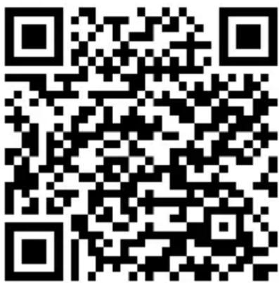
- Download the Klarstein app first by scanning the QR code with your smartphone (see below), or download it directly from App Store or Google Play.
- Make sure your smartphone is connected to the same WiFi network that your Klarstein device is to be connected to.
- Open the Klarstein app.
- Sign in to your account. If you do not have an account, sign up in the Klarstein app.
- Press and hold the standby button on the remote control or on the device. Follow the instructions from the app.
App Download
Use the scan function of your smartphone to scan the QR code and save the app on your smartphone.
Note: The app provides further information on how to use the app and help on how to connect to your device as soon as you open it for the first time.
| iOS Android | |
 |  |
Troubleshooting connection problems
If your Klarstein device cannot be found in the WLAN, check the following:
- The device is not plugged in. Make sure that your device is plugged into an electric socket.
- The device is not in pairing mode. Make sure that the WiFi indicator (LED) on the smart device control panel is blinking as described in the 'Reset WiFi settings' instruction of your smart device (instructions are usually available on device connection process).
- The WiFi access point does not operate on 2.4 GHz. Make sure that your access point operates on 2.4 GHz band and you have a separate SSID on 2.4 GHz band. If you are not sure about the operating band of your access point, please contact your internet provider company.
Important: please note that if your WiFi router is dual band - operating on both 2.4 GHz and 5 GHz band - you need to separate the SSIDs for each band and use the 2.4 GHz SSID for connection.
-
Firewall settings of your WiFi network; the firewall setting of your WiFi network may not allow the Klarstein app to configure the WiFi settings on your smart device. Please make sure that you are not using a public WiFi network, e.g. airports, dormitories, companies, etc.
-
Different credentials used in smartphone and the app. Make sure that the WiFi credentials entered in the Klarstein app are the same as the ones that your smartphone is connected to.
Following the above mentioned points, if your smart device still fails to connect to the app, please contact us via email for support: appsupport@go-bbg.com
CLEANING AND MAINTENANCE
Replace LED light bulb
The flame effect of the fireplace is created by LED bulbs. The service life of the LED bulbs is 100,000 hours. It is recommended to have the LED bulbs replaced by a qualified electrician. If a light bulb no longer works, contact the manufacturer, the customer service or a specialist company.
Cleaning
- Switch off the appliance and disconnect the power cord from the wall socket before carrying out any cleaning or maintenance work. Wait at least 10 minutes until all appliance components have cooled down.
- Use a hoover or feather duster to remove dust and dirt from the chimney and vents.
- Clean the surfaces of the fireplace with a damp cloth or feather duster. Do not use aggressive cleaning agents or sprays.
TROUBLESHOOTING
| Problem Solution | |
| The appliance does not work Check the fuse. | |
| No flame effect Have the LED light bulbs | checked by a qualified electrician. |
DISPOSAL CONSIDERATIONS
natural_image
Symbol of a trash bin crossed with a diagonal line, no text or numbers presentIf there is a legal regulation for the disposal of electrical and electronic devices in your country, this symbol on the product or on the packaging indicates that this product must not be disposed of with household waste. Instead, it must be taken to a collection point for the recycling of electrical and electronic equipment. By disposing of it in accordance with the rules, you are protecting the environment and the health of your fellow human beings from negative consequences. For information about the recycling and disposal of this product, please contact your local authority or your household waste disposal service.
This product contains batteries. If there is a legal regulation for the disposal of batteries in your country, the batteries must not be disposed of with household waste. Find out about local regulations for disposing of batteries. By disposing of them in accordance with the rules, you are protecting the environment and the health of your fellow human beings from negative consequences.
MANUFACTURER & IMPORTER (UK)
Manufacturer:
Chal-Tec GmbH, Wallstrasse 16, 10179 Berlin, Germany.
Importer for Great Britain:
Berlin Brands Group UK Limited
PO Box 42
272 Kensington High Street
London, W8 6ND
United Kingdom
PRODUCT DATA SHEET
| Model identifier(s) | 10038687, 10038688, 10038689, 10038690, 10045616, 10045617, 10046436, 10046437, 10046438, 10046439 | |||||
| Item Symbol Value Unit Item Unit | ||||||
| Heat output Type of heat input, for electric storage local space | heaters only | |||||
| Nominal heat output P | nom | 1.8 kW | manual heat charge control, with integrated thermostat | no | ||
| Minimum heat output (indicative) | P_min | 0.9 kW | manual heat charge control with room and/or outdoor temperature feedback | no | ||
| Maximum continuous heat output | P_max,c | 1.8 kW | electronic heat charge control with room and/or outdoor temperature feedback | no | ||
| Auxiliary electricity consumption fan assisted heat output no | ||||||
| At nominal heat output el | max | N/A kW | Type of heat | output/room temperature control | ||
| At minimum heat output el | min | N/A kW | single stage heat output and no room temperature control | no | ||
| In standby mode el | SB | 0.00033 W | Two or more manual stages, no room temperature control | no | ||
| with mechanic thermostat room temperature control | no | |||||
| with electronic room temperature control no | ||||||
| electronic room temperature control plus day timer | no | |||||
| electronic room temperature control plus week timer | yes | |||||
| Other control options | ||||||
| room temperature control, with presence detection | no | |||||
| room temperature control, with open window detection | yes | |||||
| with distance control option | no | |||||
| with adaptive start control | no | |||||
| with working time limitation | yes | |||||
| with black bulb sensor | no | |||||
| Contact details | Chal-Tec GmbH, Wallstraße 16, 10179, Berlin, Germany | |||||
Cher client, chère cliente,
SOMMAIRE
natural_image
Exploded view diagram of a smart air conditioner unit showing internal components and assembly (no text or labels)natural_image
Technical line drawing of a server rack unit with ventilation grilles and a wall-mounted unit, showing dimension 600 (no text or symbols)
natural_image
Diagram of a server rack with ventilation grilles and a monitor, showing red directional arrows indicating movement (no text or symbols)natural_image
3D diagram of a rectangular block with a dashed internal line and three red circular markers, no text or symbols present.natural_image
Diagram showing a device with red lines and pins, connected to a magnified view of its internal structure (no text or symbols present)natural_image
Diagram showing a monitor mounted on a wall with a close-up of its cable and wire assembly (no text or symbols present)natural_image
Diagram showing a monitor mounted on a wall connected to a cable with two connectors, highlighting the cable connection (no text or symbols present)natural_image
Technical line drawing of a multi-chamber industrial enclosure with ventilation grilles and mounting holes (no text or symbols)natural_image
Technical line drawing of a server rack unit with mounting brackets and internal panel (no text or symbols)natural_image
Technical line drawing of a mechanical assembly with mounting brackets and internal components (no text or symbols)natural_image
Technical line drawing of a modular air conditioner unit with mounting bracket (no text or symbols)natural_image
Isometric line drawing of a server rack unit with internal components and mounting brackets (no text or symbols)natural_image
Technical line drawing of a computer monitor with ventilation slots and a circular component (no text or symbols)INSTALLATION DES ACCESSOIRES DÉCORATIFS
natural_image
Technical line drawing of a multi-chamber electronic device with ventilation grilles and internal components (no text or symbols)natural_image
Technical line drawing of a server rack unit with internal components and mounting holes (no text or symbols)natural_image
Technical line drawing of a server rack with ventilation grilles and a coiled cable (no text or symbols)TÉLÉCOMMANDE ET PANNEAU DE COMMANDE
natural_image
Symbol of a trash bin crossed with a diagonal line, no text or labels presentBerlin Brands Group UK Limited
PO Box 42
272 Kensington High Street
London, W8 6ND
United Kingdom
FICHE DE DONNÉES PRODUIT
ÍNDICE
natural_image
Exploded view diagram of a smart air conditioner unit showing internal components and assembly (no text or labels)natural_image
Technical line drawing of a server rack unit with ventilation grilles and a wall-mounted unit, showing dimension 600 (no text or symbols)
natural_image
Diagram of a server rack with ventilation grilles and a monitor, showing red directional arrows indicating movement (no text or symbols)natural_image
Isometric line drawing of a rectangular panel with a dashed internal line and four red circular markers (no text or symbols)natural_image
Diagram showing a device with red lines and pins, connected to a magnified view of its internal structure (no text or symbols present)natural_image
Isometric line drawing of a device with two panels, one showing internal components and the other connected by red lines (no text or symbols)natural_image
Technical line drawing of a multi-chamber electronic device with ventilation grilles and mounting holes (no text or symbols)natural_image
Technical line drawing of a server rack unit with mounting brackets and internal panel (no text or symbols)natural_image
Technical line drawing of a mechanical assembly with mounting brackets and internal components (no text or symbols)natural_image
Technical line drawing of a modular air conditioner unit with mounting bracket (no text or symbols)natural_image
Isometric line drawing of a server rack unit with internal components and mounting brackets (no text or symbols)natural_image
Technical line drawing of a device rear panel with a magnified inset showing internal structure (no text or symbols)natural_image
Technical line drawing of a server rack unit with ventilation grilles and internal components (no text or labels)natural_image
Technical line drawing of a server rack unit with internal components and mounting holes (no text or symbols)natural_image
Technical line drawing of a server rack with ventilation grilles and a coiled cable (no text or symbols)PANEL DE CONTROL Y MANDO A DISTANCIA
Interruptor principal
Mando a distancia
natural_image
Symbol of a trash bin crossed with a diagonal line, no text or labels presentBerlin Brands Group UK Limited
PO Box 42
272 Kensington High Street
London, W8 6ND
United Kingdom
HOJA DE DATOS DEL PRODUCTO
INDICE
natural_image
Exploded view diagram of a smart air conditioner unit showing internal components and assembly (no text or labels)1x Camino elettrico
natural_image
Isometric view of a rectangular plate with a dashed internal line and three small circular markers on the side (no text or symbols)natural_image
Technical illustration of a mechanical assembly with red wire connections and a magnified inset showing internal components (no text or symbols)natural_image
Technical line drawing of a server rack unit with mounting brackets and ventilation grilles (no text or symbols)natural_image
Isometric line drawing of a server rack unit with internal components and mounting brackets (no text or symbols)natural_image
Technical line drawing of a computer monitor with ventilation slots and a circular component (no text or symbols)INSTALLAZIONE DEGLI ACCESSORI DECORATIVI
natural_image
Technical line drawing of a server rack unit with ventilation grilles and internal components (no text or symbols)natural_image
Technical line drawing of a server rack unit with internal components and mounting holes (no text or symbols)natural_image
Technical line drawing of a server rack with ventilation grilles and a coiled cable (no text or symbols)PANNELLO DI CONTROLLO E TELECOMANDO
natural_image
Symbol of a trash bin crossed with a diagonal line, no text or numbers presentPRODUTTORE E IMPORTATORE (UK)
Produttore:
Chal-Tec GmbH, Wallstraße 16, 10179 Berlino, Germania.
Berlin Brands Group UK Limited
PO Box 42
272 Kensington High Street
London, W8 6ND
United Kingdom
SCHEDA INFORMATIVA DEL PRODOTTO


- INHALTSVERZEICHNIS
- INSTALLATION DES DEKORATIVEN ZUBEHÖRS
- PRODUKTDATENBLATT
- CONTENTS
- SAFETY INSTRUCTIONS
- CAUTION
- PACKAGE CONTENTS
- INSTALLATION
- First steps
- Storage of the packaging and accessories
- Important instructions for installation
- WALL INSTALLATION
- Preparation
- Manual operation
- INSTALLING THE DECORATIVE ACCESSORIES
- CONTROL PANEL AND REMOTE CONTROL
- Replacing the batteries of the remote control
- Notes:
- OPERATION (BASIC FUNCTIONS)
- Switching on the appliance
- Set heating level
- Setting the temperature
- Setting the flame colour
- Setting the flame brightness
- Setting the timer
- Activate/deactivate timer and temperature setting
- PROTECTIVE FUNCTIONS
- Temperature warning function
- Safety shutdown
- DEVICE CONTROL BY SMARTPHONE
- Follow these steps to connect your smartphone to your Klarstein device:
- App Download
- Troubleshooting connection problems
- CLEANING AND MAINTENANCE
- Replace LED light bulb
- Cleaning
- TROUBLESHOOTING
- DISPOSAL CONSIDERATIONS
- MANUFACTURER & IMPORTER (UK)
- Manufacturer:
- Importer for Great Britain:
- PRODUCT DATA SHEET
- SOMMAIRE
- INSTALLATION DES ACCESSOIRES DÉCORATIFS
- TÉLÉCOMMANDE ET PANNEAU DE COMMANDE
- FICHE DE DONNÉES PRODUIT
- ÍNDICE
- PANEL DE CONTROL Y MANDO A DISTANCIA
- HOJA DE DATOS DEL PRODUCTO
- INDICE
- INSTALLAZIONE DEGLI ACCESSORI DECORATIVI
- PANNELLO DI CONTROLLO E TELECOMANDO
- PRODUTTORE E IMPORTATORE (UK)
- Produttore:
- SCHEDA INFORMATIVA DEL PRODOTTO
Brand : Klarstein
Model : Galeras Smart
Category : Fireplace