
MS35 - Controller Tru Components - Free user manual and instructions
Find the device manual for free MS35 Tru Components in PDF.

| Product type | Programmable RGB controller for LED light strips |
| Brand | Tru Components |
| Model | MS35 (MS-35) |
| Order number | 1564992 |
| Power supply | 12 to 24 V DC, up to 15 A (depending on LED strips) |
| No-load power consumption | Typ. 25 mA |
| Current per color channel | Max. 5 A |
| Recommended cable cross-section (LED strip) | Min. 1 mm²; >1 m: min. 1.5 mm² |
| Max. cable length (LED strip) | 2 m |
| Recommended cable cross-section (power supply) | Min. 2×1 mm²; >1 m: min. 2×1.5 mm² |
| Max. cable length (power supply) | 5 m |
| Operating temperature | 0 °C to +65 °C |
| Max. ambient humidity | 60% RH, non-condensing |
| Protection rating | IP20 (dry indoor use) |
| Main features | Programming via PC software (Windows XP/7/8/10), program selection via jumpers J1-J4, IR remote control (not included), external buttons, speed potentiometer S-POT |
| Preset light programs | Color change (standard, slow, constant), storm, fireplace, sunrise/sunset, color lightning, 2 user programs |
| Control modes | External keypad (5 keys), compatible IR remote control (Philips VCR code 0081 or 20081), PC software via USB adapter (Conrad item no. 197339) |
| LED strip compatibility | Common anode RGB LED strips, 12-24 V DC |
| Provided software | CD with programming software, requires Microsoft .NET Framework |
| Maintenance and cleaning | Disconnect before cleaning; use a dry cloth; avoid moisture and solvents |
| Safety | Do not expose to water, excessive heat or shocks; indoor use only; observe cable cross-sections; Class A equipment (may cause radio interference) |
| Spare parts and repairability | Parts not provided by manufacturer; repairs only by qualified personnel |
| General information | Manual available in FR, DE, EN, NL; updates at www.conrad.com/downloads |
Frequently Asked Questions - MS35 Tru Components
User questions about MS35 Tru Components
0 question about this device. Answer the ones you know or ask your own.
Ask a new question about this device
Download the instructions for your Controller in PDF format for free! Find your manual MS35 - Tru Components and take your electronic device back in hand. On this page are published all the documents necessary for the use of your device. MS35 by Tru Components.
USER MANUAL MS35 Tru Components
Operating Instructions RGB-LED controller "MS-35" Item No. 1564992 Page 21 - 39
- Introduction......22
- Symbol Explanation....22
- Intended Use....23
- Contents......23
- Safety Instructions....24
- Connection Diagram....26
- Selecting Start Program....27
- Keypad 29
a) Keypad connection....29
b) Keypad operation....30 - IR Remote Control....31
- Connection and Startup....33
- Driver/Software Installation ....34
- Connection to a Computer ....35
- Operating the Software .... 36
- Disposal....39
- Technical Data....39
1. Introduction
Dear customer,
Thank you for purchasing this product.
This product complies with the statutory national and European requirements.
For safety reasons, always follow the instructions in this manual.

These operating instructions are part of this product. They contain important information on setting up and using the product. Also consider this if you pass on the product to any third party. Therefore, retain these operating instructions for reference!
All company and product names are trademarks of their respective owners. All rights reserved.
If there are any technical questions, please contact:
International: www.conrad.com/contact
United Kingdom: www.conrad-electronic.co.uk/contact
2. Symbol Explanation

An exclamation mark in a triangle indicates important instructions in this operating manual which absolutely have to be observed.
The arrow symbol indicates special information and advice on operation of the appliance.
3. Intended Use
This product is a programmable controller for suitable RGB LED light strips.
You can create your own specific lighting programs (colour and brightness series) using PC software. These can be transferred from the PC to the controller using a USB programming adapter (Conrad item no. 197339).
The controller will then carry out the colour and brightness series/program independently.
The selection of lighting programs and/or their control can be carried out via and IR remote control or using external control keys.
Electricity is supplied to the controller and the connected lighting strip using a 12 - 24 V/DC supply.
This product complies with the applicable national and European specifications. All company names and product names are trademarks of the respective owner. All rights reserved.
4. Contents
- Controller
- CD with software
- Operating instructions

Up-to-date operating Instructions
Download the latest operating instructions at www.conrad.com/downloads or scan the QR code on this page. Follow the instructions on the website.
5. Safety Instructions

The guarantee/warranty will be void if damage is incurred resulting from non-compliance with the operating instructions. We will not assume any responsibility for consequential damage!
Nor do we assume liability for damage to property or personal injury caused by improper use or failure to observe the safety instructions. In such cases the guarantee is voided!
Dear customer, the following safety instructions and danger warnings are not only to protect your well-being but also to protect the device. Please read through the following points carefully:
- The unauthorized conversion and/or modification of the product is prohibited for safety and approval reasons.
- Maintenance, adjustments or repairs may only be carried out by a specialist/specialised workshop.
- The product must not get damp or wet, it is intended only for use in dry, indoor locations.
Also protect the product from direct solar radiation, strong heat, cold, dust and dirt.
• Use the device only in moderate climate regions and not in tropical climates. - When the product is brought from a cold into a warm room (e.g. during transport), condensation water may form. This could damage the product.
Wait until the product has reached room temperature before using it. This process may take several hours. - The device is not a toy and has no place in the hands of children. Only install and use the product out of reach of children.
- Do not leave packaging material unattended. It may become a dangerous toy for children.
- Should the device show any evidence of damage, don't use it anymore! If the device does not work, take it to a specialist workshop.
- Warning! This is a Class A equipment. This equipment can cause radio interference in living quarters; in this case, the operator can be required to carry out appropriate measures.

- In industrial facilities, the regulations for the prevention of accidents laid down by the professional trade associations for electrical equipment and facilities must be adhered to.
- In schools, training centres, computer and self-help workshops, use of the product must be supervised by trained personnel in a responsible manner.
- Handle the product carefully and do not drop it. Knocks, blows or even a fall from a low height can damage it.
6. Connection Diagram
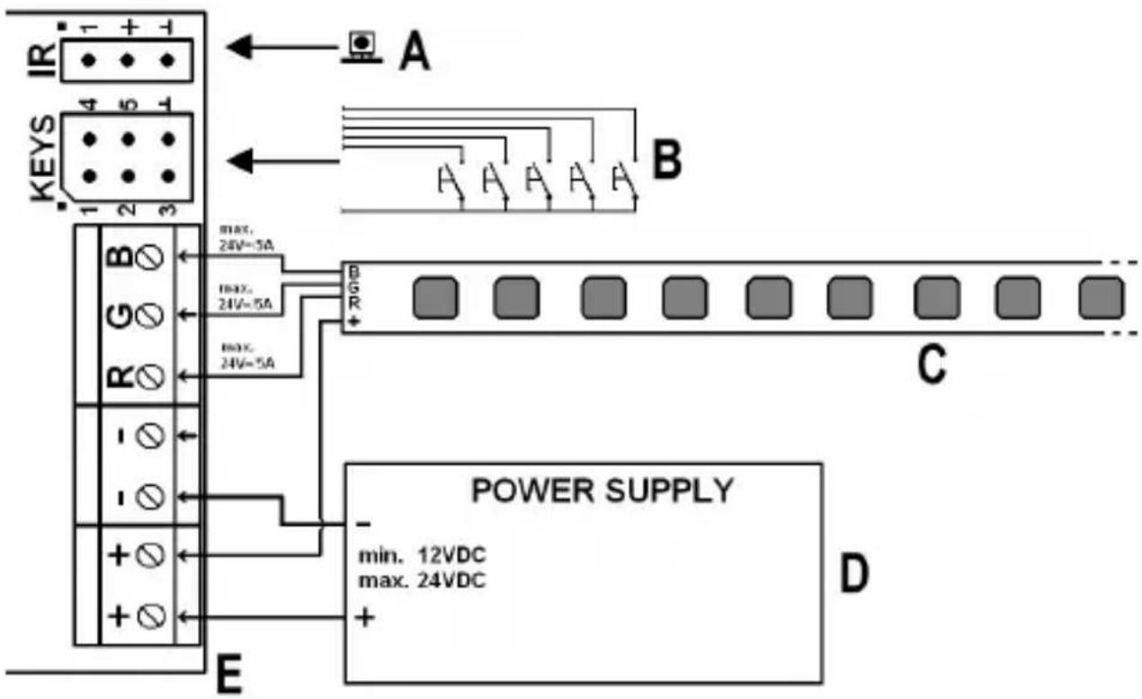
A IR receiver
B External keypad
C LED strip
D External mains power supply plug for the controller and the light strip (the mains power unit must be able to supply sufficient power for three colour channels!).
E Controller
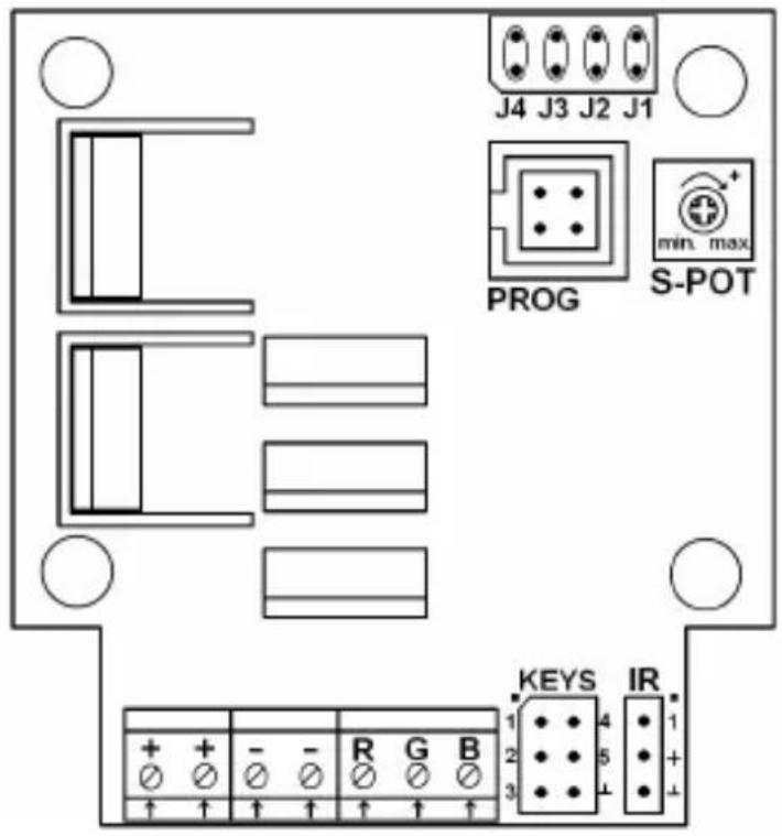
7. Selecting Start Program
First remove the plastic cover by lifting it upwards. To do so, press the individual attachment notches on the edge of the housing slightly inwards so that the cover comes away from the base of the unit.
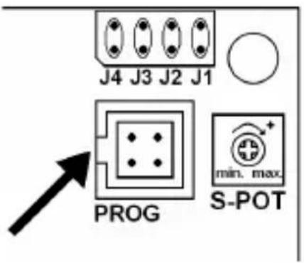
There are 4 jumper bridges on the circuit-board J1, J2, J3 und J4, as shown on the upper right of the adjacent figure.
These jumper bridges allow you to select one of the lighting programmes which will be activated automatically when the power supply is attached.
The speed of the lighting program can be selected with the "S-POT" dial, use a suitable screwdriver to set the dial.
The following levels can be selected:
1 x, 12 x, 14 x, 1/16 x, 1/64 x, 1/128 x base speed (direction.: max. -> min.)
In the following table "x" indicates an attached jumper. A description of the lighting programs is available on the next page.
x - - - Colour change (slow fading)
- x - - Colour change (no hold time)
x x - - Tempest
- - x - Fireplace
x - x - Sunrise and sunset
- x x - Colour flashes
x x x - User program 1
- - - x User program 2
All other jumper combinations activate colour change at normal speed.
Description of the lighting programs:
Colour change (standard): Different colours alternating. Colours are held for 5 seconds, fade time approx. 0.5 seconds.
Colour change (slow fading): As before but hold time is the same as fade time (3 seconds).
Colour change (no hold time): Constant colour change with no hold time.
Tempest: Simulation of a storm and "sheet lightning".
Fireplace: Simulates a fire
Colour flashes: 3x flashes of different colours, pause, etc.
Sunrise and sunset: Slow brightness / colour change to simulate sunrise / sunset.
User programs 1 & 2: Can be created with the PC software and transmitted to the controller using the programming adapter; the device is supplied with two example programs saved to these settings.
The "Tempest" and "Fireplace" settings do not allow you to change speeds.
8. Keypad
a) Keypad connection
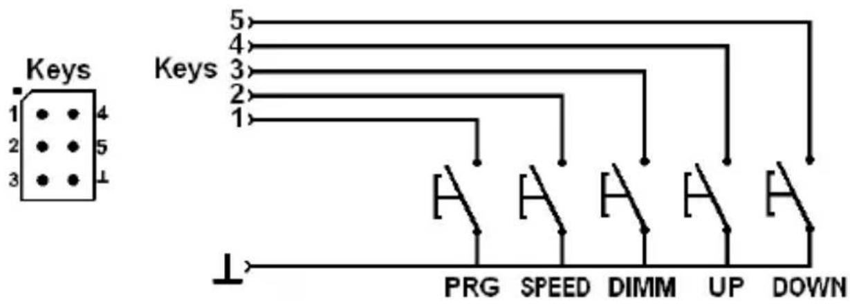
The 6 pins labelled "Keys" (see figure above) allow the attachment of up to 5 external keys which can be used to control the basic functions of the controller.
Pin Button Function
1 PRG Program selection (For a description of the lighting programs see chapter 7)
2 SPEED Speed setting
3 DIMM Brightness setting (additional to the setting of the rotary/dial potentiometer "S-POT")
4 UP Key function "UP"
5 DOWN Key function "DOWN"
6 - Earth connection for all buttons
b) Keypad operation
Select program
Briefly press the "PRG" button. Then you can use the "UP" or "DOWN" buttons to select the lighting programme (see chapter 7).
Setting speed
Briefly press the "SPEED" button. Then you can repeatedly press the "UP" or "DOWN" button to either increase or decrease speed.
Setting the brightness
Briefly press the "DIMM" button. Then you can use the "UP" or "DOWN" buttons to select the desired brightness.
Switching the controller on/off
hold down the "PRG" button for longer than 3 seconds, this switches the controller and the connected LED strip either on or off.
After the unit is switched on, the lighting programme which was selected with the J1 - J4 jumper bridges will start automatically. The speed will depend upon the setting of the "S-POT" dial.
9. IR Remote Control
The RGB-LED controller can also be controlled with a suitable IR remote control. The delivery does not include any IR remote control; it can be ordered separately. Observe the accessories offered on www.conrad.com for the RGB-LED controller on the product website.
To increase the number of compatible remote controls, the RGB-LED controller supports additional device codes as of version 1.3.
We recommend the following IR remote controls for operation:
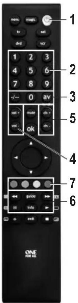
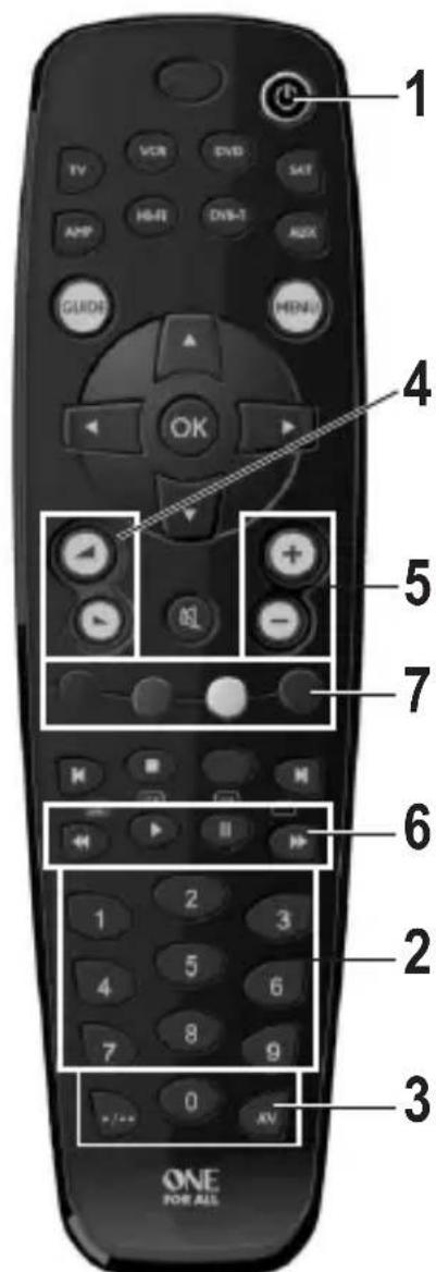
„OneForAll URC 2981“, item no. 943361: „OneForAll URC 3920“, item no. 942168:
Device code 0081 = Philips VCR Device code 20081 = Philips VCR
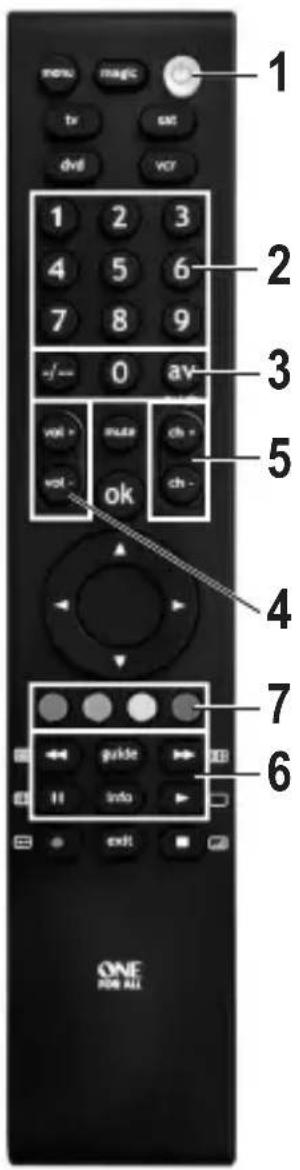
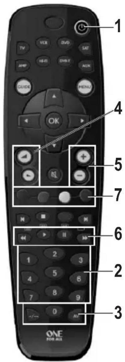
1: ON/OFF
Switch on the control device. The programme set with the jumpers is started. It is executed with the speed pre-selected by potentiometer and at full brightness. Repeated operation switches off the device again.
2: Programme selection buttons „1“ to „9“
Selection and start of the respective colour sequence; start with basic speed and full brightness
Relevant for setting own colours. „AV“ leads to increase, „-/--“ to reduction of the respective colour share when setting own colours, see item 7, bottom.
4: „Volume down“/„Volume up“ (or control cross left/right)
Brightness of the programme played up/down
5: „Ch+“/„Ch-“ (or control cross up/down)
Start of the next or last programme with basic speed and full brightness
6: Forward/reverse/pause/start
Accelerate / decelerate / pause / resume programme
7: Red/green/blue buttons
Mix colour:
Pushing button „AV“ briefly first: Colour ratio is increased.
Pushing button „-/--“ briefly first: Colour ratio is decreased.
A running programme is terminated.
10. Connection and Startup

Connection and installation of the controller may only be carried out if the controller is separated from the power supply.
- Depending on the site of installation, the LED strip and the controller will need to be attached and then connected by cables. Mount the LED strip such that no short circuits can occur and that the LED strip is firmly attached.
When installing the controller you must ensure that it is placed in a well-ventilated area (do not set in insulating material as this will pose a fire risk!). In addition, select a location which is not accessible to children.
Pay attention when inserting the screws that no power, gas or water pipes can be damaged.
Never install the controller or the LED strip on or near to easily inflammable surfaces; also never operate the controller and the LED strip where flammable or explosive gases/dust occurs or close to areas where there is a risk of explosion.
- Ensure that the cables are appropriately dimensioned when connecting the LED strip to the controller and the power supply.
The cable diameter for connecting cables is dependent on the number of LED strips connected. Please keep in mind that the colour for the three colours (R, G, B) is additive, ensure that the cables are dimensioned accordingly! - Connect the LED strips (not included) with one another, make sure that the polarity is correct.
- Then connect the LED strips to the RGB clamps (see Chapter 6) and the positive terminal.

The positive terminal of the LED strip can also be directly connected to the power supply positive lead.
Only LED strips with a common positive terminal (shared anode) may be used; never connect different LED strips to the controller.
When connecting ensure the correct order of colours (R = red, B = blue, G = green).
- The "KEYS" connection field allows 5 buttons to be attached, which can also be used to control the lighting programs, see chapter 8.
-
If you wish, connect the IR receiver with the IR connection on the circuitboard. Via this connection and in connection with the IR remote control, you can control the lighting programmes, see chapter 9.
-
Check all component connections are correct once again.
- Finally, connect the power supply observing the correct polarity with the "+" and "-" terminals on the controller.
The operating voltage must lie between 12 and 24 V/DC.
Depending on the number of LED strips connected, a current supply of up to 15 A is required (the power required for the three colours R, G, B is additive).
- Directly after you connect the power supply, the device starts the lighting program preset with the J1-J4 jumpers (see chapter 7); the speed corresponds to that set with the "S-POT" dial.
The two user programs contain factory preset programs. If you wish to change these programs you will need to use the PC software supplied and the USB programming adapter (Conrad item no. 197339).
11. Driver/Software Installation
→ Minimum operating requirement is Windows XP or Vista/7/8/10. Operation with earlier Windows versions is not possible.
- First install the driver for the USB programming adapter (Conrad item no. 197339). Observe its operating instructions.
- Then insert the CD included in delivery into the appropriate drive of your computer and install the controller software.
You require "Microsoft .NET Framework" to operate the software. This is automatically installed if it is not currently on your computer.
• After the software installation is complete, an icon for the software appears on your desktop. - Now connect the computer to the controller using the USB programming adapter, see chapter 12.
12. Connection to a Computer
Before you connect the controller and computer install the driver software for the USB programming adapter (Conrad item no. 197339) and then the controller software.
- First remove the controller's plastic cover by lifting it upwards. To do so, press the individual attachment notches on the edge of the housing slightly inwards so that the cover comes away from the base of the unit.
- Connect the "PROG" socket on the controller (see figure on the right) to a free USB port on the computer using the programming adapter.
Windows recognises the new hardware when it is connected for the first time and completes the installation of the required drivers.
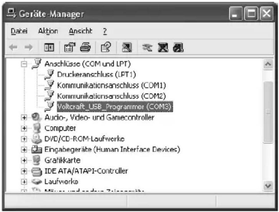
- In the Windows Control Panel (in Device Manager) you can check which COM port has been assigned to the USB programmer (in the figure below it is "COM3"). This COM port should be set after the software starts (see chapter 13), so that the software can make a connection with the controller via the USB programmer.
First install the driver and the software as described in chapter 11. Then connect the controller with a free USB port on your computer, see chapter 12.
Start the software, the following appears (newer versions may appear slightly different):
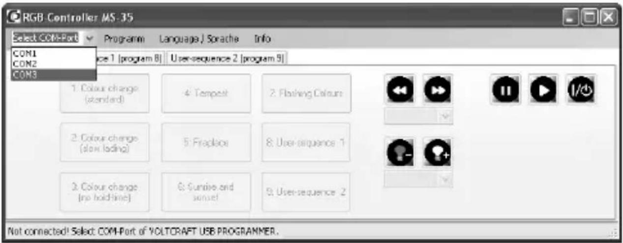
Select the correct COM port for the USB programmer as shown above (see also chapter 12).
Depending on how many COM ports you have in your computer or which name Windows assigns to the COM port, the correct COM ports is COM3 for example.
If no connection can be made to the USB programmer, check whether the COM port of the USB programmer is present in the Control Panel, see chapter 12.
If the USB programmer is found and the RGB controller as well, the bottom line of the window shown above will read "Connected" and the buttons in the window will be activated, see next page.
As confirmation of correct connection between the computer and the controller, a brief colour series appears on the LED strip (red -> green -> blue, approx. every 0.5 seconds).
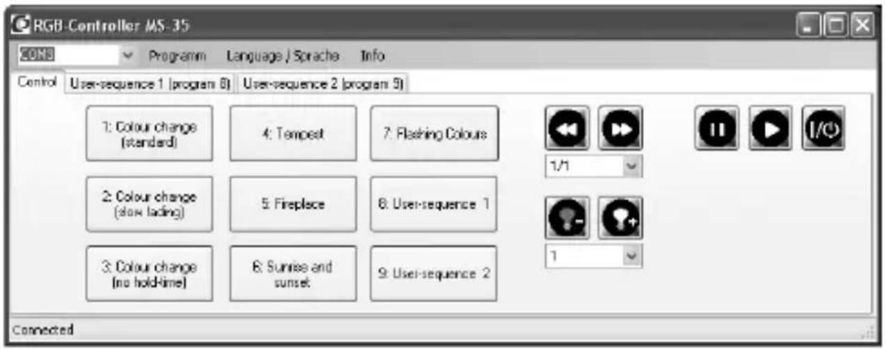
Start one of the pre-programmed lighting programs by clicking it with the mouse. With the symbols in the area on the right you can:
- Changing the brightness
- Change speed
- Stop/start a light program
- Switch the controller on/off
To programme a lighting program yourself, select "User-sequence 1" or "User-sequence 2".
![RGB Controller MS-35 COM3 Programm Language/Sprache Info Control User-sequence 1 [program 8] User-sequence 2 [program 9] 5 Number of colour transitions Load Save Send program R 255 0 0 255 0 G 0 255 0 255 0 B 0 0 255 255 0 hold - time 3 3 3 3 1 cross-lade time 1 1 1 1 1 Edit 1 Edit 2 Edit 3 Edit 4 Edit 5 Connected](/content/2026/04/628963/images/d2b184f5e9b2c98366fa4b61121243ca5a77fddcb1eed09054abb4454e98afec.jpg)
In the upper left of the window you can set the desired number of colour changes (in the figure above 5 colour changes are selected). Every colour change allows the intensity of the basic colours (RGB), the hold time and the cross-fade time.
The light programs you have created can be saved on your computer or reloaded and of course copied to the controller.
The program folder on the hard drive contains several light program examples.
If you click the "Edit" button below the settings area, you can simply changes the settings using slide switches, see the following figure.
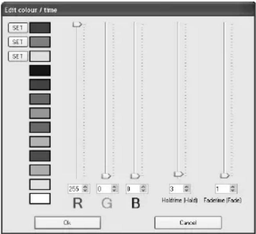
The "0" setting for brightness deactivates the LEDs, the setting "255" results in maximum brightness.
The speed setting "1" corresponds to approx. 0.13 seconds, "255" corresponds to approx. 32 seconds.
The three "SET" buttons allow you to save the three colours for use in other colour changes (set the desired colours using the slide switch and then click the "SET" button to save).
The predefined colours can be easily selected with a simple click.
14. Disposal
Electronic devices are recyclable waste and must not be placed in household waste. Always dispose of the product according to the relevant statutory regulations.
15. Technical Data
Supply voltage....12 - 24 V/DC (depending on the LED strip)
Current consumption without lights .....typ. 25 mA
Supply to LED strip:
Current per colour channel ....max. 5 A
Recommended cable diameter.....at least 1 mm ^2
with supply cable length exceeding 1 m 1.5 mm ^4
Length of cable....max. 2 m
Supply to RGB controller:
Current total....max. 15 A
Recommended cable diameter....min. 2 x 1 mm ^2
with supply cable length >1 m min. 2 x 1.5 mm ^4
Length of cable....max. 5 m
Cable length to IR receiver....max. 2 m
Operating temperature ....0 °C to +65 °C
Ambient air humidity....max. 60%, non-condensing
Degree of protection....IP20
Page
France (email) : technique@conrad-france.fr
apparaatcode 0081 = Philips VCR apparaatcode 20081 = Philips VCR
1: ON/OFF
Copyright 2017 by Conrad Electronic SE.
This is a publication by Conrad Electronic SE, Klaus-Conrad-Str. 1, D-92240 Hirschau (www.conrad.com).
All rights including translation reserved. Reproduction by any method, e.g. photocopy, microfilming, or the capture in electronic data processing systems require the prior written approval by the editor. Reprinting, also in part, is prohibited. This publication represent the technical status at the time of printing.
Copyright 2017 by Conrad Electronic SE.
Copyright 2017 by Conrad Electronic SE.
Copyright 2017 by Conrad Electronic SE.