
AZ4210 - Alarm system ABUS - Free user manual and instructions
Find the device manual for free AZ4210 ABUS in PDF.
| Brand | ABUS |
| Model | AZ4210 |
| Product type | Control element for TERXON L burglar alarm system |
| Dimensions (H x W x D) | 134 mm x 134 mm x 23 mm |
| Weight | 200 g |
| Power supply | 12 V DC |
| Power consumption | 90 mA max. |
| Display | LCD 2 lines of 16 characters |
| Zones | 2 DEOL zones with anti-masking function |
| Outputs | 1 transistor output, negative switching, 100 mA max. |
| Operating temperature range | -10 °C to 55 °C |
| Maximum humidity | 96 % |
| Main functions | Activation/deactivation by key cards (low frequency, range 120 mm), system status and alarm display, zone management, built-in speaker volume adjustment |
| Maintenance and cleaning | Clean with a soft, dry cloth. Do not use abrasive products or solvents. |
| Safety | Professional installation recommended. Disconnect power before any intervention. |
| Spare parts and repairability | Spare parts available on request. Repair by an authorized center. |
| General information | Designed for the TERXON L alarm system. Compatible with 8-zone wired extensions. Supplied with mounting base. |
Frequently Asked Questions - AZ4210 ABUS
User questions about AZ4210 ABUS
0 question about this device. Answer the ones you know or ask your own.
Ask a new question about this device
Download the instructions for your Alarm system in PDF format for free! Find your manual AZ4210 - ABUS and take your electronic device back in hand. On this page are published all the documents necessary for the use of your device. AZ4210 by ABUS.
USER MANUAL AZ4210 ABUS
natural_image
Front view of a white electronic device with a green screen and control buttons (no visible text or symbols)LCD control panel Installation Instructions (UK) 7
© Security-Center GmbH & Co. KG, ABUS Group, April 2008
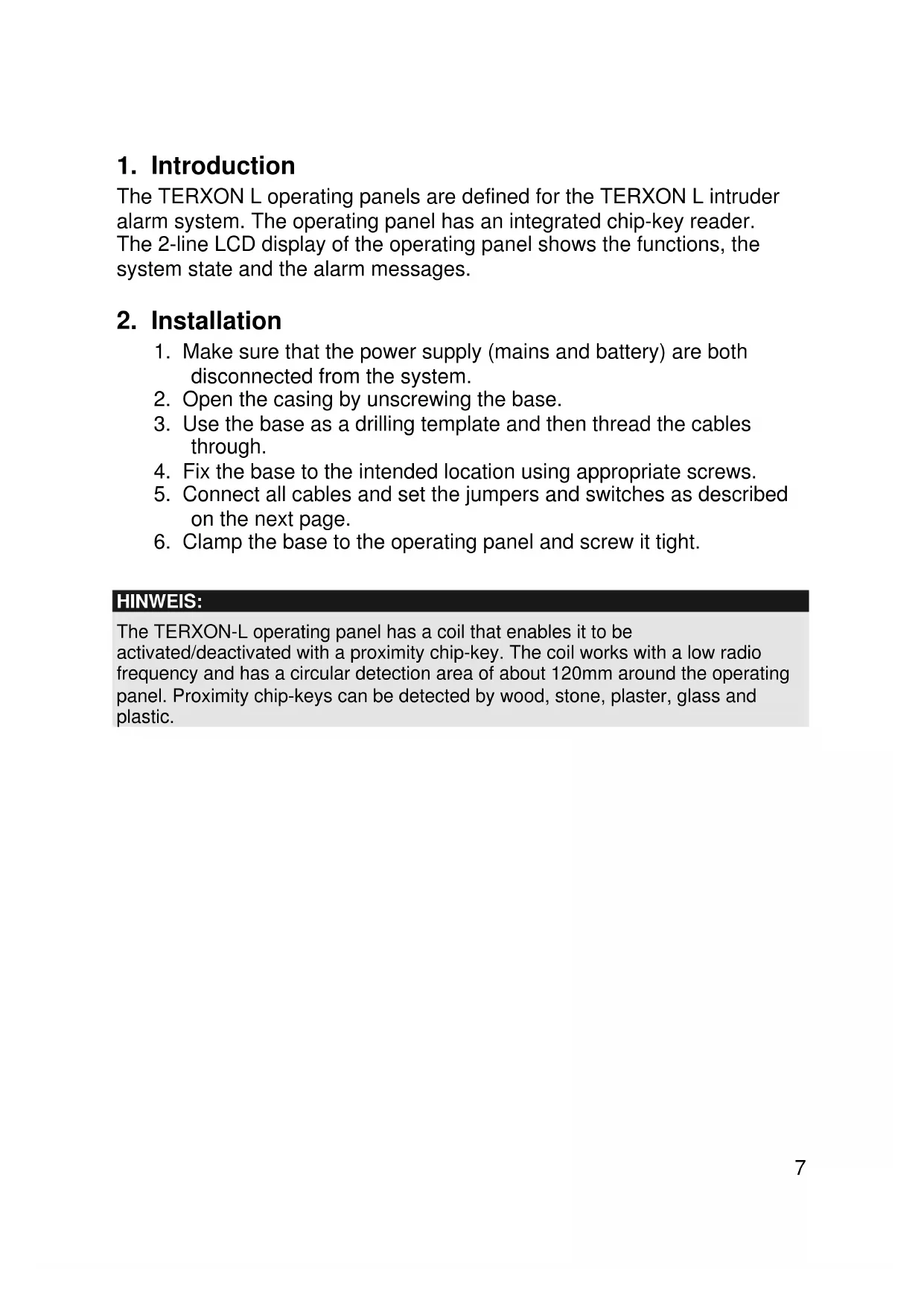
1. Introduction
The TERXON L operating panels are defined for the TERXON L intruder alarm system. The operating panel has an integrated chip-key reader. The 2-line LCD display of the operating panel shows the functions, the system state and the alarm messages.
2. Installation
- Make sure that the power supply (mains and battery) are both disconnected from the system.
- Open the casing by unscrewing the base.
- Use the base as a drilling template and then thread the cables through.
- Fix the base to the intended location using appropriate screws.
- Connect all cables and set the jumpers and switches as described on the next page.
- Clamp the base to the operating panel and screw it tight.
HINWEIS:
The TERXON-L operating panel has a coil that enables it to be activated/deactivated with a proximity chip-key. The coil works with a low radio frequency and has a circular detection area of about 120mm around the operating panel. Proximity chip-keys can be detected by wood, stone, plaster, glass and plastic.
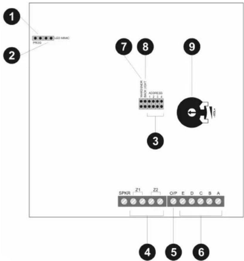
3. Components and Wiring
flowchart
graph TD
    A["PROG"] --> B["LED MMMC"]
    C["3"] --> D["SPKR Z1 Z2 Q/P E D C B A"]
    E["7"] --> F["ADDRESS 1 2 3 4"]
    G["9"] --> H["e VOL*"]
    I["4"] --> J["5"]
    K["6"] --> L["6"]
1.) PROG
As a factory default, the PROG jumper is plugged off. When the jumper is placed, an extended BUS protocol will be transmitted to the panel.
Note:
The mains power LED lights up when 12V is connected. A main fault is shown as an alarm on the operating panel.
2.) LED MIMIC
If this jumper is connected, the red LED of the operating panel lights up when the output is switched. As a factory default, the output is set to "Pending", where the LED lights up if there are two alarm messages.
Remove the jumper if the LED is not to be used.
3.) ADDRESS
Change the address of the operating panels to 1, 2, 3 or 4 by connecting the individual jumpers. If you do not connect the jumper, this defines address 5. The number of operating panels depends on the type of wiring and the network number. For further information, see the installation instructions.
An address can only be defined once. After changing an address, the voltage supply must be reconnected.
4.) Zone wiring (optional)
The operating panel supports the DEOL (FSL) wiring of two zones. Connecting sensor with and without masking is possible. For wiring hints, please see the installation instructions of the alarm centre.
The contacts of the sensors are usually NC (normally closed); if you want NO (normally open), you have to invert the corresponding zones.
Note: If the operating panel is connected to an 8-zone wired extension, the zones cannot be used.
Note: If the sensor's voltage supply is to flow via the operating panel, two extra leads are needed for the connections to connectors A (+12V DC) and B (0V) (see Installation Instructions).
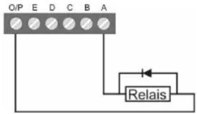
5.) Connecting the outputs (optional)
In the factory setting, the O/P (transistor) is connected to 12V DC and switches to 0V if the output is activated. This output can be inverted during programming if necessary.
flowchart
graph TD
    A["O/P"] --> B["Relais"]
    C["E"] --> B
    D["D"] --> B
    E["C"] --> B
    F["B"] --> B
    G["A"] --> B
    B --> H["Output"]
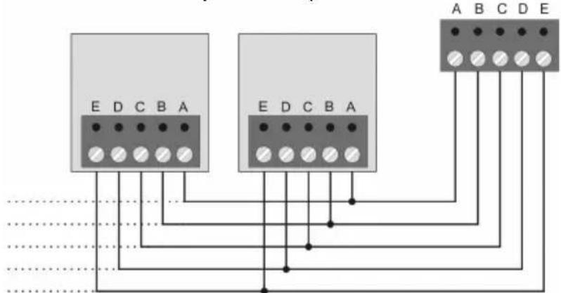
6.) Wiring to panel/extension
Normally an 8 x 0.22 mm ^4 alarm cable is used. Use screened cables in areas with interference frequencies (see Installation Instructions).
7.) WARD SNDR
If the output of the operating panel is programmed as type "Sndr Ctl" and the jumper is connected, the loudspeaker sounds for selected partitions only. For further information, see the Installation Instructions.
8.) BACK LIGHT
Without jumper (default) – The lighting of the display and the number keys is switched off. If a key is pressed, the lighting switches on at full strength for 5 seconds.
9.) Volume adjustment
Use this potentiometer to adjust the volume of the internal signalling device and the connected loudspeakers.
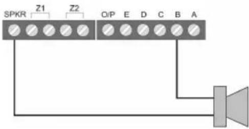
Connecting loudspeakers (optional)
External 16 Ohm loudspeakers (in series with internal loudspeaker).
4. Technical Data
| Power consumption | 90mA max. at 12V DC |
| Display 2 lines each | with 16 characters |
| Zones 2 Zones, DEOL with anti-masking | |
| Outputs 1 output negatively switching,100mA max. | |
| Dimensions 134mm x 134mm x 23mm (HxWxD) | |
| Weight 200g | |
| Ambient operating temperature | -10° to 55°C |
| Ambient operating humidity | Max. 96% |
© Security-Center GmbH & Co. KG, ABUS Group, April 2008
1. Introduction
© Security-Center GmbH & Co. KG, ABUS Group, april 2008
© Security-Center GmbH & Co. KG, ABUS Group, april 2008
1. Caratteristiche
© Security-Center GmbH & Co. KG, ABUS Group, Aprile 2008


- Introduction
- Installation
- HINWEIS:
- Components and Wiring
- 1.) PROG
- Note:
- 2.) LED MIMIC
- 3.) ADDRESS
- 4.) Zone wiring (optional)
- 5.) Connecting the outputs (optional)
- 6.) Wiring to panel/extension
- 7.) WARD SNDR
- 8.) BACK LIGHT
- 9.) Volume adjustment
- Connecting loudspeakers (optional)
- Technical Data
- Caratteristiche
Brand : ABUS
Model : AZ4210
Category : Alarm system