
FUMK50031B - Alarm system ABUS - Free user manual and instructions
Find the device manual for free FUMK50031B ABUS in PDF.

| Product type | Narrow Secvest wireless opening detector |
| Reference | FUMK50031 |
| Compatible equipment | Secvest control panels FUAA50000, Secvest Touch FUAA50500, FUAA10000, FU8000, FU5000 |
| Sensor dimensions (H x W x D) | 19 x 103 x 24 mm |
| Magnet dimensions (H x W x D) | 12 x 55 x 12 mm |
| Sensor weight (with battery) | 40 g |
| Magnet weight | 10 g |
| Power supply | 1 CR2 3 V lithium battery (LiMnO2) |
| Replacement battery | FU2990 |
| Battery life | Typically > 2 years |
| Detection method | Reed contact (magnetic field sensor) |
| Wireless range | Up to 500 m in open field, approx. 30 m indoors |
| Operating frequency | 868.6625 MHz (low data rate) |
| Tamper monitoring | Yes (cover and wall contact) |
| Security grade | 2 (EN 50131-1) |
| Protection rating | IP34 (indoor, mounted) |
| Operating temperature | -10 °C to +55 °C |
| Max. relative humidity | 75 % non-condensing |
| Housing material | PC/ABS |
| Power consumption | Standby current 3 μA, max. 35 mA |
| Voltage monitoring | Undervoltage threshold 2.4 V, fault signal transmitted to the control panel |
| Maintenance | Clean if necessary, replace batteries every 2 years or upon warning |
| Installation | Reserved for qualified technical personnel, commissioning in Installer mode |
| Warranty | 2 years, covers material and manufacturing defects |
Frequently Asked Questions - FUMK50031B ABUS
User questions about FUMK50031B ABUS
0 question about this device. Answer the ones you know or ask your own.
Ask a new question about this device
Download the instructions for your Alarm system in PDF format for free! Find your manual FUMK50031B - ABUS and take your electronic device back in hand. On this page are published all the documents necessary for the use of your device. FUMK50031B by ABUS.
USER MANUAL FUMK50031B ABUS
natural_image
Simple line drawing of a mobile phone with a screen and an attached rounded rectangle (no text or symbols)DE
Installation instructions and user manual
FR
Magnet:
natural_image
Simple line drawing of a door panel and a vertical bar (no text or symbols)natural_image
3D diagram of three rectangular blocks with X, Y, Z coordinate axes labeled (no text or symbols beyond axis labels)Montage
natural_image
Diagram showing two views of a door handle with arrows indicating movement, no text or symbols presentPlastikteil nicht ausbrechen / Do not break plastic part / niet breken kunststofdeel / pas rompre pièce en matière plastique / ikke bryde plastdel / No romper la pieza de plástico / nie złamać część plastikową / inte bryta plastdel / Non rompere parte plastica
natural_image
Diagram of a vertical cylindrical device with internal components and a screw, no visible text or symbolsLED aktivieren
natural_image
Simple line drawing of a mobile phone with a screen and an app icon (no text or symbols)DE
Installation instructions and user manual
FR
Information on user manual
Dear Customer,
Thank you for purchasing this product. This device is a product that has been built using state-of-the-art technology.
These instructions contain important installation and operation information. Follow the directions and instructions in this user manual to ensure safe operation. Store this manual in a safe place for future reference. This manual constitutes part of the device. If you pass the device on to third parties, please remember to include this manual.
The information, recommendations, descriptions and safety information in this document are based on the experiences and judgement of the ABUS Security-Center GmbH & Co. KG ('ABUS') and may not cover all eventualities. Further information can be obtained from the sales and support staff of ABUS.
Intended use
Only use the device for the purpose for which it was built and designed. Any other use is considered unintended. This product complies with current European and national regulations.
Conformity has been proven, and all related certifications are available from the manufacturer on request.
To ensure this condition is maintained and that safe operation is guaranteed, it is your obligation as user to observe this user manual. If you have any questions, please contact your specialist dealer. Further general information and information on product support can be found at www.abus.com on the general page or for dealers and installers, in the Partner portal.

Note
Please observe the notes and instructions in this user manual! If you do not follow these instructions, any guarantee claim is invalidated. No liability can be accepted for resulting damage.
No part of the product may be changed or modified in any way.
Please observe the local legal requirements. Please consult your local authorities on this.

Danger
This product may only be installed and maintained by qualified staff.
Set the alarm panel to installer mode before starting any installation or maintenance work. Installer mode prevents alarms from being activated when the repeater's cover is opened.
Limitation of liability
Everything possible has been done to ensure that the content of these instructions is correct. However, neither the author nor ABUS Security-Center GmbH & Co. KG can be held liable for loss or damage caused by incorrect or improper installation and operation or failure to observe the safety instructions and warnings. No liability can be accepted for resulting damage. No part of the product may be changed or modified in any way. If you do not follow these instructions, your warranty claim becomes invalid. Subject to technical modifications.
© ABUS Security-Center GmbH & Co. KG, 11/2017
Safety information
Explanation of symbols
The following symbols are used in this manual and on the device:
| Symbol | Signal word | Meaning | |
 | Danger | Indicates a risk of injury or health hazards. | |
 | Danger | Indicates a risk of injury or health hazards caused by electrical voltage. | |
 | Important | Indicates possible damage to the device/accessories. | |
 | Note | Indicates important information. | |
 | The EU Directive WEEE 2012/19/EU governs the proper recovery, treatment and recycling of used electronic devices. This symbol means that, in the interest of environmental protection, the device must be disposed of separately from household or industrial waste at the end of its lifespan in accordance with applicable local legal guidelines. Used devices can be disposed of at official recycling centres in your country. Obey local regulations when disposing of material. Further details on returns (also for non-EU countries) can be obtained from your local authority. Separate collection and recycling conserve natural resources and ensure that all the provisions for protecting health and the environment are observed when recycling the product. | ||
Packaging

Danger
Keep packaging material and small parts away from children. There is a risk of suffocation!
Remove all packaging material before using the device.
Information on the battery

Danger

Danger
The device is supplied with direct current from a battery. To guarantee a long lifespan and avoid fire and injury, please note the following:
- Do not dispose of the battery with household waste.
- The battery must not be directly exposed to heat or sunlight, and must not be stored in hot places.
- The battery must not be burned.
- The battery must not come into contact with water.
- The battery must not be dismantled, pierced or otherwise damaged.
- The battery contacts must not be short-circuited.
- The battery must be kept out of reach of from small children.
- The battery cannot be recharged.
Scope of delivery
• 1x Secvest Small Wireless Magnetic Contact
• 1x battery type CR2, lithium
- 2x spacers for magnet
- 2x spacers for detector
- 1x screw with raised head for attaching the upper part of the sensor
- 4x screws with raised head for installation
- 1x manual
Technical data
| Product name | Secvest Small Wireless Magnetic Contact |
| Item number | FUMK50031 |
| Compatible equipment | 868 MHz narrow band receiver from ABUS |
| Environmental class | II (EN 50131-1 + A1:2009 Section 7) |
| Protection class, IP protection class | IP34 (internal spaces, in its installed state)IP = international protection or ingress protection3 = tools and wires4 = splashing water |
| Operating temperature | -10°C to +55°C |
| Humidity, maximum | Non-condensing average relative humidity 75% |
| Housing material | PC/ABS |
| Dimensions – sensor | 19 x 103 x 24 mm (WxHxD) |
| Dimensions – magnet | 12 x 55 x 12 mm (WxHxD) |
| Weight – sensor | 40 g (with battery)30 g without battery, 10 g battery only |
| Weight – Magnet | 10 g |
| Security level | 2 (EN 50131-1 + A1:2009 Section 6) |
| Tamper monitoring | yes |
| Tamper protection | according to EN50131-2-6 Section 4.5 |
| Displays | 1 LEDtrigger signalling, for infrared programming |
| Connections | Jumper to deactivate the front LEDPlug-in terminal |
| Type of power supply | Type C (EN 50131-1 Section 9 and EN 50131-6 Section 4.1)Power supply compliant with EN50131-1:2006+A1:2009 9.2 and EN50131-6 if installed correctly together with Secvest FUAA50xxx. |
| Power consumption/energy consumption | 3 μA standby current35 mA max. |
| Operating voltage | 3 V DC |
| Battery type | 1x CR2 battery, 3V, lithium LiMn02Replacement battery FU2990 |
| Battery life | Typically >2 years |
| Battery under voltage threshold | 2.4 V, ‘Flat battery’ fault at < 2.4 V |
| Voltage monitoring | During operation the voltage provided by the battery is monitored. If the voltage is below the lower threshold of 2.4 V, a fault report is sent to the alarm control panel and the user is informed. |
| Operating frequency, wireless | 868.6625 MHz narrow band |
| Transmission power, wireless | max. 10 mW |
| Range, wireless | max. 500 m range outdoors approx. 30 m indoors (depending on building structure) |
| Type of detection | Reed contact as sensor for magnetic field |
| Standards for intrusion and panic button devices | Intrusion Standard: EN 50131-2-6; Certification body: Telefication |
| Conformity | Third-party verification of compliance was carried out by Telefication. |
| EU Directives | RED: 2014/53/EU EMC: 2014/30/EU RoHS: 2011/65/EU WEEE: 2012/19/EU ErP: 2009/125/EU Low Voltage: 2014/35/EU General Safety: 2001/95/EC |
| General | This product must be installed by a qualified service engineer. |
Functional principle and features
General
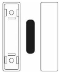
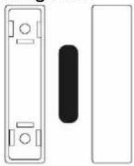
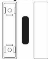
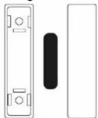
The FUMK50031 is a wireless magnetic contact for doors and windows. It was designed to operate together with 868 MHz narrow band receivers from ABUS. The FUMK50031 consists of two components: the sensor (usually installed on the door frame or window frame) and the magnet. If the door or the window is opened, the two components are separated. This information is then transmitted to the respective alarm panel or receiver component. This triggers a corresponding alarm.
Main features
- Narrow design for particularly small installation proportions
- Reliably detects opening of windows and doors.
- Magnet can be mounted on the right or the left
- Wide range
-
Impact-resistant construction
-
Tamper monitoring
• Cover and wall tamper contact - Simple installation
- Supervision
- Monitors voltage
Compatible equipment
The Secvest Small Wireless Magnetic Contact FUMK50031 is compatible with:
Alarm panels
Components
- Secvest FUAA50000, Secvest Touch FUAA50500, Secvest FUAA10000, FU8000, FU5000
• Repeater module FUMO50010
• Universal module UVM FUMO50020
- Wireless extensions Terxon MX AZ4120 and LX AZ4220
Device description
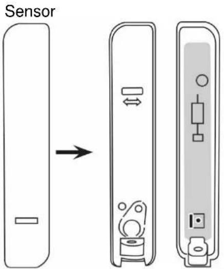
Magnet:
natural_image
Simple line drawing of a door panel and a vertical bar (no text or symbols)Approximation and separation distances on ferromagnetic and non-ferromagnetic mounting surfaces due to EN 50131-2-6, chapter 5.2 c)

Danger

Note
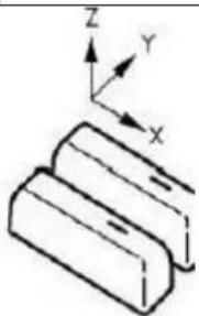
This table shows the relevant distances required between the sensor and the magnet for arming/disarming the alarm.
Only the movement within the specified axis is accepted, where sensor and magnet are optimally positioned on the other two axes.
| Interface | Status | Distance (mm) | ||
| X | Y | Z | ||
| Fe | 22 | 14 | 32 | |
| 17 | 11 | 26 | ||
| Fe | 15 | 14 | 19 | |
| 11 | 10 | 10 | ||
natural_image
3D diagram of stacked rectangular blocks with X, Y, Z axis indicators (no text or symbols)Installation
Step 1: Select installation location for the detector
Select an installation location which:
- is within the wireless range of the alarm panel or the wireless-receiver (max. 500 m outdoors).

Note
The wireless signal strength of the detector should be tested at the installation location of the alarm panel prior to installation.
The wireless range can be shortened when the sensor is mounted on or near a metal surface.

Note
The detector must not be installed in the following locations:
- at a distance of less than 1 m from household electrical systems or power distributors
• inside metal housings - close to high-voltage devices or electronic devices such as computers, photocopiers or other wireless devices.
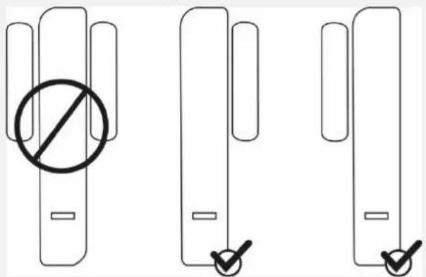
The sensor should be mounted at the top, preferably on the stationary part of the door or window frame. This ensures consistent transmission power during operation.
The spacers that are included within the scope of delivery can be mounted behind the magnet or the sensor. The detector must not be installed on the hinge-side.
Sensor and magnet can also be positioned opposite each other, as long as:
- the arrows on the back plates of sensor and magnet are aligned with each other
- the maximum distance between the front covers does not exceed 10 mm when mounted on a metal surface or 15 mm when mounted on a non-metallic surface.

Note
The magnet can be mounted on the right or the left side of the sensor.
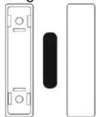
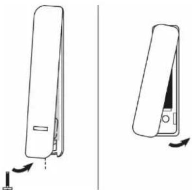
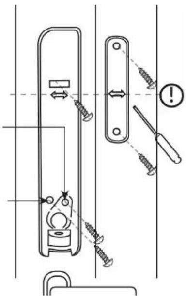
Step 2: Open the cover of sensor and magnet
- Remove the screw from the underside of the sensor and open the cover.
- Use a suitable slotted screwdriver and open the cover of the magnet.
natural_image
Diagram showing two views of a device with arrows indicating motion, no text or symbols presentStep 3: Install detector on door or window

Note
A moulded part in the recess of the back plate serves as an anti-removal wall contact. This moulded part must be affixed to the wall with a screw. If this is not done, tamper detection for removal from the wall is deactivated.

Danger
When installed without an anti-removal wall contact, the detector can be ripped off without a tamper alarm being triggered.
The detector also loses its certification for security level 2 as a result.
To prevent this, the tamper mechanism must be affixed to the wall, and will break off at the defined predetermined breaking points in the event of a tamper attempt, triggering a tamper alarm.
Do not break off the plastic part.
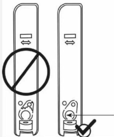
Plastikteil nicht ausbrechen / Do not break plastic part / niet breken kunststofdeel / pas rompre pièce en matière plastique / ikke bryde plastdel / No romper la pieza de plástico / nie złamać część plastikową / inte bryta plastdel / Non rompere parte plastica
- Place the sensor and the magnet on the door or window and align both vertically. Mark the mounting points.

Note
Ensure that the reed contact and the magnet are at roughly the same height. There are arrows on the inside of the rear panel of the sensor housing and the magnet housing as an aid.
- Drill holes to fit the diameters of the screws.
- Insert the supplied screws through the mounting holes of the sensor and the magnet. Insert the screws. Do not tighten the screws yet.
- Realign the sensor and the magnet vertically. Now tighten the screws.
Mit Sabotage / With tamper / Met sabotage / Avec le sabotage/ Med sabotage / De Sabotaje / Z sabotażowego / Med sabotage / Con Sabotaggio
Ohne Sabotage / Without tamper / Zonder Sabotage / Sans sabotage / Uden sabotage / Sin Sabotaje / Bez sabotażowego / Utan Sabotage / Senza Sabotaggio
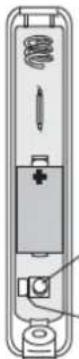
Step 4: Power supply
- Insert the batteries into the bracket, ensuring the polarity is correct.
Step 5: Program detector into alarm panel or receiver component

Note
The following describes direct programming on the Secvest alarm panel FUAA50000. For web-based programming and programming to other receivers, please read the relevant chapter in the instructions about these components.
- If this has not been done already, switch the alarm panel on.
- Select:
Installer mode -> Components -> Detector -> Wireless zones -> Add/Remove detector - Choose a free wireless zone. The message 'Activate the tamper contact of the detector' is displayed.
- Flick the tampering switch.
The detector will then send a pairing signal to the alarm panel. The alarm panel will recognise the detector. - Once the pairing signal has been received by the wireless alarm system, it will emit two beeps. The message ‘Detector was programmed to: zone 2xy’ and the incoming signal strength are displayed.
- Confirm the successfully completed pairing on the control panel.
Step 6: Test the system
- Test the system fully.
Signal strength
Installer mode > Test > Signal strengths > Detector
After selecting the signal strengths for all detectors is displayed on the alarm panel. For more details, please refer to the relevant instructions for the alarm panel or wireless extension.
Walk test
Installer mode > Test > Walk test
After making the selection, you can choose whether to test all detectors in the system, in a partition of the system, or individual detectors. For more details, please refer to the relevant instructions for the alarm panel or wireless extension.
- Flick the tampering switch. The message 'S' for tamper is displayed.
- Open the door or the window. The message 'A' for alarm is displayed.
Step 7: Close the cover of the sensor and the magnet
- Close the sensor cover and re-tighten the screw on the underside of the sensor.
- Close the magnet cover. The upper part of the magnet cover must be clicked into place on the bottom part.
Step 8: Programming the alarm panel
- Adjust zone type and attributes according to the requirements.
- Exit installer mode on the alarm panel. The system is now ready.
Functions and displays
Operation of the LEDs

Note
Remove the jumper to disarm the front LED.
Enable LED
- to enable programming via infrared. Some products are programmed via infrared (not via wireless).
• to check detector function on site.
Disable LED
• to increase security
• to extend battery life.
Error and tamper monitoring
The detector continually monitors error and tamper states and reports all events to the alarm panel. The following is monitored:
- Tamper contact: The detector's tamper contact is continually monitored.
- Battery voltage: The detector monitors the battery voltage and reports faults to the alarm panel.
- Supervision: The detector continually sends Supervision messages to the alarm panel.
•
Maintenance

Danger
Before opening the sensor cover, make sure that the alarm panel is in installer mode. This prevents the tamper alarm from being triggered.
Test during routine maintenance that the detector works properly.
Check the tamper contact.
Check the functionality of the detector by opening and closing the door or the window.
Clean the detector as required.
Replace the batteries every two years or if the alarm panel displays the message 'Flat battery in detector'. You can find the battery type to be used as a replacement under Technical data.

Note
After removing the old battery, wait 30 seconds before inserting the new battery.
How to replace the batteries:
- Set the alarm panel to installer mode.
- Remove the screw from sensor cover and open the cover.
- Remove the battery.
- Wait 30 seconds and then insert the new battery.
- Close the cover, tighten the cover fixing screws.
- Test the system.
Warranty

Note
- ABUS products are designed and manufactured with the greatest care and tested according to the applicable regulations.
- The warranty only covers defects caused by material or manufacturing errors at the time of sale. If there are demonstrable material or manufacturing errors, the module will be repaired or replaced at the guarantor's discretion.
- In such cases, the warranty ends when the original warranty period of two years expires. All further claims are expressly rejected.
- ABUS will not be held liable for defects and damage caused by external influences (e.g. transport, use of force, operating errors), inappropriate use, normal wear and tear, or failure to observe the instructions in this manual.
- In the event of a warranty claim, the original proof of purchase with the date of purchase and a short written description of the problem must be supplied with the product.
- Should you discover a defect on your detector that was already present at the time of purchase, please contact your dealer directly within the first two years.
Disposal

Dispose of the device in accordance with EU Directive 2012/19/EU – WEEE (Waste Electrical and Electronic Equipment). If you have any questions, please contact the municipal authority responsible for disposal. You can get information on collection points for waste equipment from your local authority, from local waste disposal companies or your dealer,
for example.
Declaration of conformity
ABUS Security-Center hereby declares that the wireless system type FUMK50031 complies with RED Directive 2014/53/EU. The full EU Declaration of Conformity text can be found at:
www.abus.com > Item search > FUMK50031 > Downloads
The Declaration of Conformity can also be obtained from the following address:
natural_image
Simple line drawing of a rectangular device with a small rectangular element on the left side (no text or symbols)| DE | Secvest Schmaler Funk-Öffnungsmelder Installations- und Bedienungsanleitung |
| EN | Secvest Small Wireless Magnetic Contact Installation instructions and user manual |
| FR | Détecteur d'ouverture sans fil Secvest étroit Instructions d'installation et d'utilisation |
| NL | Secvest Smal Draadloos Magneetcontact Installatie- en gebruikershandleiding |
| DK | Secvest Smal Trådløs Åbningsføler Installations- og betjeningsvejledning |
| IT | Secvest Radiorilevatore di Apertura Sottile Istruzioni per l'installazione e per l'uso |
| CE | BOM 12954975 | Version 1.0 |
Introduction
Aimant :
natural_image
Pure electrical circuit lines without any symbolsnatural_image
3D diagram of stacked rectangular blocks with X, Y, Z axis indicators (no text or symbols)Montage
natural_image
Diagram showing two views of a device with arrows indicating motion, no text or symbols presentPlastikteil nicht ausbrechen / Do not break plastic part / niet breken kunststofdeel / pas rompre pièce en matière plastique / ikke bryde plastdel / No romper la pieza de plástico / nie złamać część plastikową / inte bryta plastdel / Non rompere parte plastica
natural_image
Simple line drawing of a rectangular object with a small rectangular cutout and a horizontal bar at the bottom (no text or symbols)| DE | Secvest Schmaler Funk-Öffnungsmelder Installations- und Bedienungsanleitung |
| EN | Secvest Small Wireless Magnetic Contact Installation instructions and user manual |
| FR | Détecteur d'ouverture sans fil Secvest étroit Instructions d'installation et d'utilisation |
| NL | Secvest Smal Draadloos Magneetcontact Installatie- en gebruikershandleiding |
| DK | Secvest Smal Trådløs Åbningsføler Installations- og betjeningsvejledning |
| IT | Secvest Radiorilevatore di Apertura Sottile Istruzioni per l'installazione e per l'uso |
| CE | BOM 12954975 | Versie 1.0 |
Inleiding
Magneet:
natural_image
Pure electrical circuit lines without any symbolsnatural_image
3D diagram of stacked rectangular blocks with X, Y, Z axis indicators (no text or symbols)Montage
natural_image
Diagram showing two views of a device with arrows indicating motion, no text or symbols presentPlastikteil nicht ausbrechen / Do not break plastic part / niet breken kunststofdeel / pas rompre pièce en matière plastique / ikke bryde plastdel / No romper la pieza de plástico / nie złamać część plastikową / inte bryta plastdel / Non rompere parte plastica
Stap 4: Voeding
natural_image
Simple line drawing of a smartphone with a button and rounded body (no text or symbols)DE
Installation instructions and user manual
FR
Magnet:
natural_image
Pure electrical circuit lines without any symbolsnatural_image
3D diagram of three rectangular blocks with X, Y, Z axis indicators (no text or symbols)Montering
Trin 2: Åbn dækslet på sensoren og magneten
natural_image
Diagram showing two views of a device with arrows indicating movement or change, no text or symbols present.natural_image
Simple line drawing of a rectangular object with a small rectangular cutout and a horizontal bar at the bottom (no text or symbols)| DE | Secvest Schmaler Funk-Öffnungsmelder Installations- und Bedienungsanleitung |
| EN | Secvest Small Wireless Magnetic Contact Installation instructions and user manual |
| FR | Détecteur d'ouverture sans fil Secvest étroit Instructions d'installation et d'utilisation |
| NL | Secvest Smal Draadloos Magneetcontact Installatie- en gebruikershandleiding |
| DK | Secvest Smal Trådløs Åbningsføler Installations- og betjeningsvejledning |
| IT | Secvest Radiorilevatore di Apertura Sottile Istruzioni per l'installazione e per l'uso |
| CE | BOM 12954975 | Version 1.0 |
Introduzione
natural_image
Diagram showing three stages of a device or component assembly: before, after, and after (no text or symbols present)Magnete:
natural_image
Pure electrical circuit lines without any symbolsnatural_image
Diagram showing two views of a device with arrows indicating motion, no text or symbols presentPlastikteil nicht ausbrechen / Do not break plastic part / niet breken kunststofdeel / pas rompre pièce en matière plastique / ikke bryde plastdel / No romper la pieza de plástico / nie złamać część plastikową / inte bryta plastdel / Non rompere parte plastica


- Montage
- LED aktivieren
- Information on user manual
- Intended use
- Limitation of liability
- Safety information
- Explanation of symbols
- Packaging
- Information on the battery
- Scope of delivery
- Functional principle and features
- General
- Main features
- Compatible equipment
- Installation
- Step 1: Select installation location for the detector
- Step 2: Open the cover of sensor and magnet
- Step 3: Install detector on door or window
- Step 4: Power supply
- Step 5: Program detector into alarm panel or receiver component
- Note
- Step 6: Test the system
- Step 7: Close the cover of the sensor and the magnet
- Step 8: Programming the alarm panel
- Functions and displays
- Operation of the LEDs
- Error and tamper monitoring
- Maintenance
- Warranty
- Disposal
- Declaration of conformity
- Introduction
- Inleiding
- Stap 4: Voeding
- Montering
- Trin 2: Åbn dækslet på sensoren og magneten
- Introduzione
Brand : ABUS
Model : FUMK50031B
Category : Alarm system