TCS15264ANWH - Speaker Turbosound - Free user manual and instructions
Find the device manual for free TCS15264ANWH Turbosound in PDF.
User questions about TCS15264ANWH Turbosound
0 question about this device. Answer the ones you know or ask your own.
Ask a new question about this device
Download the instructions for your Speaker in PDF format for free! Find your manual TCS15264ANWH - Turbosound and take your electronic device back in hand. On this page are published all the documents necessary for the use of your device. TCS15264ANWH by Turbosound.
USER MANUAL TCS15264ANWH Turbosound
Arrayable 2,500 Watt 2 Way Full Range Loudspeakers with Dendritic Waveguides
6,000 Watt and Arrayable 3,000 Watt Subwoofer
Klark Teknik DSP Technology and ULTRANET Networking
2TC-ANSEFSCOcStGuie3
EN Important Safety Instructions

Terminals marked with this symbol carry electrical current of sufficient magnitude to constitute risk of electronic shock. The only high quality professional speaker cables with 8^ T'smout, locking plugs are installed. All other installation or modification should be performed only by qualified personnel.
This symbol, wherever it appears, shorts you to the presence of uninsulated dangerous voltage inside the enclosure - voltage that may be sufficient to constitute a risk of shock.
This symbol, wherever it appears, stries you to important operating and maintenance instructions in the accompanying literature. Please read the manual.
Caution To reduce the risk of electric shock, do not remove the top cover (or the wear section). No user serviceable parts include. Refer to following to qualified personnel.
Caution To reduce the risk of fire or electric sheeps, do not expose this apparatus to radiant and moisture. The apparatus shall not be exposed to drying or splashing liquids and no objects filled with liquids such as warts, shall be placed on the apparatus.
Caution These contact instructions are for use by qualified service personnel only. To reduce the risk of electric shock do not perform any skiing other than that contained in the operation instructions. Repairs have to be performed by qualified service personnel.
-
Read these instructions.
-
Keep these instructions.
-
Herd al warning
-
Followal instructions.
-
Do not use this apparatus near water. 6. Clean wells with soap.
-
Do not mix any ventilation openings. Incllual in accordance with the manufacturer's instructions.
-
Do not treat any new or new sources such as the same species of a species (such as 'inclamming amplifier' that produces heat).
-
Do not defeat the safety purpose of the polarized or grounding-type plug. A polarized plug has two blades with one water than the other. A grounding-type plug has two blades and a third grounding plug. The wide blade or the thin plug are provided for your safety. If the provided plug does not connect to your outlet, consult an electronic repair or replacement of the oblique outlet.
-
Protect the power cord from being kinked on or pinched particularly at plugs, converter neocaptures, and the point where they exist from the apparatus. 11. Use only attachments whose sizes specified by the manufacturer.

- Use only with the cart stand, tripod, bracket, or table specified by the manufacturer, or sold with the apparatus. When a cart is used, use caution when moving the cart/apparatus combination to avoid
Injury from hip over.
- Implying this appropriate during lightning storms or when unsure for long periods of time.
-
Refer all seeking to qualified service personnel. Serving is required when the apparatus has been damaged in any way, such as power supply cord or plug is damaged. Liquid has been spilled or objects have fallen into the apparatus, the apparatus has been exposed to rain or moisture, does not operate normally, or has been dropped.
-
The apparatus shall be cemented to a RAVENUS rocket outlet with a protective melting connection.
-
Where the MARS play or an appliance outlet is used as the disconnect device, the disconnected device shall remain mostly unheated.
- Correct disposal of this product: this symbol indicates that this product must not be disposed at with household waste, according to the USEPA Directive 2018-B-8B and your national law. This product
should be taken to a collection center leased for the recycling of waste electrical and electronic equipment (EEI). The imprinting of this type of waste could have a possible negative impact on the environment and human health due to potentially hazardous substances that are generally associated with EII, at the same time, your cooperation in the correct disposal of this product will contribute to the efficient use of natural resources. For more information about where you can take your waste equipment for recycling, please contact your local city office, or your household waste collection service. 18. Do not install a confined space, such as a book case or similar unit. 19. Do not placeaked flame sources, such as lighted candles, on the apparatus.
-
Please keep the environmental aspects of battery disposal in mind. Batteries must be disposed of at a battery collection point.
-
This apparatus may be used in tropical and moderate climates up to 45^ .
LEGAL DISCLAIMER
Music: Tribe accepts my liability for any law which may be suffered by any person who criticizes either wholly or in part upon any description, photograph, or statement contained herein. Technical specifications, appearances and other information are subject to change without notice. All trademarks are the property of their respective owners. Mudas, Kink Tekan, Lab Gunpen, Lake, Tanong, Turbound, TC Electronic, TC Helkon, Binhniger, Bungsa, Astem Kuphaphes, and Cochabla are trademarks or registered trademarks of Music. India Global Brands Ltd., O.Music: Tribe Global Brands Ltd., 2013 All rights reserved.
LIMITED WARRANTY
For the applicable warranty term and conditions, and additional information regarding Music Taber's Limited Warranty, please see complete details online at mustaber.com/warranty.

Instrucciones de
seguridad

La terminale menarcaion con this esbilico transportare corrente eletrode in umiputul sotuate con oam quin corteuil un esque de escargue aie, Ulhe sele celules de alusu cemalues de y alia called con comectres 15s d.63 m2 de basometra preferto, Cugulier ceta instuiacion o modified de les revoltes unicamente por un service qualifiel.
Ateo 1a aae aee aee aee eae aee aee aee aee aee aee aee aee aee aee aee aee aee aee aee aee aee aee aee
A
P
A
A
A
A
A
Thank you for showing a Turbsound loudspeaker product for your application. If you would like further information about this or any other Turboud product, please visit our website at turboud.com.
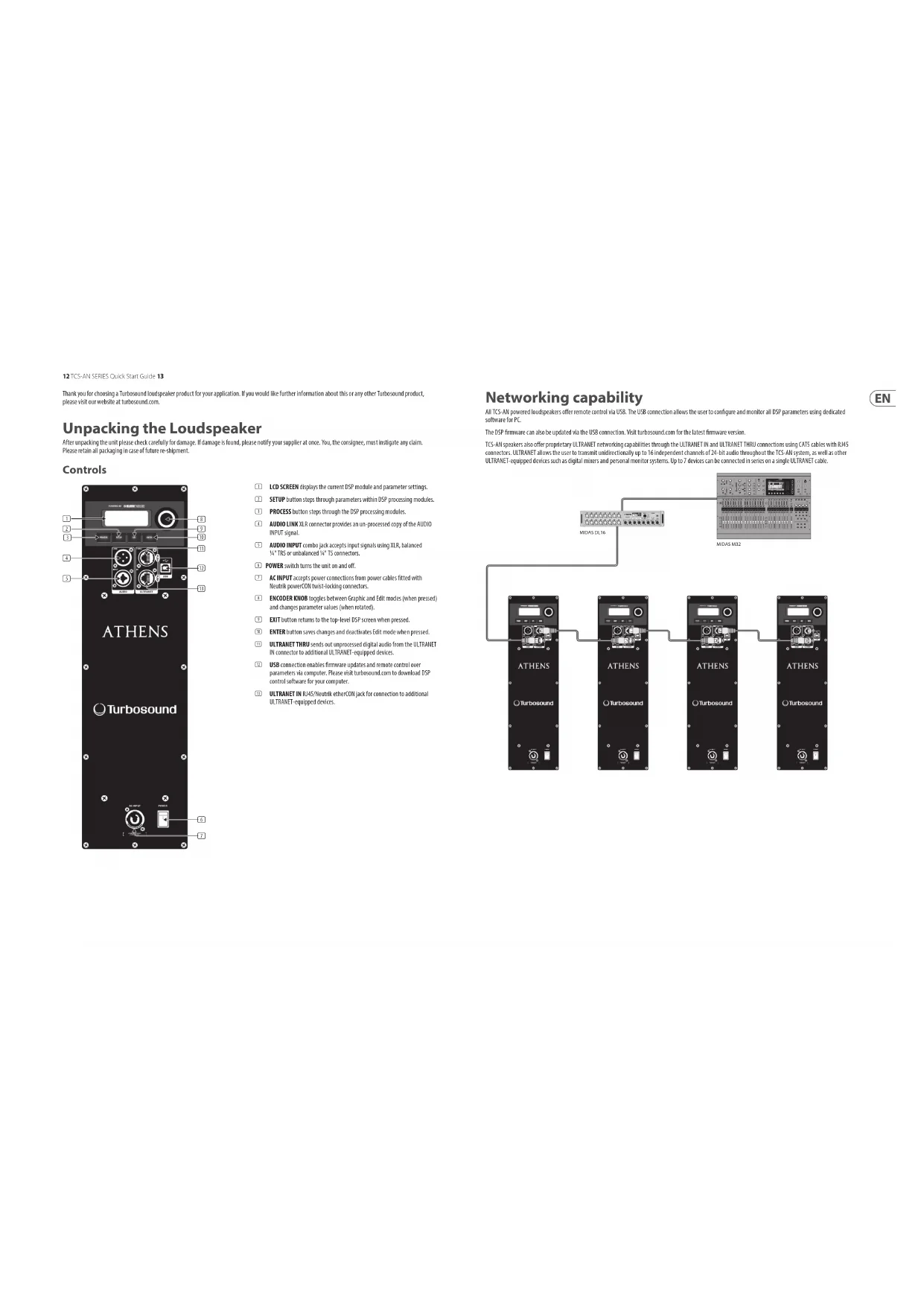
Unpacking the Loudspeaker
After unspaking the unit please check carefully for damage, if damage is found, please notify your supplier at once. You, the consignee, must indicate any claim. Please retain all packaging in case of future re-alignment.
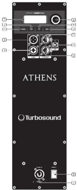
Controls
[1] LCD SCREEN displays the current DSP module and parameter settings.
SETUP button steps through parameters within DSP processing modules.
[3] PROCESS button steps through the BSP processing modules.
(4)AUDIOLINKXLRconnectorprovidesanus-processedcopyoftheAUDIOINPUTsignal.
(T1) AUDIO INPUT comba accepts input signals using XLR, balanced 5^ or unbalanced 4^ connectors.
POWER switch turns the unit on and off.
(7) ACINPUT accepts power connections from power cables fitted with Neutrik powerCON front-loading connectors.
ENCODER KNOB (logopes between Graphic and Edit modes (when pressed) and change parameter values (when mutated).
(5) EXIT button returns to the top-level DSP screen when pressed.
ENTER button saves changes and doactivates Edit mode when pressed.
ULTRANET THRU sends out unprocessed digital audio from the ULTRAET in connector to additional ULTRAET-equipped devices.
USB connection enables firmware updates and remote control over parameters via computer. Please visit turbosound.com to download DSP control software for your computer.
USTRANET IN B45/Seetruth etherCON jack for connection to additional UTRANET equipped devices.
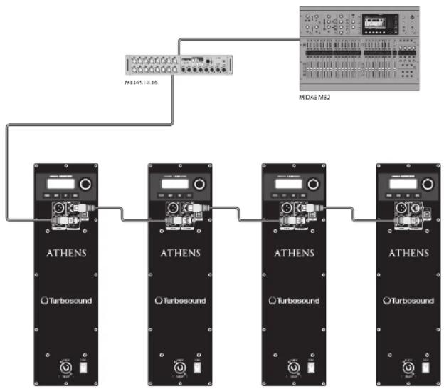
Networking capability
All TCS-AN powered loudspeakers offer remote control via USB. The USB connection allows the user to configure and monitor all DSP parameters using dedicated software for PC.
The DSP firmware can also be updated via the USB connection. Visit turbosound.com for the latest firmware version.
ICS-Ak speakers also offer proprietary ULTRANET networking capabilities through the ULTRANET IN and ULTRANET THRU connections using CAT5 cables with IRAS connectors. ULTRANET allows the user to transmit unidirectionally up to 16 independent channels of Z-B-bit audio throughout the ICS-IN system, as well as other ULTRANET-equipped devices such as digital mixers and personal monitor systems. Up to 7 devices can be connected in series on a single ULTRANET cable.
| PROCESS EQ | Failure Mode Sets the frequency response in the default setting. | ||||
| Reset Mode Sets the frequency response in the default setting. | |||||
| Reset Mode Sets the frequency response in the default setting. | |||||
| Reset Mode Sets the frequency response in the default setting. | |||||
| Reset Mode Sets the frequency response in the default setting. | |||||
| Reset Mode Sets the frequency response in the default setting. | |||||
| Reset Mode Sets the frequency response in the default setting | Sets a corrected frequency response for 2 contacts analysed together. | ||||
| Reset Mode Sets the frequency response in 3 or more contacts analysed together. | |||||
| Reset Mode Sets the frequency response setting by entering the corresponding sub menu. | |||||
| Low/High Shelving Low/High Shelving Sets you define a floor and high shelving filter. | |||||
| Parameter 1 & 2: Parameters 1 & 2 | Let you define a parameter set for EQ (frequency, Qual. and Gain). | ||||
| Reset | Reset | ||||
| HP 100 Hz | LP 150 Hz | Press with 100 Hz, 24 dB/distance filter for crossover between subwoofer and full-range speaker. | |||
| HP 170 Hz | LP 170 Hz | Press with 170 Hz, 24 dB/distance filter for crossover between subwoofer and full-range speaker. | |||
| Reset User | Reset crossover sub menu for combination with other full-range or subwoofer speaker systems. | ||||
| Freq Free | Select the desired crossover frequency: - Full-range System: 75 Hz to 100 Hz. - Subwoofer System: 50 Hz to 150 Hz. | ||||
| Reset | Reset | ||||
| Reset | Reset | ||||
| Reset | Reset | ||||
| Reset | Reset | ||||
| Reset | Reset | ||||
| Reset | Reset | ||||
| Reset | Reset | ||||
| Reset | Reset | ||||
| Reset | Reset | ||||
| Reset | Reset | ||||
| Reset | Reset | ||||
| Reset | Reset | Adjust the absolute phase (0° to 180°). | |||
| Reset | Reset | Automatically sets up many filters required. Whenever a new feedback frequency is discovered, the first filter will be related to attenuate the new frequency, until it has been used. | |||
| Reset | Single | Single | Activates the FREQ feedback detection functionality, up to 8 feedback lattes. | ||
| Reset | Learn | Learn | Automatic procedure which searches for feedback frequencies and offsets after all filters have been used. | ||
| Reset | Reset | Reset | Please use care protection during this procedure. The feedback signal may approach the system's maximum level, which may cause heating damage! | ||
| Reset | Reset | Reset | Reset at filters. | ||
| Reset | Reset | Reset | Lets you choose the sub input source. Choose between local (analogue input) or ULTRABET (e.g., P16 monitoring system or K32 audio via ULTRABET). | ||
| Reset | Volume | Volume | Adjusts the input gain. With ULTRABET digital inputs over a range from -10 dB to -30 dB with analog input from 0 dB to +∞ dB. | ||
| Reset | Sensitivity | Sensitivity | Adjusts input sensitivity for maximum output when using an analogue source +4 dB in real-time operation, +4 dB in high-pass input. | ||
Quick Stee Gultie 15
EN
| Fullrange Subwoofer Function | |||
| POSITION | Free | For positioning the speaker in free suspension or ground stacked away from walls. | |
| Well | For positioning the speaker on or near a wall, or an the floor (bottom) | ||
| Ceiling | For positioning the speaker in a corner near to the ceiling (fixed install at a corner on the floor bottom) | ||
| Screen shot update | DELAY | Delay | Adjust the amount of delay (max 100 msec = 102 m or 138 sec). |
| Unit | Selects between mouse, meters and feet. | ||
| LUMETER | Limit Limit | Adjust the limiter threshold for the input signal from GFF up to 30 dB. This threshold adjustment allows you to set a max output power which is below the knee/upper system's rated max output. | |
| SETUP (Sample 2) | Version | Version Upgrade: installed immature version. | |
| SETUP (Sample 2) USB | 1. 30.1.20. | To load a preset preset turn the encoder is select the desired preset number, and then press either the ENTER button or the mouse. When asked to confirm press the encoder again or DUT is absent. | |
| SETUP (Sample 2) SWITCH | 1. 30.1.20. | To save a preset choose the respective preset driver and press ENTER or the encoder. | |
| SUB MENU (Sample 2) Save Preset | Save Preset | Name the preset by choosing the characters with the encoder and pressing to confirm each character. When finished, press the ENTER button to save the preset. | |
| SUB MENU (Sample 2) Switch | Contrast | Adjust LCD panel contrast. The default contrast value is 1%. | |
| ATHENS (Sample 2) Screen Screen | On LCD screen screen (default) turns on automatically after approx. 2 minutes. OFF LCD turn off automatically when approx. 5 minutes. | ||
| ATHENS (Sample 2) Sub Menu | Lock | Lock the device and create a password by checking the password characters with the encoder and pressing to confirm each character. When finished, press the ENTER button. Lock the device entering the password or connecting the unit via USB to a PC running proprietary remote software. Enter software does not require a password. | |
| Warning | Warning In some cases, an alert appears on the LCD screen, and the amplifier will shut down until the unit icon | ||
16 TCSANSERIES
LCD Graphic Indicators
To help the user immediately recognize that a parameter has been selected and changed from the initial default setting, the parameter's related text on the top-level screen will invert and change to black text on a white background. As an example, the following screenshot shows how the text for the EQ function changes when the TCS-All default EQ setting has been changed:

This indicator function occurs only on the main DSP menu level and works for all DSP-related functions, except for the LOAD, SAVE and SEUP sub-sections on the second page of the top-level SETUP menu.
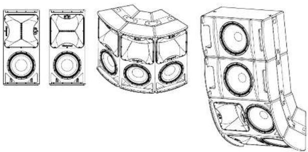
Mounting and Fixing
The table below summarises the rigging parts or kits required for various applications, and some examples of the possible rigging options are illustrated.
TC5-NI series cabinets are designed with multiple internal zigging points to suit many possible mounting methods in permanent installations. All cabinets can be simply suspended using optional MB or MTG shoulder eyebouts coupled to the internal zigging points provided. Remove the appropriate counter-scan screws and replace them with eyebouts, which must have a thread length of at least 18mm . Use the rear zigging point to angle the cabinet for optimum room coverage. Cabinets may be hung upside down if required. Turquoise WB-SS and CB-SS wall and ceiling brackets are optionally available for TCS-NI series cabinets, and these are also compatible with industry standard wall and ceiling brackets which use 50mm × 60mm hole spacing.
| Model | Well | Ceiling | Downfall | Arrow Kit | Eyebolts |
| TCS122 V95-33 C0-33 | TCS122 FP TCS-FR1 TCS-FQ2 | B-10-40 | |||
| TCS122 V95-33 C0-33 | TCS122 FP TCS-FR1 TCS-FQ2 | B-10-40 | |||
| TCS1158 | TCS1158 FP TCS-FR3 | B-10-40 | |||
| TCS Subtotal E10-40 |
Some typical examples of the possible rigging options are shown here:
Quick Ss. 17

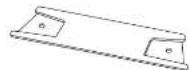
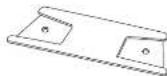
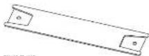
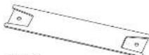
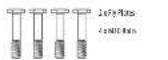
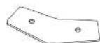
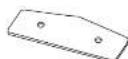
TCS-AN Series Flying Components
Wall and Ceiling Brackets
To install a loudspeaker using Turbosound wall and ceiling brackets, first separate the brackets into their wall/ceiling plate and speaker plate component parts. Remove the countersun bolts on the rear panel of the cabinet. Attach the speaker plate to the cabinet with the bolts supplied. Fix the wall/ceiling plate in the venue using appropriate fixtures (not supplied). Lift the loudspeaker on to the wall plate and re-assemble the bracket parts, adjust the vertical angle and tighten all bolts.
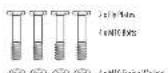
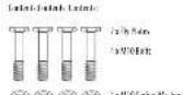
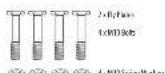
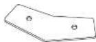
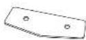
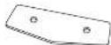
Loudspeaker Arrays and Clusters
An array of two or more cabinets requires the use of slits of flasks and later-cabinet cuppers, which are fixed to the cabinet slides through the WIT rigging points and assembled together in a 'daisy chain' fashion to build up the required array. For loudspeaker arrays consisting of two or more cabinets:
The number of intercabinet coupler kits required the number of boxes 1, The number of flyplate kits required the number of boxes.
Illustrated here are the components parts available for ICS cabinets.
TSS162P00H 1F
100
108-114
:NTBCB2
中
E-104048
1.2.3.2.2.2.2.2.2.2.2.2.2.2.2.2.2.2.2.2.2.2.2.2.2.2.2.2.2.2.2.2.2.2.2.2.2.2.2.2.2.2.2.2.2.2.2.2.2.2.2.2.2. 569
Socicty 1, 2, 4, 6
31.41000
32.41000
33.41000
34.41000
RQ BQ CRRI RCRS CRRS CRRS CRRS CRRS CRRS CRRS CRRS CRRS CRRS CRRS CRRS CRRS CRRS CRRS CRRS CRRS CRRS CRRS CRRS CRRS CRRS CRRS CRRS CRRS CRRS CRRS CRRS CRRS CRRS CRRS CRRS CRRS CRRS CRR

B-14
EcoV700
Covid-19
18 TCSANSERIES
Quick Start 19
Suspending with Eyebolts
TCS-VM Cachinrs can be suspended using optional eyebloits coupled to the internal riging points provided on the top, bottom and sides and back. The simplest method is to use the two rigging points on the top and a single pull-back rigging point in the centre of the rear panel.
Remove the appropriate counterclock screws and replace them with shoulder wedels, which must have a thread length of at least 18mm . Use the rearing point to angle the cabinet for optimum warm coverage. Cabinet may be hung upside down if required.
IMPOPTN TOTE AALLIATIONMETHoN:The mouning of a permanently installed sound system may be dangerous unless undertaken by quittified personnel with the required experience and certification to perform the necessary tasks. Walls, floors or ceilings must be capable of safety and securitly superting the actual load. The mounting accessory used must be safe and securely fixed both to the loudspeaker and to the wall, floor or ceiling.
When mounting digging components on walls, floors or ceilings, ensure that all fittings and fasteners used are of an appropriate size and load rating. Wall and ceiling claddings, and the construction and composition of walls and ceilings, all need to be taken into account when determining whether a particular fixing arrangement can be safely employed for a particular load. Vanity plugs or other specialist fixings, if required, must be of an appropriate type, and must be fitted and used in accordance with the maker's instructions.
The operation of your speaker cabinet as part of a flow system, if installed incorrectly and improperly, can potentially expose persons to serious health risks and even death. In addition, please ensure that electrical, mechanical and acoustic considerations are discussed with qualified and certified (by local state or national authorities) personnel prior to any installation or flying.
Make sure that speaker cabinets are set up and flown by qualified and certified personnel only, using dedicated equipment and original parts and components delivered with the unit. If any parts or components are missing please contact your Dealer before attempting to set up the system.
Be sure to observe the local, state and other safety regulations applicable in your country. Music Tribe, including the Music Tribe companies listed on the enclosed "Service Information Sheet", assumes no liability for any damage or personal injury resulting from improper use, installation or operation of the product. Regular checks must be conducted by qualified personnel to ensure that the system remains in a secure and stable condition. Make sure that, where the speaker is known, the area underneath the speaker is free of human traffic. Do not fly the speaker in areas that can be entered or used by members of the public.
Speakers create a magnetic field, even if not in operation. Therefore, please keep all materials that can be affected by such fields (disco, computers, monitors, etc) at a safe distance. A safe distance is usually between 1 and 2 metres.
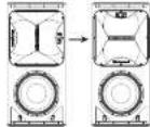
Rotating the HF horn pattern
The high frequency in all TCS122 and TCS152 models can be rotated through 90^ in order to swap the horizontal and vertical dispersion patterns, particularly useful when assembling clusters or for example to retain the original dispersion when the cabinet is installed in a horizontal orientation.
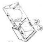
- Place the cabinet on its back on a suitable work surface.
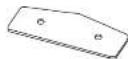
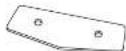
- Remove the 10 posirde screws that hold the grille in place and set the grille aside (Fig 1).
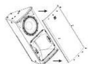
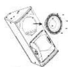
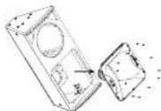
- Remove and disconnect the bass driver (fig 2) to access the compression driver retaining brace, making a note of the bass driver polarity for later reconnection.
- Reach in through the bass driver cavity and loosen the two wing nuts securing the compression driver retaining brace (fig 3).
-
Remove the horn fixing screws that secure the horn to the enclosure and lift out the horn and compression driver assembly (fig 4), (required for servicing or replacement, disconnect the cables from the compression driver, making a note of the polarity for later reconnection).
-
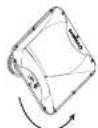
Rotate the horn to achieve the desired coverage pattern [fig 5].
-
Iie-assemble the cabinet and drivers by reversing steps 1-S
-
If the compression driver cables have been disconnected, reconnect the cables while observing the correct polarity (white cable to the -ve terminal, black cable to the -ve terminal).
- Place the horn and compression driver back into the cabinet, making sure that the driver cables pass underneath the compression driver retainer and that the compression driver fits snugly back into the retaining bolt.
- Tighten the wing nuts back onto the compression driver retaining brace [fig 3].
- Replace the horn firing screws and tighten to secure the horn back into the enclosure (fig 4).
- Recnect the bass drive cables, observing the correct polarity'led cable to the -ve terninal, blue cable to the -ve terminal.
-
Check all components and confirm the horn orientation is correct (fig 6).
-
Regass the strike (the) and phase stock the cabinet before you.
与
1
10
EN
TST15#NAM
100000000000000000000000000000000000000000000000
C
TSG101CIM
Auto Control Control for TSG102 on TSG102
Company 2012
5237840
Intra Cline Coqge 192158
Scriber 1610
1040218D
1040218D
1040218D
1040218D

1-12-2
Ftdc10100000
Cofn 11100000
NL
RPG配置
Enter Control Settings for CPU22 or CPU23
system /etc

B-14
EcoV700
Covid-19
Technical Specifications
TCS122/64-AN-WH)TC5122/94-AN-WH)TC5122/96-AN-WH)TC5152/64-AN-WH
| System | ||||
| Frequency response | 50Hz-18kHz±3dB45Hz-20kHz-10dB | 50Hz-18kHz±3dB45Hz-20kHz-10dB | 50Hz-18kHz±3dB45Hz-20kHz-10dB | 41Hz-18kHz±3dB35Hz-20kHz-10dB |
| Nominal dispersion | 60° II x 40° III x 40° points, unstable | 90° II x 40° IV x 60° points, unstable | 90° II x 60° IV x 60° points, unstable | 60° II x 60° V S x 60° points, unstable |
| Maximum I.P. 131 dB peak 131 dB peak 131 dB peak 131 dB peak | ||||
| Commonspeclal Active Active Active | ||||
| Transducers | 1 x 12° (312 mm)LF Driver1 x 1.4° (266 mm)HF compression driver | 1 x 12° (313 mm)LF Driver1 x 1.4° (266 mm)HF compression driver | 1 x 12° (313 mm)LF Driver1 x 1.4° (266 mm)HF compression driver | 1 x 12° (394 mm)HF Driver1 x 1.4° (266 mm)HF compression driver |
| Diameter | Independent DC, 10 pKa/s (250 W) | Independent DC, 10 pKa/s (250 W) | Independent DC, 10 pKa/s (250 W) | Independent DC, 10 pKa/s (250 W) |
| Amplitude | ||||
| Maximum output power: 2500 W/2500 W/2500 W | ||||
| Type-class-0 Class-0 Class-0 | ||||
| Protection | Short circuit, thermal | Short circuit, thermal | Short circuit, thermal | Short circuit, thermal |
| Connectors | ||||
| Input/Output | 1 x Combo jack/ULB, 1 x ULB | 1 x Combo jack/ULB, 1 x ULB | 1 x Combo jack/ULB, 1 x ULB | 1 x Combo jack/ULB, 1 x ULB |
| Sensitivity | +4 dBi or +4 dBi software switchable | +4 dBi or +4 dBi software switchable | +4 dBi or +4 dBi software switchable | +4 dBi or +4 dBi software switchable |
| Input impedance | 60 kΩ balanced | 40 kΩ balanced | 40 kΩ balanced | 40 kΩ balanced |
| Maximum input load | +22 dBi | +22 dBi | +22 dBi | +22 dBi |
| Ultrasound input/Output | 2 x BARS | 2 x BARS | 2 x BARS | 2 x BARS |
| Males Supply | Neutral powerCON 20A | Neutral powerCON 20A | Neutral powerCON 20A | Neutral powerCON 20A |
| CBS | ||||
| DSP | Binary push encoder and base on control Buttons for Process, Setup, Wait, Init | Binary push encoder and base on control Buttons for Process, Setup, Wait, Init | Binary push encoder and base on control Buttons for Process, Setup, Wait, Init | Binary push encoder and base on control Buttons for Process, Setup, Wait, Init |
| Outer DSP Functions | ||||
| Factory ID, Presens | Poisiting, Sound mode, FQI | Poising, Sound mode, FQI | Poising, Sound mode, FQI | Fickling, Snd mode, FQI |
| Display | LCD 128 x 32, blue, blackfit | LCD 128 x 32, blue, blackfit | LCD 128 x 32, blue, blackfit | LCD 128 x 32, blue, blackfit |
| Delay | 0 - 100 ms | 0 - 100 ms | 0 - 900 ms | 0 - 900 ms |
| Equationation | High and low shunting EQI 2 parameters EQI | High and low shunting EQI 2 x parameteric EQI | High and low shunting EQI 2 x parameteric EQI | High and low shunting EQI 2 x parameteric EQI |
| Limit | Zero attack input limiter | Zero attack input limiter | Zero attack input limiter | Zero attack input limiter |
| Prests | 20 total prsents 19 user-detectable | 20 total prsents 19 user-detectable | 20 total prsents 19 user-detectable | 20 total prsents 19 user-detectable |
| Crossover | High Pass L-R 24 all set | High Pass L-R 24 all set | High Pass L-R 24 all set | High Pass L-R 24 all set |
| Protection | Lock-out function for all settings | Lock-out function for all settings | Lock-out function for all settings | Lock-out function for all settings |
Quick Start Guide 85
EN
TCS122/84-AN(-WH)TCS122/94-AN(-WH)TCS122/96-AN(-WH)TCS152/64-AN(-WH)
| Digital processing | ||||
| A/D conversion | 24-bit, 64/78 Hz sample rate | 24-bit, 64/78 Hz sample rate | 24-bit, 64/78 Hz sample rate | 24-bit, 64/78 Hz sample rate |
| Converter type | 24-bit delta-sigma | 24-bit delta-sigma | 24-bit delta-sigma | 24-bit delta-sigma |
| System | ||||
| Signal | 16 channels | 16 channels | 16 channels | 16 channels |
| Latency | <0.9 ms | <0.9 ms | <0.5 ms | <0.5 ms |
| Frequency response | 20Hz to 20kHz(+0.7-3dB) | 20Hz to 20kHz(+0.7-3dB) | 20Hz to 20kHz(+0.7-3dB) | 20Hz to 20kHz(+0.7-3dB) |
| Dynamic range | Typical 92 dB | Typical 92 dB | Typical 92 dB | Typical 92 dB |
| Cabling | ||||
| Cables | Shielded COTS | Shielded COTS | Shielded COTS | Shielded COTS |
| Cable length | max. 246Ω/1.75 m recommended | max. 246Ω/1.75 m recommended | max. 246Ω/1.75 m recommended | max. 246Ω/1.75 m recommended |
| Voltage (p.u.) | ||||
| Power consumption | 90 W x 2 max power | 50 V x 2 max power | 50 W x 2 max power | 90 W x 2 max power |
| USA / Canada | 120 V - 50Hz(1.5 A H 250 V) | 120 V - 60 Hz(1.5 A H 250 V) | 120 V - 60 Hz(1.5 A H 250 V) | 120 V - 60 Hz(1.5 A H 250 V) |
| UK / Australia / Europe | 220-240 V - 500Hz(T.10 A H 350 V) | 220-240 V - 500Hz(T.10 A H 350 V) | 220-240 V - 500Hz(T.10 A H 350 V) | 220-240 V - 500Hz(T.10 A H 350 V) |
| Korea / China | 220-240 V - 500Hz(T.10 A H 250 V) | 220-240 V - 500Hz(T.10 A H 250 V) | 220-240 V - 500 Hz(T.10 A H 250 V) | 220-240 V - 500 Hz(T.10 A H 250 V) |
| Japan | 120 V - 500Hz(T.15 A H 150 V) | 105 V - 500Hz(T.15 A H 150 V) | 102 V - 500 Hz(T.15 A H 150 V) | 100 V - 500 Hz(T.15 A H 150 V) |
| Endorse | ||||
| Dimensions (M/0) | 834 x 359 x 425 mm(32.8 x 15.7 x 16.7") | 834 x 399 x 425 mm(32.8 x 15.7 x 16.7") | 834 x 399 x 425 mm(32.8 x 15.7 x 16.7") | 834 x 43 x 451 mm(32.8 x 16.6 x 17.8") |
| Net weight | 27.8 kg (SL12B) | 27.8 kg (SL12 B) | 27.8 kg (SL12B) | 32.6 kg (SL13 B) |
| Construction | 15 mm (7" thick plywood) | 15 mm (7" thick plywood) | 15 mm (7" Birch plywood) | 15 mm (7" Birch plywood) |
| Finish | Semi matt black paint(white optional) | Semi matt black paint(white optional) | Semi matt black paint(white optional) | Semi matt black paint(white optional) |
| Giraffe | Provider coated perforated steel | Provider coated perforated steel | Powder coated perforated steel | Powder coated perforated steel |
| Flying hardware | MTX 2.9, MTX 8.5 points | MTX 9, MTX 8.5 points | MTX 9, MTX 8.5 points | MTX 9, MTX 8.5 points |
| Accessories | TCS152 FP (WIFI Phy plate kit for TCS152) | TCS152 FP (WIFI Phy plate kit for TCS152) | TCS152 FP (WIFI Phy plate kit for TCS152) | TCS152 FP (WIFI Phy plate kit for TCS152) |
| TCS-FOL WIFI Inter-cabinet, coupled kit for TCS152 or TCS152 | TCS-FOL WIFI Inter-cabinet, coupled kit for TCS152 or TCS152 | TCS-FOL WIFI, inter-cabinet, coupled kit for TCS152 or TCS152 | TCS-FOL WIFI, inter-cabinet, coupled kit for TCS152 or TCS152 | |
| TCS-FOL WIFI Inter-cabinet, coupled kit for TCS152 with TCS152 or TCS152 | TCS-FOL WIFI Inter-cabinet, coupled kit for TCS152 with TCS152 or TCS152 | TCS-FOL WIFI, inter-cabinet, coupled kit for TCS152 with TCS152 or TCS152 | TCS-FOL WIFI, inter-cabinet, coupled kit for TCS152 with TCS152 or TCS152 |
Technical Specifications
Quick Start Guide 87
EN
TCS152/94-AN-WH)TCS152/96-AN-WH)TCS115B-AM(WH)TCS218B-AN(WH)
| Frequency response | 41 Hz - 18 kHz ± 1 dB 35 Hz - 20 kHz ± 10 dB | 41 Hz - 18 kHz ± 1 dB 35 Hz - 20 kHz ± 10 dB | 45 Hz - 150 Hz ± 1 dB 40 Hz - 200 Hz ± 10 dB | 33 Hz - 200 Hz ± 1 dB 27 Hz - 200 Hz ± 10 dB |
| Nominal dispersion | 92° II × 40° V @ 6.48 points, variable | 90° II × 60° V @ 6.48 points, variable | Fair Space Hall Space | |
| Maximum SPL 133 dB peak 133 dB peak 133 dB peak 133 dB peak | ||||
| Common source active active active active | ||||
| Transducers | 1 x 15" (34 mm) [L Driver 1 x 15" (36 mm) Hf composition driver] | 1 x 15" (34 mm) [L Driver 1 x 15" (36 mm) Hf composition driver] | 1 x 15" (38 mm) [L driver /] Hf composition driver] | 2 x 15" (460 mm) [L driver /] Hf composition driver] |
| Limiter | Independent HF, L peaks and ms | Independent HF, L peak and ms | Peak and rms | Peak and rms |
| Amplitude | ||||
| Maximum output power* | 2500 V | 2500 V | 3000 W | 4000 W |
| Type | Class-D | Class-D | Class-B | Class-B |
| Protection | Short circuit, thermal | Short circuit, thermal | Short circuit, thermal | Short circuit, thermal |
| Connector | ||||
| Inputlink | 1 x Combo jack/ULB 1 x ULB | 1 x Combo jack/ULB 1 x ULB | 1 x Combo jack/ULB 1 x ULB | 1 x Combo jack/ULB 1 x ULB |
| Sensitivity | +4dB or +14 dBi software switchable | +4dB or +14 dBi software switchable | +4dB or +14 dBi software switchable | +4dB or +14 dBi software switchable |
| Input impedance | 40 kΩ balanced | 40 kΩ balanced | 40 kΩ balanced | 40 kΩ balanced |
| Maximum input level | +22 dBi | +22 dBi | -22 dBi | -22 dBi |
| Ultimate inputlink | 2 x RMS | 2 x RMS | 2 x RMS | 2 x RMS |
| Matrix Supply | Reset powerCOB 206 | Reset powerCOB 206 | Reset powerCOB 206 | Reset powerCOB 206 |
| Controls | ||||
| DSP | Binary push-encoder and level control | Binary push-encoder and level control | Binary push-encoder and level control | Binary push-encoder and level control |
| Buttons for Process, Setup, Init, Init | Buttons for Process, Setup, Init, Init | Buttons for Process, Setup, Init, Init | Buttons for Process, Setup, Init, Init | |
| Use DSP Functions | |||||
| Factory EO Frequens | Positioning,Sound mode,FIR | Positioning,Sound mode,FIR | Positioning,Sound mode | Positioning,Sound mode | |
| Display | LCD 128 x 32, blue, blackfit | LCD 128 x 32, blue, blackfit | LCD 128 x 32, blue, blackfit | LCD 128 x 32, blue, blackfit | |
| Delay | 0-300 ms 90ms 300 ms 90ms | 300 ms 90ms 300 ms | 300 ms 90ms 300 ms | 300 ms 90ms 300 ms | |
| Equation | High and low shunting E0 2 x parameter E0 | High and low shunting E0 2 x parameter E0 | High and low shunting E0 2 x parameter E0 | High and low shunting E0 2 x parameter E0 | |
| Limit | Zero attack input limiter | Zero attack input limiter | Zero attack input limiter | Zero attack input limiter | |
| Preset | 20 total presets, 19 pre-determines | 20 total presets, 19 pre-determines | 20 total presets, 19 pre-determines | 20 total presets, 19 pre-determines | |
| Crossover | High Pass I-R2R cutoff | High Pass I-R2R cutoff | Low Pass I-R2R cutoff | Low Pass I-R2R cutoff | |
| Protection | Lock-out function for all settings | Lock-out function for all settings | Lock-out function for all settings | Lock-out function for all settings | |
TCS152/94-AN-WHTCS152/96-AN-WHTCS115B-AN(WH)TCS218B-AN(WH)
| Upto net Digital Network | ||||
| Digital processing | ||||
| A/D conversion | 24-bit, 64.1/8Hz sample rate | 24-bit, 64.1/8Hz sample rate | 24-bit, 64.1/8Hz sample rate | 24-bit, 64.1/8Hz sample rate |
| Converter type | 34-bit delta-sigma | 24-bit delta-sigma | 24-bit delta-sigma | 24-bit delta-sigma |
| System | ||||
| Signal | 16 channels | 16 channels | 16 channels | 16 channels |
| Latency | <0.9 ms | <0.9 ms | <0.5 ms | <0.5 ms |
| Frequency response | 20Hz to 20MHz(+/-3dB) | 20Hz to 20MHz(+/-3dB) | 20Hz to 20MHz(+/-3dB) | 20Hz to 20MHz(+/-3dB) |
| Dynamic range | typical 92 dB | typical 92 dB | typical 92 dB | typical 92 dB |
| Cabling | ||||
| Cables | Shielded COTS | Shielded COTS | Shielded COTS | Shielded COTS |
| Cable length | max. 246L/1.75 m recommended | max. 246L/1.75 m recommended | max. 246L/1.75 m recommended | max. 246L/1.75 m recommended |
| Voltage (p.u.) | Power consumption | 90 W max power 90 V at | Max power | 100 W at max power | 350 W at max power |
| USA / Canada | 120 V - 50 Hz(T 15 A + 250 V) | 125 V - 60 Hz(T 15 A + 250 V) | 120 V - 60 Hz(T 15 A + 250 V) | 120 V - 60 Hz(T 15 A + 250 V) | |
| UK / Australia / Europe | 220-240 V - 500 Hz(T 10 A + 150 V) | 220-240 V - 500 Hz(T 10 A + 150 V) | 220-240 V - 500 Hz(T 10 A + 150 V) | 220-240 V - 500 Hz(T 10 A + 150 V) | |
| Korea / China | 220-240 V - 500 Hz(T 10 A + 250 V) | 220-240 V - 500 Hz(T 10 A + 250 V) | 220-240 V - 500 Hz(T 10 A + 250 V) | 220-240 V - 500 Hz(T 10 A + 250 V) | |
| Japan | 120 V - 500 Hz(T 15 A + 150 V) | 100 V - 500 Hz(T 15 A + 150 V) | 100 V - 500 Hz(T 15 A + 150 V) | 100 V - 500 Hz(T 15 A + 150 V) |
| Endorse | |||
| Dimensions (H/D) | 834 x 413 x 457 mm (32.6 x 18.6 x 17.8") | 834 x 473 x 451 mm (33.8 x 18.6 x 17.8") | 534 x 469 x 452 mm (33.8 x 18.6 x 17.8") |
| Net weight | 30.6 kg (67.5 lbs) | 30.6 kg (67.5 lbs) | 34.5 kg (75.5 lbs) |
| Construction | 15 mm" D"刨花 plywood | 15 mm" D" Bitch plywood | 15 mm" C" Birch plywood |
| Finish | Semi matt black paint (white optional) | Semi matt black paint (white optional) | Semi matt black paint (white optional) |
| Girth | Powder coated perforated steel | Powder coated perforated steel | Powder coated perforated steel |
| Drying procedure | MTX v MTX 8 sheets | MTX 8, MTX 8 sheets | MTX 8 |
| Accessories | |||
| TCS152 FP 1/4 MHD Fly plate kit for TCS152 | TCS152 FP 1/4 MHD Fly plate kit for TCS152 | TCS152 FP 1/4 MHD fly plate kit for TCS152 | |
| TCS-FC1 4MHD Inter-cabinet coupler kit for TCS152 or TCS152 | TCS-FC1 4MHD Inter-cabinet coupler kit for TCS152 or TCS152 | TCS-FC1 4MHD inter-cabinet coupler kit for TCS152 or TCS152 | |
| TCS-FC1 4MHD Inter-cabinet coupler kit for TCS152 with TCS152 or TCS152 | TCS-FC1 4MHD Inter-cabinet coupler kit for TCS152 with TCS152 | TCS-FC1 4MHD inter-cabinet coupler kit for TCS152 | |
* independent of limiters and driver protection circuits
† Only qualified personnel are allowed to modify the AC-Man cond and to adhere to all applicable national standards.

TC-ANSEBES
Other important information

Important information

Informations importantes

- Registrar online. Registrar don't give Mekwi tribe-tributary direct after act but opt to gain an email at his/her tribe.com. At registrar site it copied many veridical online templates and sent by hand to a regional administration agency that can offer relief. This adds little risk for the parent to claim relief.
Responsible Party Name: Music Tribe Commercial NV Inc.
Address: 5270 Procyon Street,
Las Vegas NV 89118, United States
Phone Number: +1 702 800 8290
TCS-AN SERIES
This equipment has been tested and found to comply with the limits for a Class 4 digital device, pursuant to part 15 of the FCC Rules. These limits are designed to provide reasonable protection against harmful interference when the equipment is operated in a commercial environment. This equipment generates, uses, and can radiate radio frequency energy, and if not introduced and used in accordance with the Federal Aviation Act, may cause harmful interference to radio communications. Operation of this equipment in a residential area is likely to cause harmful interference in which case the user will be required to correct the interference at his own expense.
This device complies with Part 15 of the FC rules. Operation is subject to the following two conditions:
[1] this device may not cause harmful interference, and
[2] this device must accept any interference received, including interference that may cause undesired operation.
Warning: Operation of this equipment in a residential environment could cause radio interference.
Important information:
Changes or modifications to the equipment not expressly approved by Music Therapy can void the user's authority to use the equipment.
CE
Hence, MUSIC obeote that this product is in compliance with Directive 2014/657/U, Directive 2014/957U, Directive 2011/657U and Amendment 2015/853-U, Directive 2012/75U, Regulation 517/2012 RS&DS 518C and Directive 1907/2006-EC.
Full text of EU Doc is available at https://community.muskrife.com
EU Representative Music Tribe Brands DK A/S
Address: In Spang Obers Gade 17, DR - 8200 Anhuis, Denmark
Quick Start Guide 91