W4200 - Home Theater System DELL - Free user manual and instructions
Find the device manual for free W4200 DELL in PDF.


| Product Type | Home theater system / Plasma display TV |
| Brand | Dell |
| Model | W4200 |
| Variants | W4200ED (enhanced definition) and W4200HD (high definition) |
| Screen size | 106 cm (42 inches), 16:9 format |
| Native resolution | W4200HD: 1024 x 768 (XGA); W4200ED: 852 x 480 (WVGA) |
| Brightness | W4200ED: 450 nits; W4200HD: 420 nits |
| Contrast ratio | W4200ED: 2700:1; W4200HD: 2300:1 |
| Viewing angle | Horizontal and vertical: +/- 80 degrees |
| Dimensions (with stand) | 1031.8 x 712.5 x 245.7 mm |
| Dimensions (without stand) | 1031.8 x 631.5 x 83.8 mm |
| Weight (with stand) | Approximately 46 kg |
| Input connections | HDMI, DVI, VGA, composite (x3), S-Video (x3), component (x2), coaxial TV (NTSC/ATSC) |
| Output connections | Composite, audio (RCA), subwoofer, SPDIF (optical and coaxial on HD) |
| Audio power | 20 watts per channel (40 watts total) |
| Audio technologies | SRS TruSurround XT, Midnight mode, equalizer |
| Image functions | PIP, POP, PBP, multiple image settings (cinema, sports, etc.) |
| Parental control | Yes (channel lock, movie/TV ratings) |
| Other functions | SAP, closed captioning, auto sleep, plasma conditioning |
| Power supply | 100-240 V AC (built-in power adapter) |
| Maintenance | Wipe with a soft damp cloth; do not use chemical products |
| Safety instructions | Do not open, ensure ventilation, avoid shocks and humidity |
| Included accessories | Remote control, AAA batteries (x2), power cord, antenna cable, documentation |
| Repairability | Only a qualified technician should service the device |
Frequently Asked Questions - W4200 DELL
User questions about W4200 DELL
0 question about this device. Answer the ones you know or ask your own.
Ask a new question about this device
Download the instructions for your Home Theater System in PDF format for free! Find your manual W4200 - DELL and take your electronic device back in hand. On this page are published all the documents necessary for the use of your device. W4200 by DELL.
USER MANUAL W4200 DELL
Notes, Notices, and Cautions
Throughout this document, blocks of text may be accompanied by an icon and printed in bold or italic type. These blocks are notes, notices, and cautions, and they are used as follows:

NOTE: A NOTE indicates important information that helps you make better use of your TV.

NOTICE: A NOTICE indicates either potential damage to hardware and tells you how to avoid the problem.

CAUTION: A CAUTION indicates a potential for property damage, personal injury, or death.
Information in this document is subject to change without notice.
© 2004 Dell Inc. All rights reserved.
Reproduction of this document in any manner whatsoever without the written permission of Dell Inc. is strictly forbidden.
Trademarks used in this text: Dell, the DELL logo; SRS(●) TruSurround XT TruSurround XT, SRS, and (●) symbol are trademarks of SRS Labs, Inc.
Other trademarks and trade names may be used in this document to refer to either the entities claiming the marks and names or their products. Dell Inc. disclaims any proprietary interest in trademarks and trade names other than its own.
October 2004 Rev. A00
Contents
1 About Your TV
Front View 5
Right View 6
Bottom View 7
Package Contents 9
Caring for Your TV 10
2 Setting Up Your TV
Proper Location for Your TV 11
Connecting Your TV 12
3 Your Remote Control
Installing Batteries 19
Using Your Remote Control 20
Using Your Remote Control 22
Using Your TV With a Universal or Learning Remote Control. 24
4 Using the On-Screen Display
Using Your Remote Control With the OSD 25
Selecting Your OSD Language 26
Input Select 26
Picture Menu 28
Audio 28
PIP/POP/PBP 29
Size 30
Parental Control 30
Setup 31
5 Troubleshooting Problems With Your TV
Troubleshooting Tips 33
General Problems 34
OSD Messages 38
Remote Control Problems 38
Using the Self-Test Feature when Connected to a Computer 39
Problems When Using the TV Display as a Monitor 39
6 Specifications for Your TV
Index 45
About Your TV
Front View
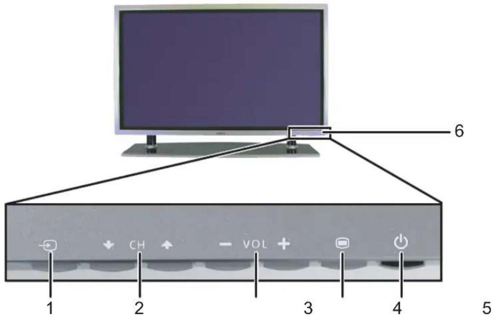
| 1 | Input Source button | Push to display the Input Select menu |
| 2 | Channel up/downbutton | Push to select the previous/next channel or navigate through the on-screen display (OSD) menu |
| 3 | Volume up/downbutton | Push to increase/decrease the volume or to select an OSD option |
| 4 | OSD Menu button Push to display the OSD menu | |
| 5 | Power button and light(LED) | Push to turn the TV on and offThe power light is blue when the TV is on and amber when it is in power saving mode |
| 6 | IR receiver Senses the signal from the remote control | |
Right View
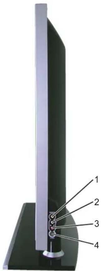
| 1 | Composite video connector (AV7) | Connect devices such as a VCR or DVD player |
| 2 | Audio connector (L) | Use this connector if you have connected a device to the composite connector (AV7) or the S-Video connector (AV8) |
| 3 | Audio connector (R) | Use this connector if you have connected a device to the composite connector (AV7) or the S-Video connector (AV8) |
| 4 | S-Video input (AV8) | Connect devices such as a video game system, a digital camera, or a DVD player |
Bottom View
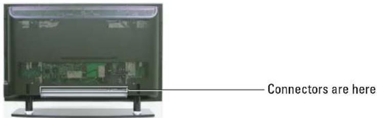
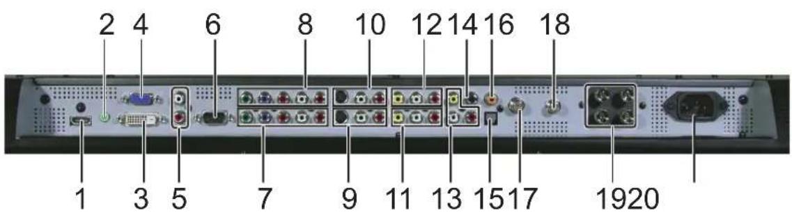
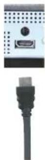
1 HDMI connector Connect devices such as a DVD player or set-top box
2 Audio connector for VGA Connect the audio cable from your computer to the TV
3 DVI connector Connect devices such as a DVD player, set-top box, or your computer
4 VGA connector Connect to the VGA cable from your computer to the TV
5 DVI audio connectors (R/L) Connect to the DVI audio connectors if you have connected a device such as a DVD player or set-top box to the DVI connector
6 RS232 For factory use only
7 Component audio and video connectors (AV2) Connect devices such as a DVD player, set-top box, or cable TV box
8 Component audio and video connectors (AV1) Connect devices such as a DVD player, set-top box, or cable TV box
9 S-Video connectors (AV4) Connect devices such as a video game system or a DVD player
10 S-Video connectors (AV3) Connect devices such as a video game system or a DVD player
11 Composite video and audio connectors (AV6) Connect devices such as a VCR or DVD player
12 Composite video and audio connectors (AV5) Connect a device such as a VCR or DVD player
| 13 Composite video and audio-out connectors | Connect a device such as a VCR if you have connected an antenna or cable TV through the ANT/Cable connector |
| 14 Subwoofer audio out | Connect an optional powered subwoofer to the TV |
| 15 Optical digital out (SPDIF) (for W4200HD only) | Connect an audio decoder or audio/video receiver |
| 16 Coaxial digital audio out (for W4200HD only) | Connect an audio decoder or audio/video receiver when using a Digital TV (ATSC connector) |
| 17 ATSC connector (for W4200HD only) | Connect an antenna for the digital tuner when using Digital TV (ATSC connector) |
| 18 NTSC connector Connect an antenna or a cable TV box | |
| 19 Speaker out connectors Connect speakers | |
| 20 Power connector Connect your power cord | |
Package Contents

NOTE: If you need additional cables, contact Dell.
Remote control
AAA batteries (2)
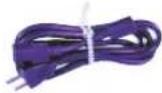
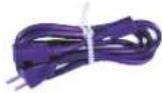
Power cord
Antenna (coaxial) cable
Documentation
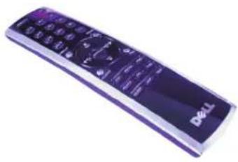
natural_image
Exterior view of a Dell remote control device (no visible text or symbols on the device body)

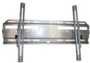
Wall mount (optional)
Speakers (optional)
Stand hole cover (2)
natural_image
Metallic rectangular frame with flanged supports and central cutouts (no text or symbols visible)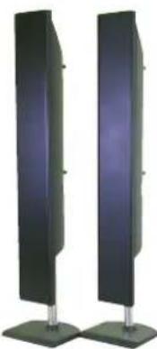
natural_image
Two vertical black-and-white panels with metallic legs, no text or symbols visible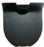

CAUTION: Install the covers in the base of the TV when the TV stand is removed to hang the TV on the wall.
Caring for Your TV

CAUTION: Only a licensed technician should service the TV. Do not disassemble the TV.

CAUTION: Before cleaning the TV, unplug it from the electrical outlet.
• To clean the surface of the panel, lightly dampen a soft, clean, lint-free cloth with water.
• To clean the TV cabinet, use a cloth lightly dampened with a mild detergent.
- Do not use chemicals such as benzene, thinner, ammonia, or any type of abrasive cleaner.
- Do not use compressed air to clean the TV.
Setting Up Your TV

CAUTION: Before you begin any of the setup procedures described in this section, follow the basic safety instructions located in the Product Information Guide.
Proper Location for Your TV
Consider the following environmental factors when you are deciding where to put your TV:
- Ensure you allow adequate ventilation.
- Do not store or use the TV in locations that are exposed to high heat, direct sunlight, or extreme cold.
- Avoid moving the TV between locations with extreme temperature differences. For more information, see "Specifications for Your TV" on page 41.
- Do not subject the TV to severe vibration or high impact conditions. Do not place the TV inside a car trunk.
- Do not store or use the TV in locations where the TV would be exposed to high humidity or dusty environment.
- Do not place the TV in a location where water or other liquids could spill on or into the TV.
Connecting Your TV
The tables below provide a description of the connectors on your TV to help you decide which connectors to use for your various video devices.
Connecting Your Cable TV Box or Antenna
Quality Cable and connector When to Use
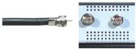
Good Coaxial cable
natural_image
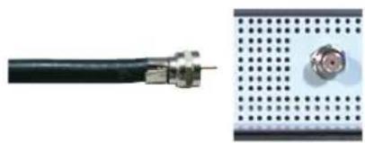
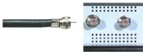
Close-up of a black cable with metallic connectors next to a perforated panel (no text or symbols visible)Coaxial (RF) cable carries the video and audio signal from the antenna or cable connector to your TV. The coaxial connector is labelled NTSC. To locate the NTSC connector see "Bottom View" on page 7.
Best Coaxial cable (for W4200HD only)
natural_image
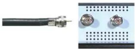
Close-up of a black cable with metallic connectors next to a grid-patterned device (no visible text or symbols)The ATSC cable carries the digital video and audio signal from the antenna connector to your TV. To locate the ATSC connector see "Bottom View" on page 7.
Connecting Your Video Devices
Quality Cable and connector When to Use
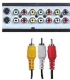
Good Composite
natural_image
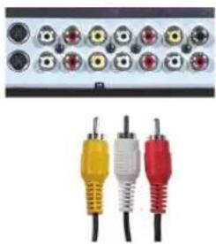
Close-up of three colored audio/video connectors (yellow, red, black) with black cables, no visible text or symbols.The composite connector carries the video signal through a single pin. If you are using a composite video connector, you also need to connect composite audio cables. To locate the composite connectors, see "Right View" on page 6 and "Bottom View" on page 7.
Quality Cable and connector When to Use
Better S-Video
natural_image
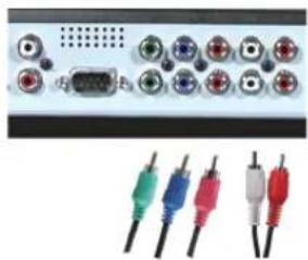
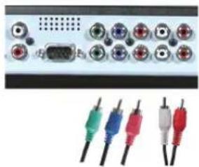
Close-up of three connected audio/video connectors (red, white, black) with no visible text or symbols on the connectors themselves.Best Component (YPbPr)
natural_image
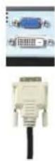
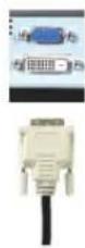
Front panel of a computer interface with multiple connected ports and colored cables (no visible text or labels)Excellent DVI
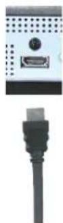
Excellent HDMI
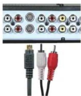
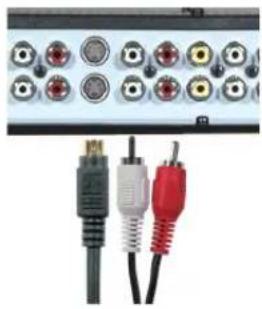
The S-Video connector splits the video signal into two signals, black-and-white and color. If you are using the S-Video connector, you also need to connect the audio cables. To locate the S-Video connectors, see "Right View" on page 6 and "Bottom View" on page 7.
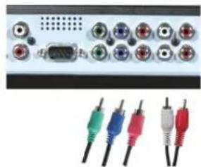
The component connectors splits the video signal into three signals, two color and one black-and-white. If you are using the component connectors, you also need to connect the audio cables. To locate the component connectors, see "Bottom View" on page 7.
DVI receives the image data in digital format so that the TV does not need to perform an analog-to-digital conversion, as with the input types described above. Because the TV uses digital data to display the image, DVI provides the highest quality input, although actual results depend on the video source (DVD player, DVR, etc.). To locate the connector see "Bottom View" on page 7.
HDMI (High Definition Multimedia Interface) assures that the best video signal is always sent from source (IIDTV signal, DVD player) to the TV. This is achieved by allowing uncompressed video and multi-channel audio data to be sent to the display device through a single cable. To locate the connector see "Bottom View" on page 7.
Using the ATSC or NTSC Connector (Coaxial)
natural_image
Close-up of a black cable with metallic connectors next to a grid-patterned device (no visible text or symbols)1 Turn off the TV and unplug the power cord.
2 Connect the coaxial cable to the ATSC or the NTSC connectors on the TV.
NOTE: ATSC connector is available only on W4200HD.
3 Plug in the power cord for the TV and turn on the TV.
4 Enter the OSD and select TV for NTSC or Digital TV for ATSC. See "Input Select" on page 26 for more information.
Using the Composite Connector
natural_image
Three colored audio/video connectors (yellow, red, black) connected to a black cable, with no visible text or symbols.1 Turn off the TV and unplug the power cord.
NOTE: If you are connecting a device that you want to be able to remove, such as a video game system or a camcorder, use the composite connector on the right side of the TV (see "Right View" on page 6).
2 Connect your device to the TV using the audio and video cable.
3 Plug in the power cords for the TV and devices and turn them on.
4 Enter the OSD and select AV5 or AV6. See "Input Select" on page 26 for more information.
Using the S-Video Connector
natural_image
Close-up of a black and red audio/video equipment with three connected cables (no visible text or symbols)1 Turn off the TV and unplug the power cord.
NOTE: If you are connecting a device that you want to be able to remove, such as a video game system, or a camera, use the S-Video connector on the right side of the TV (see "Right View" on page 6).
2 Connect your device using the S-Video and audio cables.
3 Plug in the power cords for the TV and devices and turn them on.
4 Enter the OSD and select AV3, AV4, or AV8 (side S-Video connector). See "Input Select" on page 26 for more information.
Using the Component Connector
natural_image
Front panel of a computer interface with multiple connected ports and colored cables (no visible text or labels)1 Turn off the TV and unplug the power cord.
2 Connect your device using the component video and audio cables.
3 Plug in the power cords for the TV and devices and turn them on.
4 Enter the OSD and select AV1 or AV2. See "Input Select" on page 26 for more information.
Using the HDMI Connector
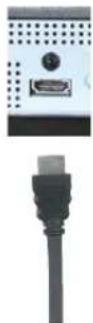
1 Turn off the TV and unplug the power cord.
2 Connect your device using the HDMI connector.
3 Plug in the power cords for the TV and devices and turn them on.
4 Enter the OSD and select HDMI. See "Input Select" on page 26 for more information.
Using the DVI Connector

NOTE: Only one connector can be used for a computer, either VGA or DVI.
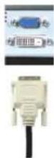
1 Turn off the TV and unplug the power cord.
2 Connect the white DVI cables and the audio cables.

NOTE: Some cable TV boxes may have DVI connectors, but do not support using a DVI connection. For more information, contact your cable TV company.
3 Plug in the power cords for the TV and devices and turn them on.
4 Enter the OSD and select DVI. See "Input Select" on page 26 for more information.
Using the VGA Connector

NOTE: Only one connector can be used for a computer, either VGA or DVI.
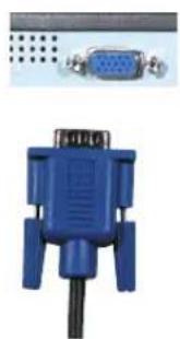
natural_image
Blue VD connector with 10-pin GND (no text or symbols visible)1 Turn off the TV and unplug the power cord.
2 Connect the VGA and audio cables to your TV and to your computer.
3 Plug in the power cords for the TV and devices and turn them on.
4 Enter the OSD and select VGA. See "Input Select" on page 26 for more information.
Image Retention and Burn-In

NOTE: Image retention and burn-in are not covered by your Dell warranty.
Displaying an image for an extended period of time can cause an image to remain or burn-in on the screen. Burn-in is a characteristic of all plasma displays.
To help avoid image burn-in, it is best to avoid leaving stationary images on your TV for extended periods of time. Examples of stationary images that may lead to burn-in include:
• TV menus
• TV channel logos
• Stock market or news tickers
- Time display
• Shopping channel pricing display
• Static computer images
• Static video game images
- Closed captioning backgrounds
- Black bars such as those used in 4:3 or wide screen mode
Your Remote Control
Installing Batteries
Before you can use your remote control, install two AAA batteries in the remote control as follows.
1 Open the battery cover.
2 Install the batteries. Make sure that you match the + and - on the batteries with the + and - symbols in the battery compartment.
3 Close the battery cover.
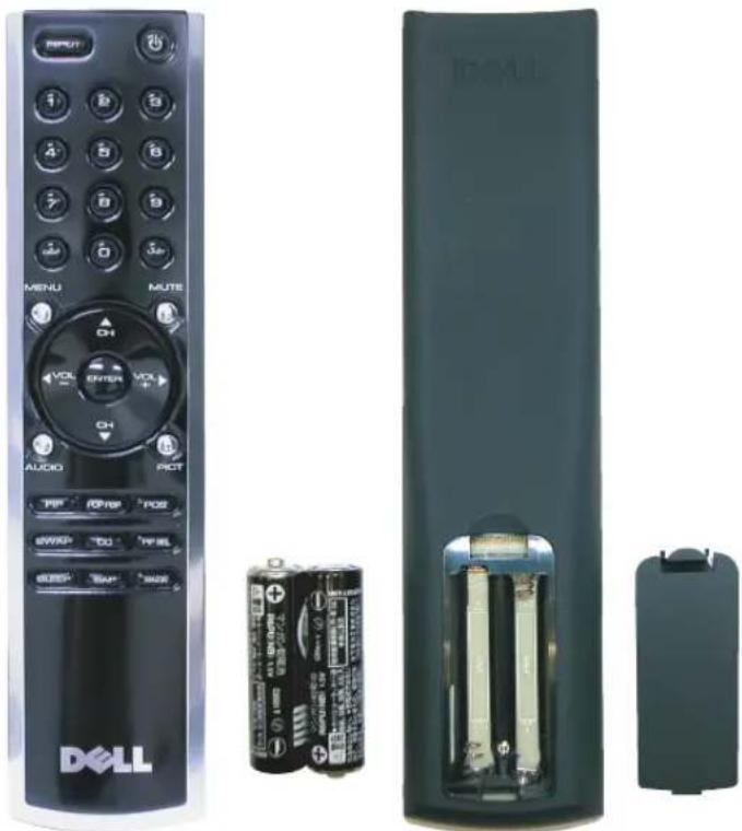
natural_image
Exterior view of a Dell remote control with visible buttons, battery pack, and rear panel (no text or symbols on main objects)Using Your Remote Control
W4200ED
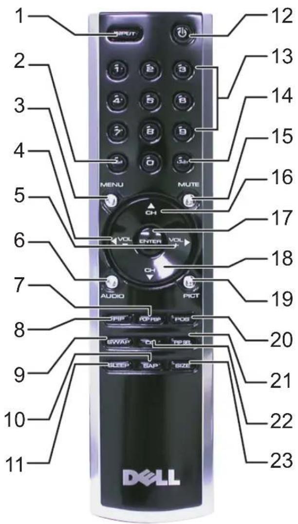
| 1 | INPUT | Enters the Input Select menu |
| 2 | DISP Displays information about your TV (for example, in TV mode, it displays the channel you are watching) | |
| 3 | MENU Enters and exits the OSD main menu | |
| 4 | Vol - Decreases the volumeIn the OSD menu, use the volume button to navigate through the menus | |
| 5 | Vol + Increases the volumeIn the OSD menu, use the volume button to navigate through the menus | |
| 6 | AUDIO | Cycles through the preset Audio options |
| 7 | POP PBP Enters and exits POP or PBP mode | |
| 8 | PIP Enters and exits PIP mode | |
| 9 | SWAP Swaps images when using PIP, POP, or PBP | |
| 10 | SAP | Turns on Second Audio Program (SAP) |
| 11 | SLEEP | Turns on the sleep timer |
| 12 | Power | Turns the TV on and off |
| 13 | Number buttons | Press to select a channel |
| 14 | LAST | Returns you to the previously viewed channel |
| 15 | MUTE | Press to turn the sound on and off |
| 16 | CII ▲ | Push to view the next channelIn the on-screen display (OSD) menu, use the channel button to navigate through the menus |
| 17 | ENTER | Press to confirm your selection |
| 18 | CII ▼ | Push to view the previous channelIn the OSD menu, use the channel button to navigate through the menus |
| 19 | PICT | Cycles through the preset options for the Picture menu |
| 20 | POS | Press to change the position of the PIP, POP, or PBP window |
| 21 | PIP SEL | Toggles between windows when you use Picture-in-Picture (PIP), Picture-Outside-Picture (POP), or Picture-By-Picture (PBP) |
| 22 | CC | Cycles through the Closed Caption menu |
| 23 | SIZE | Cycles through the size (aspect ratio) options from the Picture menu |
Using Your Remote Control
W4200HD
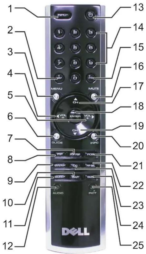
| 1 | INPUT | Enters the Input Select menu |
| 2 | DISP Displays information about your TV (for example, in TV mode, it displays the channel you are watching) | |
| 3 | MENU Enters and exits the OSD main menu | |
| 4 | Vol - Decreases the volumeIn the OSD menu, use the volume button to navigate through the menus | |
| 5 | Vol + Increases the volumeIn the OSD menu, use the volume button to navigate through the menus | |
| 6 | GUIDE (W4200HD only) | Displays an electronic program guide when using Digital TV (ATSC connector)NOTE: Content may vary depending on the broadcaster. |
| 7 | POP PBP Enters and exits POP or PBP mode | |
| 8 | PIP Enters and exits PIP mode | |
| 9 | SWAP Swaps images when using PIP, POP, or PBP | |
| 10 | SAP Turns on Second Audio Program (SAP) | |
| 11 | SLEEP | Turns on the sleep timer |
| 12 | AUDIO | Cycles through the preset Audio options |
| 13 | Power | Turns the TV on and off |
| 14 | Number buttons | Press to select a channel |
| 15 | LAST | Returns you to the previously viewed channel |
| 16 | MUTE | Press to turn the sound on and off |
| 17 | CH ▲ | Push to view the next channelIn the on-screen display (OSD) menu, use the channel button to navigate through the menus |
| 18 | ENTER | Press to confirm your selection |
| 19 | CH ▼ | Push to view the previous channelIn the OSD menu, use the channel button to navigate through the menus |
| 20 | INFO (W4200HD only) | Displays HDTV channel information |
| 21 | POS | Press to change the position of the PIP, POP, or PBP window |
| 22 | PIP SEL | Toggles between windows when you use Picture-in-Picture (PIP), Picture-Outside-Picture (POP), or Picture-By-Picture (PBP) |
| 23 | CC | Cycles through the Closed Caption menu |
| 24 | SIZE | Cycles through the size (aspect ratio) options from the Picture menu |
| 25 | PICT | Cycles through the preset options for the Picture menu |
Using Your TV With a Universal or Learning Remote Control
Preprogrammed universal remote controls can be programmed to control the following functions on your Dell TV:
• P o w c r
- Channel Up (+)
- Channel Down (-)
• Volume Up (+)
• Volume Down (-)
- Mute
- Input Select
NOTE: Future preprogrammed universal remote controls may be able to control more functions.
You can program universal remote controls to work with your Dell TV in the following ways:
- If the remote control manual lists codes by manufacturer, use the Phillips codes.
- If the remote control has a search function, this function may be used to find the correct code.
- If the remote control has a learning function, you can program specific buttons on it from the Dell remote control, in addition to those buttons listed above.
NOTE: See the remote control documentation for specific instructions for your universal or learning remote control.
Using the On-Screen Display
Your TV display has an on-screen display (OSD) that allows you to select the proper input source, make adjustments to the image and audio settings, select to view Picture-In-Picture, Picture-Outside-Picture, and Picture-By-Picture, and set parental controls.
Using Your Remote Control With the OSD

NOTE: You can access and make selections to the OSD using the volume and channel buttons on the side panel of the TV or you can use the remote control. Except where noted, this section describes how to use the OSD with the remote control.
1 To enter the OSD, press the Menu button.
Eight icons appear along the bottom of the screen.
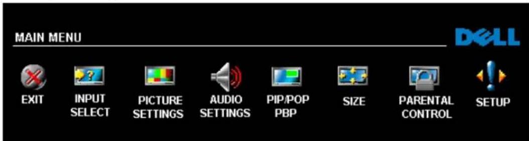
2 Use the left and right buttons (volume buttons) to move between the icons.
The icon appears highlighted as you move through the menu.
3 To select an option, push the Menu button when the icon is highlighted.
4 A new menu appears for that selected option. Use the up and down buttons (channel buttons) to move through the various settings.

NOTE: A red arrow appears next to the setting as you navigate through the options. A check mark appears next to the option that you have selected.
5 Use the left and right buttons (volume buttons) and the Enter button to adjust or select settings.

NOTE: You can select Exit or press the Menu button at any time to return to the main menu.
6 After you have made your selections, push the Menu button to return to the main menu.
7 To exit the OSD, select the EXIT icon and press Enter.
Selecting Your OSD Language
1 Press Menu to enter the OSD.
2 Select Setup.
3 In the Setup menu, select Language and scroll to select the language that you want the OSD to appear in.
Input Select
The Input Select menu allows you to select the proper source based on how you have your TV display and video equipment connected. Press Input on the remote to go directly to the Input Select menu. You can also pressMenu and select Input Select from the main menu.
If you are using the TV (NTSC connector) or the Digital TV (ATSC connector) input source, you can preset the viewable channels. Go to the Main Menu, select Setup, select Channel Setup, and then select Channel Search. If you have a W4200HD TV and you are using the NTSC connector and the ATSC connector, you need to preset the viewable channels for both the Digital TV and the TV input sources.
W4200ED W4200HD
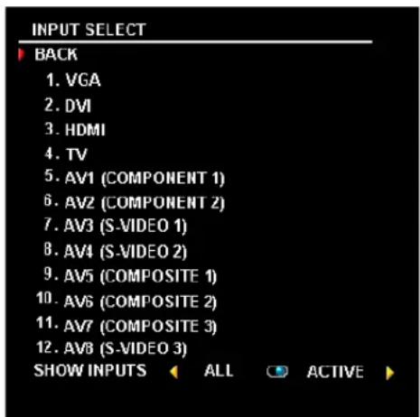
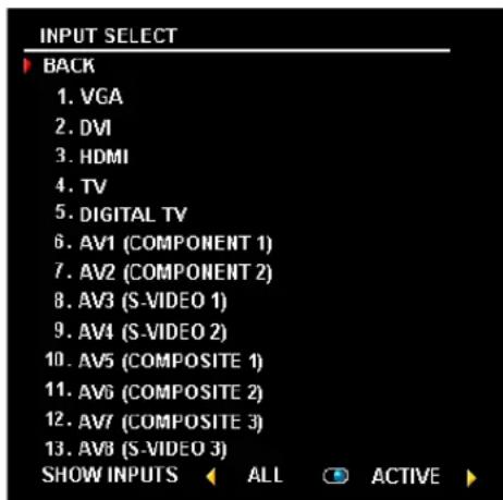
VGA — Select when you have your computer connected to the VGA connector. See "Bottom View" on page 7 for the location of the VGA connector.
DVI — Select when you have connected your computer or a device such as a DVD player to the DVI connector. See "Bottom View" on page 7 for the location of the DVI connector.
HDMI — Select when you have connected a device, such as a DVD player using the HDMI connector. See "Bottom View" on page 7 for the location of the HDMI connector.
TV — Select when you have your antenna or cable TV box connected to the NTSC connector. See "Bottom View" on page 7 for the location of the NTSC connector.
DIGITAL TV — Select when you have your antenna connected to the ATSC connector. See "Bottom View" on page 7 for the location of the ATSC connector. (for W4200IID only)
AV1 (COMPONENT 1) — Select when you have a video device, such as a DVD player, set-top box, or cable TV box, connected to the component audio and video connectors on the bottom of the TV. See "Bottom View" on page 7 for the location of the component audio and video connectors.
AV2 (COMPONENT 2) — Select when you have a video device, such as a DVD player, set-top box, or cable TV box, connected to the component audio and video connectors on the bottom of the TV. See "Bottom View" on page 7 for the location of the component audio and video connectors.
AV3 (S-VIDEO 1) — Select when you have a video device, such as a VCR, connected to the S-Video connector on the bottom of the TV display. See "Bottom View" on page 7 for the location of the S-Video connector.
AV4 (S-VIDEO 2) — Select when you have a video device, such as a VCR, connected to the S-Video connector on the bottom of the TV display. See "Bottom View" on page 7 for the location of the S-Video connector.
AV5 (COMPOSITE 1) — Select when you have a video device, such as a video game system, connected to the composite connector on the bottom of the TV display. See "Bottom View" on page 7 for the location of the composite video and audio connectors.
AV6 (COMPOSITE 2) — Select when you have a video device, such as a video game system, connected to the composite connector on the bottom of the TV display. See "Bottom View" on page 7 for the location of the composite video and audio connectors.
AV7 (COMPOSITE 3) — Select when you have a video device, such as a video game system, connected to the composite connector on the side of the TV display. See "Right View" on page 6 for the location of the composite connector.
AV8 (S-VIDEO 3) — Select when you have a video device, such as a VCR, connected to the S-Video connector on the side of the TV display. See "Right View" on page 6 for the location of the S-Video connector.
SHOW INPUTS — Show Inputs allows you to select Active or All. Active searches for which connectors are being used. The available input sources appear in white and input sources that are not available appear in grey. All shows all the input sources and allows you to select all the input sources even if you do not have a device connected.

NOTE: In OSD Settings, located in the Setup menu, you can set the Input Select to display the device that you have attached. For example, AV2 would say DVD when you view the Input Select menu.
Picture Menu
The Picture Menu allows you to adjust the appearance of the image including color and brightness.
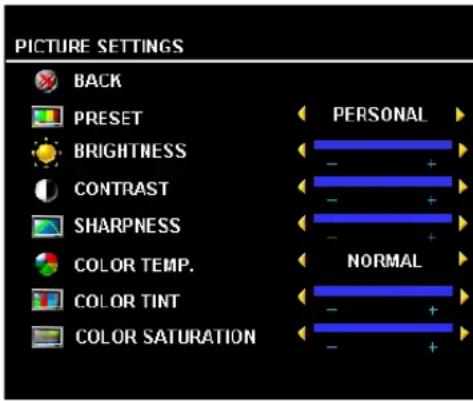
If you select one of the following preset image settings the individual settings are automatically updated.
- M o v i e s • Weak Signal - S p o r t s • Multimedia
If you select Personal, you can adjust the individual settings, such as Brightness and Color.
The color temperature presets are:
• Natural: 6500K
• Normal: the native panel temperature
- Blue: 9300K
• Red: 5700K
Audio
The Audio Menu allows you to set the audio to best fit the type of show you are watching.
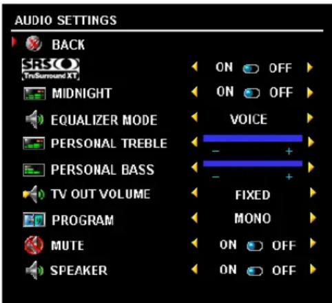
Midnight Mode — Evens out the large volume variations between voice and action scenes.
SRS TruSurround XT—Delivers virtual surround sound over two speakers from any source, which creates a wider sound with deep rich bass.
Speaker On/Off — Allows you turn on or off the sound from the speaker.
TV Out Volume — Select Fixed if you want to adjust the volume using the remote or volume control on an attached audio receiver. Select Variable if you want to adjust the volume using the TV remote or front panel buttons. Using Variable adjusts the TV volume out not the volume on an attached audio receiver
If you select one of the following preset Equalizer Mode settings, the individual audio levels are automatically updated:
- Music
- Theater
- Voice
If you select Personal, you can adjust the individual audio levels, such as Bass and Treble.
Use Program to select Stereo, Mono, or SAP (Second Audio Program).
PIP/POP/PBP
You can view two active sources simultaneously using Picture-In-Picture (PIP), Picture-Outside-Picture (POP), or Picture-By-Picture (PBP).
For POP, you can select from three different POP options:
- POP — One large POP window to the left and a smaller, centered window on the right.
- POP3 — One large POP window to the left and three smaller, vertically-aligned windows on the right.
- POP12 — One large, centered POP window surrounded by twelve smaller windows.
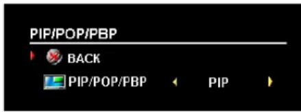
The remote control offers the following PIP/POP/PBP options:
- Use the PIP button or the POP PBP button on the remote control to turn on and off PIP, POP, and PBP.
- If you are in PIP, POP, or PBP mode, use the SWAP button on the remote control to switch between the two windows.
- Use the POS button on the remote to change which corner of the screen the PIP window appears.
In the OSD, you can adjust the Transparency, the Size, and II (horizontal) and V (vertical) position of the PIP/POP/PBP windows. When you are selecting the horizontal orientation, - moves the window left and + moves the window to the right. When you are adjusting the vertical orientation, 0 is at the top of the screen and 100 is at the bottom of the screen.
POP Scan Mode allows you to select Sequential or Float. Float mode plays the source for selected channels that appear in the windows. Sequential rotates through each window and plays all of the preselected channels. The rotation mode runs through all the available channels before it starts again at the lowest channel.
PIP/POP/PBP Compatibility
When using PIP/POP/PBP you can select any of the input sources that appear in the PIP/POP/PBP windows. The only input sources that cannot work together are HDMI with HDMI, DVI with DVI, and HDMI with DVI.
Size

NOTICE: Using black bars, such as those seen in Wide or 4:3, for an extended period of time may cause burn-in on your TV.
Size allows you to adjust the appearance of the image. Use H. Position and V. Position to adjust the horizontal and vertical placement of the image.
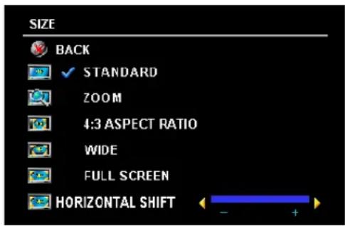
Use the following settings to adjust the aspect ratio:
Standard — Best selection for viewing digital HIDTV, 16:9 or 22:9 DVD movies.
Zoom — Best selection for viewing TV, VCR or 4:3 DVD movie.
4:3 — Best selection for viewing TV, VCR or 4:3 DVD movie.
Wide — Best selection for viewing digital HIDTV, 16:9 and 22:9 DVD movies.
Full Screen — Best selection for viewing digital HDTV or 16:9 DVD movies.
Horizontal Shift—Adjust the horizontal placement of the image.

NOTE: Most DVDs have information about the supported aspect ratio on the case.
Parental Control
Parental Control allows you to block certain channels or programs so children cannot view programs that are not age appropriate.
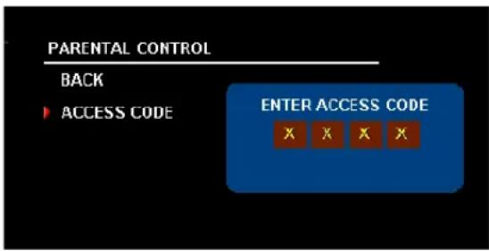
To enter the Parental Control menu, you need an access code. The first time you enter, use access code 3355. See "Setting an Access Code" on page 31 for information on creating a new access code.
You can set the following options to block content:
• Channel Lock — Blocks selected channels
• Movie Rating — Blocks movies based on their rating (G, PG, PG-13, R, NC-17, and X)
• TV Ratings — Blocks TV shows based on their rating
• Block Options — Turns on or off all your parental control settings

NOTE: You can use Clear All to unblock the channels and programs that you have set.
Setting an Access Code
After you enter the Parental Controlmenu for the first time, you can set your own four-digit access code. If for any reason you lose or forget your access code, you can use the default code.
1 In the Parental Control menu, select Change Code.
2 Using the number pad on the remote control, enter a new access code.
3 Select Exit.
Setup
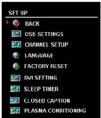
Setup allows you to adjust the appearance of the OSD, preset viewable cable channels, change the language of the OSD (see "Selecting Your OSD Language" on page 26) and to restore factory settings.
In the OSD Settings menu, use OSD Hold Time to increase or decrease the amount of time the OSD appears. The maximum amount of time is 60 seconds. You can select TV Button Lock to lock the buttons on the bottom panel. When this option is enabled, only the power button functions. Hold the volume increase and the channel increase buttons together for 10 seconds to unlock the buttons.
Channel Setup allows you adjust the settings for individual channels and preset the viewable channels. If you are using the TV (NTSC connector) or the Digital TV (ATSC connector) input source, you can preset the viewable channels. Go to the Main Menu, select Setup, select Channel Setup, and then select Channel Search.
If you have a W4200HD TV and you are using the NTSC connector and the ATSC connector, you need to preset the viewable channels for both the Digital TV and the TV input source.
DVI Settings allows you to change the color space. The default color space is RGB, but if the colors are not displaying correctly, you can change the setting to YUV.
Sleep Timer allows you to set an increment of time after which the TV automatically turns off.
Select Closed Caption to turn on and off closed captioning and set several other CC options.
If an image appears to be stuck on the TV, select Plasma Conditioning to help eliminate any image retention. Using the plasma conditioning feature may take several hours. Severe cases of image retention are known as burn-in, the plasma conditioning feature does not remove burn-in.
Use plasma conditioning only when you experience a problem with image retention. Overuse may degrade the TV brightness.
Troubleshooting Problems With Your TV

CAUTION: If at any time you see smoke or sparks coming from your TV, contact Dell. Do not try to perform any troubleshooting steps.
Troubleshooting Tips

NOTE: Some problems may be related to your device. See the documentation for any devices connected to your TV display.
Most problems with your TV may be caused by not having the correct input selection. Each connector on the TV (side and bottom) is associated with an input selection, which are labelled AV1 through AV8 in the Input Select menu.
- AV1 — Component connector on the bottom of the TV
- AV2 — Component connector on the bottom of the TV
- AV3 — S-Video connector on the bottom of the TV
• AV4 — S-Video connector on the bottom of the TV - AV5 — Composite connector on the bottom of the TV
- AV6 — Composite connector on the bottom of the TV
• AV7 — Composite connector on the right of the TV
• AV8 — S-Video connector on the right of the TV
You can also select the following inputs:
• TV — NTSC connector on the bottom of the TV
• DIGITAL TV — ATSC connector on the bottom of the TV
• VGA — VGA connector on the bottom of the TV
• DVI — DVI connector on the bottom of the TV
General Problems
Problem Possible Solution
Poor picture quality while watching TV and using a device such as a DVD player or a VCR
1 Check the aspect ratio settings in the OSD. Press the Menu button on the remote control and select Size. For more information on using the OSD, see "Using the On-Screen Display" on page 25.
2 Reconnect the device using the same type of connector. For example, if you are using the composite connector on the bottom, try connecting the device to the composite connector on the side of the TV display. See "About Your TV" on page 5 for the location of the connectors. After you connect the device, change the input source in the OSD. See "Input Select" on page 26 for more information.
3 Connect the device using a different connector. For example, if you are experiencing the problem using a composite connector, try using the component connector.
NOTE: To connect to a different connector, you need the appropriate cables for that connector. See your device documentation for a list of supported connections.
After you connect the device, change the input source in the OSD. See "Input Select" on page 26 for more information.
4 Reset the original factory defaults. Press Menu on the remote control, select Setup, and then select Factory Reset.
5 Adjust the color temperature. Press Menu on the remote control, select Picture, and then select Color Temperature.
NOTE: Some set top boxes offer aspect ratio. See your device documentation for more information.
Poor picture quality when using a device connected to the ANT/Cable (coaxial) connector
1 Ensure TV display is selected as the input source in the Input Source menu. See "Input Select" on page 26 for more information.
2 Press Menu on the remote control, select Setup, and then select Channel Setup. This resets the channels on your TV.
3 Check the aspect ratio settings in the OSD. Press the Menu button on the remote control and select Size. For more information on using the OSD, see "Using the On-Screen Display" on page 25.
4 Reset the original factory defaults. Press Menu on the remote control, select Setup, and then select Factory Reset.
5 Adjust the color temperature. Press Menu on the remote control, select Picture, and then select Color Temperature.
6 The problem may be with your device, contact your service provider.
Problem Possible Solution
Nothing appears on my TV display 1
Ensure the TV display is turned on.
2 Verify that all the cables are properly connected to the TV display, including the power cable.
3 Check to see if there is a blue or amber light on the lower, right-hand corner of the TV display. A blue light indicates the TV display is on. An amber light, means the TV display is in power save mode.
4 Ensure the proper source is selected in the Input Source menu. See "Input Select" on page 26 for more information.
5 Reconnect any devices that are currently connected to the TV display. If you are using multiple devices, connect and test one device at a time.
6 Connect another device that you know is working properly.
7 Reset the original factory defaults. Press Menu on the remote control, select Setup, and then select Factory Reset.
Problem Possible Solution
| No sound 1 | Ensure mute is not turned on. Pressing the Mute button on the remote control turns the mute function on and off.2 If only certain TV channels do not have sound, then you need to correct the Input Select menu in the OSD (see "Input Select" on page 26).3 Verify that the audio cables are firmly connected to both the audio input connectors on your TV display and audio output connectors on your devices. Ensure that the cable colors match the connectors colors.4 Also, ensure that the audio cables are connected to the same row as the video cables. See "About Your TV" on page 5 for the location of the connectors.5 Reconnect the device using the same type of connector. For example, if you are using the composite connector on the bottom, try connecting the device to the composite connector on the side of the TV display. See "About Your TV" on page 5 for the location of the connectors.After you connect the device, change the input source in the OSD. See "Input Select" on page 26 for more information.6 Connect the device using a different connector. For example, if you are experiencing the problem using a composite connector, try using the component connector.NOTE: To connect to a different connector, you need the appropriate cables for that connector. See your device documentation for a list of supported connections.After you connect the device, change the input source in the OSD.See "Input Select" on page 26 for more information.7 Test the device on a different TV.8 If you are using PIP/POP/PBP, ensure the proper Audio Source is selected. Press Menu on your remote control, and select PIP/POP/PBP. |
| Double image or no image with DVD | Turn off the progressive scan on the DVD player. Your DellTM TV display offers built-in deinterlacer that is equal to or better quality than the deinterlacer on your DVD player. For more information about progressive scan on your DVD player, see the documentation for your DVD playerPixel defects within industry specifications are inherent to an PDP TV and do not constitute a defective problem. For more information about pixels and PDP technology, go to support.dell.com. |
| Picture is too dim or too bright | Update the color settings in the OSD. Press Menu on the remote control and select Picture. |
Problem Possible Solution
| The screen is not centered correctly 1 | Update the size settings in the OSD. Press Menu on the remote control and select Size. |
| 2 Reset the original factory defaults. Press Menu on the remote control, select Setup, and then select Factory Reset. | |
| Screen has one or more lines 1 | Check the aspect ratio settings in the OSD. Press the Menu button on the remote control and select Size. For more information on using the OSD, see "Using the On-Screen Display" on page 25. |
| 2 Ensure the proper source is selected in the Input Source menu. See "Input Select" on page 26 for more information. | |
| 3 Try connecting a different device. Ensure that you properly connect the cables and update the input source in the OSD. | |
| 4 Update the size settings in the OSD. Press Menu on the remote control and select Size. | |
| 5 Reset the original factory defaults. Press Menu on the remote control, select Setup, and then select Factory Reset. | |
| The front panel buttons do not work | Check the OSD to see if the buttons have been locked. Press Menu on your remote control, select Setup. |
| If you are unable to use the remote control, press the volume up and the channel up buttons on the bottom of the TV display for 10 seconds to unlock the buttons. | |
| The picture is too small 1 | Adjust the size settings. Press Menu on the remote control, and select Size. |
| 2 This may be a problem with your device. See the documentation for the device. | |
| An image appears to be stuck on the TV. | In OSD Setup select Plasma Conditioning. Using this option may take several hours before the image is eliminated. |
| NOTE: Burn-in is not covered by your Dell warranty. |
OSD Messages
While using your TV display, the following messages may appear.
| Message Possible Solution | |
| Auto Adjust No action required, the TV display is performing an auto adjustment. | |
| Out of Range Check the optimal resolution settings. | |
| You may need to download a new video driver. For more information, go to support.dell.com. | |
| No Video Input | 1 Check all cables are properly connected.2 Ensure the proper source is selected. See "Input Select" on page 26 for more information. |
| TV Button Lock To unlock, press Menu on your remote control, select Setup. | |
| Self Test | Appears for computer source when there is nothing plugged in.Select VGA or DVI from Input Select menu and nothing is plugged in. Plug a computer in to the VGA or DVI connector. |
Remote Control Problems
| Problem Possible Solution | |
| The TV display does not respond when using the remote control | 1 Point the remote control directly at the lower right corner of the TV display. Be sure that nothing is blocking the front of the TV display. For the location of the IR, see "Front View" on page 5.2 Verify that the batteries are properly installed.3 If the batteries are old, install new batteries.NOTE: Bright lights or other infrared devices may interfere with your remote control and IR on the TV display. |
Using the Self-Test Feature when Connected to a Computer
When your computer is connected to the TV display through DVI or VGA connector you can use the self-test feature to check whether your TV display is functioning properly. If your TV display and computer are properly connected but the TV display screen remains dark, run the TV display self-test by performing the following steps:
1 Turn off both your computer and the TV display.
2 Unplug the video cable from the back of the computer.
3 Turn on the TV display. If the TV display cannot sense a video signal and is working correctly, the floating "Self-Test Feature Check" dialog box appears on the screen (against a black background). While in self-test mode, the power light remains blue and the self-test pattern scrolls through the screen continually. This box also appears during normal system operation if the video cable becomes disconnected or damaged.
4 Turn off your TV display and reconnect the video cable; then turn on both your computer and the TV display. If your TV display screen remains blank, the problem may be with your computer or graphic card.
See your computer documentation for more information.
Problems When Using the TV Display as a Monitor
Problem Possible Solution
| The picture is off-centered or too small | 1 Use Auto Adjust to check the Image Settings. Press Menu to enter the OSD, select Image Settings, and then select Auto Adjust.2 Check the optimal resolution settings. You may need to download a new video driver. For more information, go to support.dell.com.NOTE: Some older video cards may not support the resolution settings for the TV display. |
| No audio | 1 Ensure the green audio cable is connected to audio connector on the TV display and on the computer. For the location of the connector on the TV display, see "Using the VGA Connector" on page 17. See your computer documentation for the location of connectors on your computer.Do not connect the audio cable to the headphone jack.2 Ensure the volume on the computer is not muted.3 Verify that sound on your computer is working by checking the speakers. See your computer documentation for information on troubleshooting your computer.4 Disconnect the TV display from the computer and test to see if the TV display volume works. |
| Problem Possible Solution | |
| PIP/POP/PBP not working 1 | Ensure the settings in the OSD are properly set. Press Menu to enter the OSD, and select PIP/POP/PBP.2 Swap the video and audio source. |
| No video | NOTE: If you see a self-test, it means there is a problem with your video card or you are using the wrong input source.1 Ensure the TV display is turned on.2 Verify that all the cables are properly connected to the TV display, including the power cable.3 Check to see if there is a blue or amber light on the lower, right-hand corner of the TV display. A blue light indicates the TV display is on. An amber light, means the TV display is in power save mode.4 Ensure proper source is selected. See "Input Select" on page 26 for more information.5 Reconnect the computer.6 Connect another device that you know is working properly.7 Reset the original factory defaults. Press Menu on the remote control, select Setup, and then select Factory Reset. |
Specifications for Your TV
General
Model number W4200 PDP TV
Display type IID PDP panel (W4200IID)
ED PDP panel (W4200ED)
Screen size 42-inches
Viewable area 932 x 532 mm (36.7 x 20.9 inches)
Image aspect ratio 16:9 (wide screen)
Vidco display capabilities 480i
480p
576i
576p
720p
1080i
Additional features:
SAP capable Yes
CC capable Yes
Parental control capable Yes
Physical Dimensions
Display (with stand) 1031.8 x 712.5 x 245.7 mm
Display (no stand) 1031.8 x 631.5 x 83.8 mm
With Speakers
Weight (with stand) 46 kg/101.41 lbs (est.)
Native Resolution 1024 x 768 XGA (W4200HD)
852 x 480 WVGA (W4200ED)
HDTV Capable
Yes
Picture-In-Picture
| Picture-In-Picture (PIP) Yes | |
| Picture-Outside-Picture (POP) Yes | |
| Picture-By-Picture (PBP) Yes | |
| Number of Tuners 2 | |
| Brightness (typical) | |
| ED version | 450 nits (typ.) |
| HD version | 420 nits (typ.) |
| Contrast Ratio | |
| ED version | 2700: 1 (typ.) |
| IID version | 2300: 1 (typ.) |
Viewing Angle
| Horizontal +/-80 degree |
| Vertical +/-80 degree |
Inputs
| Video | |
| Composite (CVBS) | three in total (side and bottom) |
| S-Video | three in total (side and bottom) |
| Component | two (bottom) |
| TV In (coaxial) | two (bottom) (HD version x 2, ED version x 1) |
| Audio (RCA I.+R) | eight pairs in total (side and bottom) |
| DVI | one (bottom) |
| HDMI | one (bottom) |
| Computer | |
| VGA (for use as computer monitor) | one (bottom) |
| Audio (PC) | one (bottom) |
| Other | |
| RS232 | one (bottom) |
Outputs
Video
Outputs
| Composite (CVBS) | one (bottom) |
| Audio (RCA I.+R) | one pair (bottom) |
| Subwoofer | one |
| SPDIF (RCA + Optical) | one (HD model only) |
Audio
| Effects SRS TruSurround XT | |
| Midnight Mode | |
| Speakers (separate) 20 watts/channel | 40 watts total |
Index
A
about
package contents, 9
TV, 5
access code
default, 30
parental control, 30
setting, 31
ATSC, 31
cable, usage, 12
connecting, 14
connector, location, 8
audio
button, 21-23
connector for VGA, location, 7
connectors, location, 6
DVI connectors, location, 7
equalizer mode, 28
midnight mode, 28
OSD menu, 28
program, 28
speaker on/off, 28
SRS TruSurround, 28
TV out volume, 28
AV1/AV2. See component.
AV3/AV4. See S-Video.
AV5/AV6. See composite.
B
block
parental control, 30
button
audio, 21-23
CC, 21-23
channel up/down, 5
DISP, 21-23
enter, 21-23
guide (W4200HD), 23
INFO (W4200HD), 23
input, 21-23
input source, 5
last, 21-23
menu, 21-23
mutc, 21-23
OSD menu, 5
PICT, 21-23
PIP, 21-23
PIP SEL, 21-23
POP/PBP, 21-23
POS, 21-23
power, 5
SAP, 21-23
size, 21-23
sleep, 21-23
swap, 21-23
volume up/down, 5
C
CC
button, 21-23
channel
setup, 26, 31
channel lock
parental control, 30
coaxial
ATSC connector, 14
cable, usage, 12
digital audio out connector, location, 8
NTSC connector, 14
color temperature, 28
component
AV1/AV2 connectors, location, 7
cable, usage, 13
connecting, 15
composite
AV5/AV6 connectors, location, 7
cable, usage, 12
connecting, 14
video/audio out connectors, location, 8
composite video
connector, location, 6
computer
connecting, 17
connector
ATSC, 8
audio left/right, 6
coaxial digital audio out, 8
component (AV1/AV2), 7
composite (AV5/AV6), 7
composite video, location, 6
composite video/audio out, 8 DVI, 7
DVI audio connectors, 7
HDMI, 7
NTSC, 8
optical digital out, location, 8
power, 8
speaker out, 8
subwoofer, 8
S-Video, 6-7
VGA, 7
VGA audio, 7
G
guide
button (W4200HD), 23
H
IIDMI
cable, usage, 13
connecting, 16
connector, location, 7
button, 21-23
N
NTSC, 31
connecting, 14
connector, location, 8
0
optical digital out
connector, location, 8
OSD
audio menu, 28
hold time, 31
messages, 38
parental control menu, 30
picture menu, 28
PIP/POP/PBP, 29
setup menu, 31
size menu, 30
D
DISP
button, 21-23
DVI
audio connectors, location, 7
cable, usage, 13
connecting, 16
connector, location, 7
|
INFO
button (W4200ED), 23
input
button, 21-23
IR receiver
location, 5
E
enter
button, 21-23
equalizer mode, 28
music, 28
thcater, 28
voice, 28
F
float
POP scan mode, 29
L
last
button, 21-23
M
mcnu
button, 21-23
midnight mode, 28
mono, 28
movie rating
parental control, 30
mute
P
parental control, 30
about, 30
block options, 30
channel lock, 30
movie rating, 30
PICT
button, 21-23
picture by picture. See
PIP/POP/PBP
picture in picture. See
PIP/POP/PBP
picture menu
color temperature, 28
movies, 28
multimedia, 28
sports, 28
weak signal, 28
picture on picture. See PIP/POP/PBP
PIP
button, 21-23
PIP SEL
button, 21-23
PIP/POP/PBP
compatibility, 29
setting up, 29
plasma conditioning, 31, 37
POP/PBP
button, 21-23
POS
button, 21-23
power
connector, location, 8
power LED
location, 5
R
remote control
audio button, 21-23
CC button, 21-23
DISP button, 21-23
enter button, 21-23
guide button (W4200HD), 23
INFO button (W4200HD), 23
input button, 21-23
installing batteries, 19
last button, 21-23
menu button, 21-23
mute button, 21-23
PICT button, 21-23
PIP button, 21-23
PIP SEL button, 21-23
POP/PBP button, 21-23
POS button, 21-23
SAP button, 21-23
size button, 21-23
sleep button, 21-23
swap button, 21-23
troubleshooting, 38
universal, using, 24
W4200ED, using, 20
W4200IID, using, 22
s
SAP, 28
button, 21-23
second audio program. See SAP
self-test
using, 39
Sequential, 29
sequential
POP scan mode, 29
setup
channel setup, 31
channels, 31
DVI settings, 31
menu, 31
OSD hold time, 31
size
4 to 3, 30
button, 21-23
full screen, 30
mcnu, 30
PIP/POP/PBP window, 29
standard, 30
wide, 30
zoom, 30
sleep
button, 21-23
SPDIF. See optical digital out
speaker out
connectors, location, 8
specifications, 41
audio, 43
general, 41
inputs, 42
outputs, 42
physical dimensions, 41
picture-in-picture (PIP), 42
viewing angle, 42
SRS TruSurround XT, 28
stereo, 28
subwoofer
connector, location, 8
S-Video
AV3/AV4 connectors, location, 7
cable, usage, 13
connecting, 15
connector, location, 6
swap
button, 21-23
T
tips
troubleshooting, 33
transparency
of PIP/POP/PBP window, 29
troubleshooting, 33
general problems, 34
OSD messages, 38
remote control, 38
self-test, 39
tips, 33
VGA monitor, 39
TV
about, 5
bottom view, 7
caring for, 10
front view, 5
proper location, 11
right view, 6
setting up, 11
troubleshooting, 33
TV ratings, 30
parental control, 30
V
VGA
connecting, 17
connector, location, 7
volume
fixed, 28
variable, 28
W
W4200HD
ATSC, 8
coaxial digital audio out, 8
optical digital out, 8
weak signal, 28
Dell™ W4200HD et W4200ED
natural_image
Exterior view of a Dell remote control device (no visible text or symbols on the device body)

Support mural (en option)
Haut-parleurs
natural_image
Metallic rectangular frame with two vertical supports and a central horizontal bar (no text or symbols visible)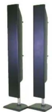
natural_image
Two vertical black-and-white panels with metallic legs, no visible text or symbols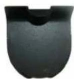

natural_image
Close-up of a black cable with metallic connectors next to a perforated metal plate (no text or symbols visible)natural_image
Close-up of a black coaxial cable with two metallic connectors, next to a grid-patterned electronic device (no visible text or symbols)natural_image
Close-up of a black and three-colored audio jack (yellow, red, gray) with no visible text or symbols on the connectors.natural_image
Close-up of three audio/video connectors (red, black, and white) connected to a black rectangular panel with multiple circular connectors (no text or symbols visible)natural_image
Front panel of a computer interface with multiple connected ports and colored cables (no visible text or labels)natural_image
Close-up of a black cable with metallic connectors next to a perforated electronic device (no visible text or symbols)natural_image
Close-up of a black audio/video audio jack with three colored cables (yellow, red, gray) attached to the right panel (no text or symbols visible)natural_image
Close-up of three connected audio/video cables (black, white, red) showing various connectors and audio units (no text or symbols visible)natural_image
Front panel of a computer interface with multiple connected ports and colored cables (no visible text or labels)natural_image
Blue VD connector with a 12-pin D-sub and two gold pins, shown against a white background (no text or symbols visible)natural_image
Exterior view of a Dell remote control with visible buttons, battery pack, and rear panel (no text or symbols on main objects)DISP (affichage) bouton, 69-71
picture by picture. Voir
PIP/POP/PBP
picture in picture
picture on picture. Voir
PIP/POP/PBP
PIP
bouton, 69-71
PIP SEL
bouton, 69-71
PIP/POP/PBP
compatibilité, 78
configuration, 77
POP/PBP
bouton, 69-71
POS
bouton, 69-71
présentation
bouton INFO (W4200HD), 71
bouton last (dernier), 69-71
bouton Mcnu, 69-71
bouton PICT (image), 69-71
bouton PIP, 69-71
bouton PIP SEL, 69-71
bouton POP/PBP, 69-71
bouton POS, 69-71
bouton SAP (seconde piste sonore), 69-71
bouton Swap (Permutation), 69-71
natural_image
Close-up of a stylized remote control device with visible keypad and control buttons (no text or symbols)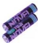

natural_image
Metallic rectangular frame with flanged supports and central slot (no text or symbols visible)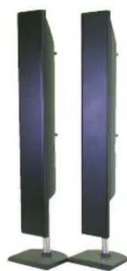
natural_image
Two vertical black panels mounted on metal bases, no text or symbols visible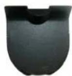

natural_image
Close-up of a black cable with metallic connectors next to a perforated panel (no text or symbols visible)Superior Cable coaxial (sólo para W+200HD)
natural_image
Close-up of a black coaxial cable with two metallic connectors, next to a perforated breadboard (no text or symbols visible)natural_image
Close-up of a black audio jack with three colored cables (yellow, red, gray) attached to a white panel (no text or symbols visible)natural_image
Close-up of three audio/video connectors (black, white, red) attached to a black rectangular panel with multiple circular buttons and connectors (no text or symbols visible)Superior Componente (YPbPr)
natural_image
Front panel of a computer interface with multiple connected ports and three colored cables (no visible text or labels)Excelente DVI
Excelente HDMI
natural_image
Close-up of a black cable with metallic connectors next to a grid-patterned electronic device (no visible text or symbols)natural_image
Close-up of three colored audio/video connectors (yellow, red, black) attached to a black rectangular panel (no text or symbols visible)natural_image
Close-up of three connected audio/video cables (black, white, red) showing various connectors and audio units (no text or symbols visible)natural_image
Front panel of a computer interface with multiple connected ports and colored cables (no visible text or labels)natural_image
Blue VD connector with 10-pin GND (no text or symbols visible)natural_image
Exterior view of a Dell remote control with visible buttons, battery pack, and rear panel (no text or symbols on main objects)SRS TruSurround, 126
SRS TruSurround XT, 126
subwoofer
- Notes, Notices, and Cautions
- Contents
- About Your TV
- Setting Up Your TV
- Your Remote Control
- Using the On-Screen Display
- Troubleshooting Problems With Your TV
- Specifications for Your TV
- About Your TV
- Front View
- Right View
- Package Contents
- Caring for Your TV
- Setting Up Your TV
- Proper Location for Your TV
- Connecting Your TV
- Connecting Your Cable TV Box or Antenna
- Quality Cable and connector When to Use
- Connecting Your Video Devices
- Using the ATSC or NTSC Connector (Coaxial)
- Using the Composite Connector
- Using the S-Video Connector
- Using the Component Connector
- Using the HDMI Connector
- Using the DVI Connector
- Using the VGA Connector
- Image Retention and Burn-In
- Your Remote Control
- Installing Batteries
- Using Your Remote Control
- Using Your TV With a Universal or Learning Remote Control
- Using the On-Screen Display
- Using Your Remote Control With the OSD
- Selecting Your OSD Language
- Input Select
- Picture Menu
- Audio
- PIP/POP/PBP
- PIP/POP/PBP Compatibility
- Size
- Parental Control
- Setting an Access Code
- Setup
- Troubleshooting Problems With Your TV
- Troubleshooting Tips
- General Problems
- Problem Possible Solution
- OSD Messages
- Remote Control Problems
- Using the Self-Test Feature when Connected to a Computer
- Problems When Using the TV Display as a Monitor
- Specifications for Your TV
- General
- Physical Dimensions
- Outputs
- Index
- A
- B
- C
- G
- H
- N
- 0
- D
- |
- E
- F
- L
- M
- P
- R
- s
- T
- V
- W
Brand : DELL
Model : W4200
Category : Home Theater System