
ELVOX 170F - Electrical relay Vimar - Free user manual and instructions
Find the device manual for free ELVOX 170F Vimar in PDF.
| Brand | Vimar |
| Model | ELVOX 170F |
| Product type | Programmable electrical relay |
| Power supply | +12 V DC (terminal 5) |
| Number of outputs | 4 (2 power relays, 2 open collector) |
| Output types | Outputs 1 and 2: open collector; Outputs 3 and 4: power relays |
| Programming | Via Dip Switch and buttons P1, P2, RES |
| Programmable parameters | Activation time (1 to 9999 s), initial/final user, device number |
| Operating modes | Command only, Number and command, Reset turn-off, Window activation, On/Off, Mutual exclusion |
| Compatibility | Digibus, Digit 2 Video, digital intercom systems (6221, 6935/A) |
| Connection | Digital terminals 1 and 6, ground 4, +12 V DC terminal 5 |
| PC interface | Via serial interface 6952 or USB 6952/A, PC software Digibus Analyzer |
| LED indicators | S1, S2, A, B for programming status |
| Operating temperature | -10 °C to +50 °C (estimated) |
| Protection rating | IP20 (estimated) |
| Housing material | ABS plastic (estimated) |
| Dimensions | Approximately 90 x 70 x 60 mm (estimated) |
| Weight | Approximately 150 g (estimated) |
| Maintenance | Disconnect before cleaning; do not obstruct ventilation slots |
| Safety | Bipolar switch required; repair by authorized center |
| Disposal | Selective collection (WEEE) – do not dispose of with household waste |
| Documents | User manual available as free PDF at notice-facile.com |
| Included accessories | No accessories provided |
Frequently Asked Questions - ELVOX 170F Vimar
User questions about ELVOX 170F Vimar
0 question about this device. Answer the ones you know or ask your own.
Ask a new question about this device
Download the instructions for your Electrical relay in PDF format for free! Find your manual ELVOX 170F - Vimar and take your electronic device back in hand. On this page are published all the documents necessary for the use of your device. ELVOX 170F by Vimar.
USER MANUAL ELVOX 170F Vimar
Communicating in style
RELÈ DIGITALE
DIGITAL RELAY
RELAIS DIGITAL
DIGITALRELAIS
RELÉ DIGITAL
RELÉ DIGITAL
natural_image
Isometric line drawing of a mechanical component with internal slots and mounting base (no text or symbols)I
| Funzionamento Attivazione Dip | 1 Dip 2 Dip 3 Dip 4 | |||
| Solo comando OFF --- --- | ||||
| Numero e comando ON --- --- --- | ||||
| Spegnimento con reset --- ON --- | --- | |||
| Attivazione a finestra OFF --- ON | --- | |||
| Funzionamento On / Off --- --- --- | ON | |||
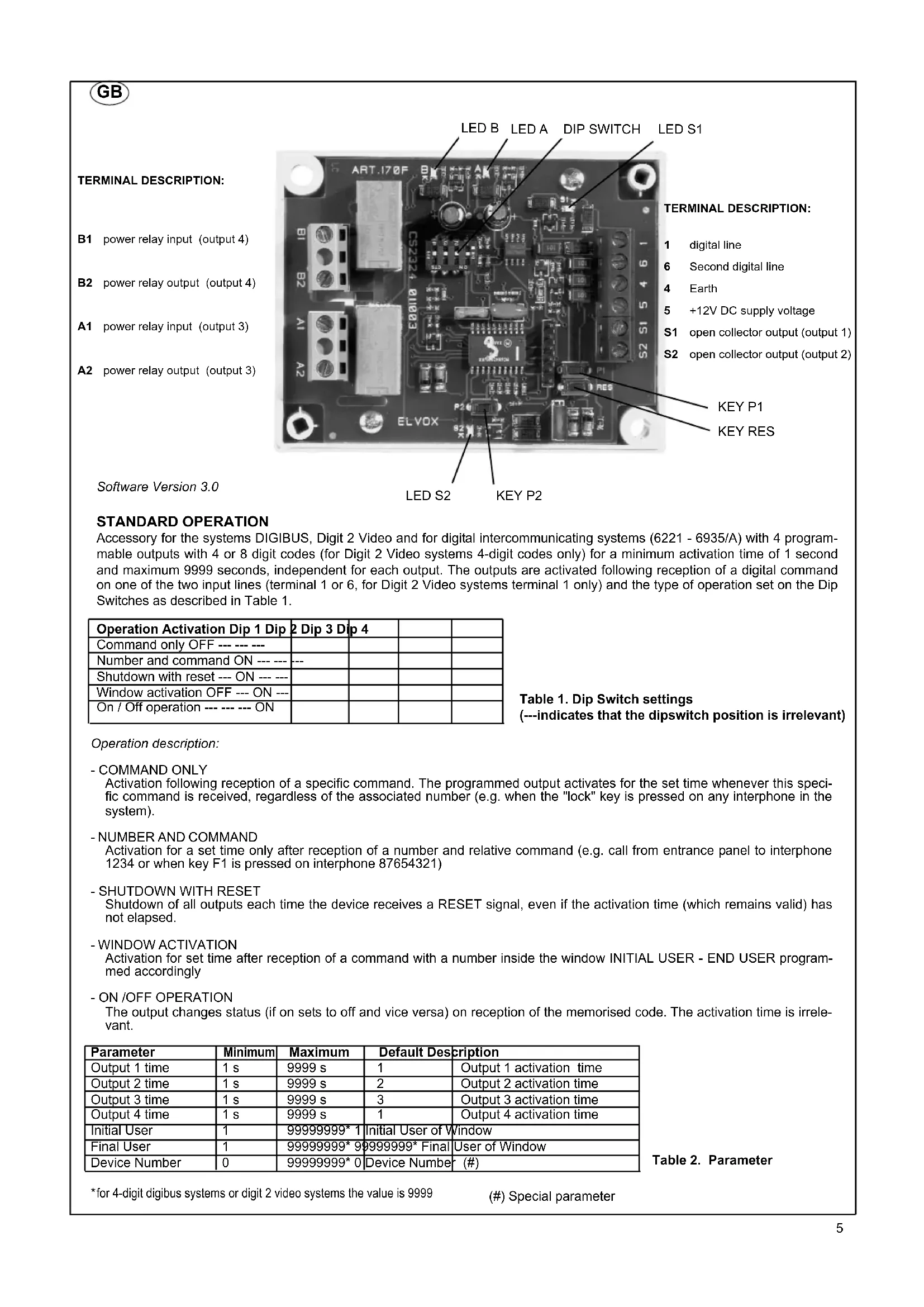
B1 power relay input (output 4)
B2 power relay output (output 4)
A1 power relay input (output 3)
A2 power relay output (output 3)
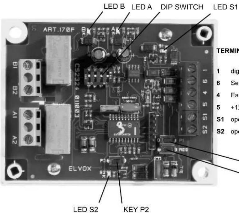
TERMINAL DESCRIPTION:
1 digital line
6 Second digital line
4 Earth
5 +12V DC supply voltage
S1 open collector output (output 1)
S2 open collector output (output 2)
KEY P1
KEY RES
Software Version 3.0
STANDARD OPERATION
Accessory for the systems DIGIBUS, Digit 2 Video and for digital intercommunicating systems (6221 - 6935/A) with 4 programmable outputs with 4 or 8 digit codes (for Digit 2 Video systems 4-digit codes only) for a minimum activation time of 1 second and maximum 9999 seconds, independent for each output. The outputs are activated following reception of a digital command on one of the two input lines (terminal 1 or 6, for Digit 2 Video systems terminal 1 only) and the type of operation set on the Dip Switches as described in Table 1.
| Operation Activation Dip 1 Dip 2 Dip 3 Dip 4 | |||
| Command only OFF --- --- | |||
| Number and command ON --- --- | --- | ||
| Shutdown with reset --- ON --- | |||
| Window activation OFF --- ON --- | |||
| On / Off operation --- --- ON | |||
Table 1. Dip Switch settings (---indicates that the dipswitch position is irrelevant)
Operation description:
- COMMAND ONLY
Activation following reception of a specific command. The programmed output activates for the set time whenever this specific command is received, regardless of the associated number (e.g. when the "lock" key is pressed on any interphone in the system).
- NUMBER AND COMMAND
Activation for a set time only after reception of a number and relative command (e.g. call from entrance panel to interphone 1234 or when key F1 is pressed on interphone 87654321)
- SHUTDOWN WITH RESET
Shutdown of all outputs each time the device receives a RESET signal, even if the activation time (which remains valid) has not elapsed. - WINDOW ACTIVATION
Activation for set time after reception of a command with a number inside the window INITIAL USER - END USER programmed accordingly
- ON /OFF OPERATION
The output changes status (if on sets to off and vice versa) on reception of the memorised code. The activation time is irrelevant.
| Parameter | Minimum | Maximum | Default Description | |
| Output 1 time | 1 s | 9999 s | 1 | Output 1 activation time |
| Output 2 time | 1 s | 9999 s | 2 | Output 2 activation time |
| Output 3 time | 1 s | 9999 s | 3 | Output 3 activation time |
| Output 4 time | 1 s | 9999 s | 1 | Output 4 activation time |
| Initial User | 1 | 99999999* 1 | Initial User of Window | |
| Final User | 1 | 99999999* 9 | 99999999* Final | User of Window |
| Device Number | 0 | 99999999* 0 | Device Number (#) | |
Table 2. Parameter
*for 4-digit digibus systems or digit 2 video systems the value is 9999
Programming Procedure
any loads connected to the outputs should be disconnected before programming to avoid inadvertent activations.
After entering programming mode, the device remains until correct completion of the procedure. Otherwise the power supply must be disconnected or press RES to exit.
- Press keys RES and P2 at the same time
- Release key RES keeping key P2 pressed until led S1 illuminates.
- Subsequent activation of key P2 illuminates in sequence the leds S2, A, B and so on, to enable selection of the output and/or parameter to be programmed as described in Table 3. Each time P2 is pressed, there is approx. 5 seconds in which to modify the selection as required.
| Parameter to program Leds lit | |
| Code and Time of activation of Output 1 | S1 |
| Code and Time of activation of Output 2 | S2 |
| Code and Time of activation of Output 3 | A |
| Code and Time of activation of Output 4 | B |
| Initial User and Final User S1, S2, A, B | |
| Device Number S1, S2 |
Table 3. Illumination of leds in programming mode
- A brief flash of the led/s indicates that the selection has been made
Follow one of the procedures below on the basis of the type of programming selected:
5a Programming of output code and activation time:
a. At this point the command and/or activation number must be sent to the device 170F via a digibus device (pane or interphone) or programmer 950B or device in the digital intercommunication series (6221, 6935/A) or suitable PC software.
b. A brief flash indicates that the code has been received correctly and that it is on standby for the activation time setting.
c. The time (from 1 to 9999 in seconds) can be entered via the devices described above or by interrupting the self-learning process by pressing key P1. In fact from the time the flashing starts as described in point B, 170F starts to count the seconds of activation to be programmed until the key P1 is pressed.
5b Programming Initial User and Final User:
a. Enter the number of the initial user via the numerical keypad and send it to the device.
b. A brief flash confirms reception
c. Enter the number of the final user via the numerical keypad and send it to the device..
d. The leds switch off on completion of programming
5c Device Number Programming:
a. Enter the number via the numerical keypad and send it to the device.
b. The leds switch off on completion of programming
Example 1: Activation of output 3 of 170F for 5 seconds after delivery of a command LOCK from an interphone of a DIGIBUS system within the interval 4000 - 6000 of Initial User and Final User.
Set the Dip-Switches as specified in Table 1, item "Window activation"
First of all the limits of the Initial User and Final User on the 170F must be programmed. Then follow the programming procedure illuminating all 4 leds and entering the number 4000 on the numerical keypad of a panel and then, after the leds flash, enter the number 6000. Alternatively the programmer 950B or PC could be used or the user could press the keys on a panel with single keys previously programmed with the software numbers 4000 and 6000.
To enable delivery of the Lock command from a digibus interphone, the latter must be active, after which any other interphone in the system can be called. If the programmer or PC is used this operation is not necessary.
At this point set output 3 to programming mode illuminating led A, press the Lock key of the interphone (or send the command) and then set the activation time by pressing the key P1 5 seconds after the start of flashing or by sending the number 5 from a panel or the programmer or also from the interphone number 5 of the system. Led A turns off to indicate the end of the programming procedure.
Example 2: Activation of output 4 of 170F in ON/OFF mode after reception of the command STAIR LIGHT sent by interphone type 6221 number 4578.
Set the Dip-Switches DIP1 to ON ; DIP2 to OFF ; DIP3 to OFF ; DIP4 to ON
At this point set output 4 to programming mode illuminating led B only. After the flash press the stair light key on the interphone type 6221 number 4578. In this case the activation time is irrelevant but the device remains on standby to receive the number of activation seconds. Then press P1 on 170F or make a call from the entrance panel or press a function key on an interphone. Led B turns off to indicate the end of the programming procedure. Each time the "Stair light" key is pressed on interphone number 4578 output 4 changes status (if deactivated it activates and vice versa)
In this mode only one output is activated at a time. When a valid command is sent (one of the memorised commands), the output active at the time is deactivated and the new one is activated. The panel call command (with or without camera, following audio or video self-start) together with the reset command, deactivate any enabled output. After an entrance panel call, no memorised command can activate any of the outputs until a reset command is sent. The only exception is the reception of a valid command with the same number as the last call made from the entrance panel.
To activate this operating mode, see the next paragraph
OPERATING MODE CHANGE PROCEDURE:
Any loads connected to the outputs should be disconnected before programming to avoid inadvertent activations.
This procedure enables the user to change from the Basic operating mode to Mutually Exclusive mode and vice versa.
. Press RES and the key P1 at the same time.
. Release the RES key while keeping key P1 pressed
. Press and hold P1 for at least 10 seconds until leds S2 and A illuminate.
. On release of key P1 the four leds start to flash in pairs (S1 with B and S2 with A).
. To change the operating mode press P1 again and hold for approx. 3 seconds.
Correct programming is confirmed when during the 3-second interval that P1 is pressed only one pair of leds remains lit and at the end of the procedure all leds switch on briefly and then all turn off. If this procedure is not performed correctly all leds turn off immediately and the device continues to operate as normal.
PROCEDURE FOR THE CONNECTION TO THE "PC DIGIBUS ANALYSER" SOFTWARE
Install the software "PC Digibus Analyser" freely loadable from the Elvox Site in the following link:
http://www.elvox.it/\~elvoxftp/Elvox Software Digibus.html.
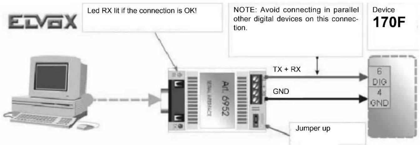
Connect the device through the serial interface 6952 or USB 6952/A according to the following figure and table:
flowchart
graph LR
    A["EDVGX"] --> B["LED Rx lit if the connection is OK!"]
    B --> C["Device 170F"]
    C --> D["TX + RX"]
    C --> E["GND"]
    C --> F["Jumper up"]
    style A fill:#f9f,stroke:#333
    style B fill:#ccf,stroke:#333
    style C fill:#cfc,stroke:#333
    style D fill:#fcc,stroke:#333
    style E fill:#fcc,stroke:#333
    style F fill:#fcc,stroke:#333
| Terminals 6952 or 6952/A | Terminal 170F |
| - | 4 |
| TX 6* |
* the connection to the PC operates only if the digital line is connected to terminal 6
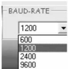
Start the program, select the COM of PC where the interface is connected, select then baud rate "1200" and click "Configura Principali Parametri" (Configure main Parameters).
Follow the monitor instructions to be able to read and/or modify the device parameters.
F
DESCRIPTION DES BORNES:
| Funcionamento Activação Dip 1 | Dip 2 Dip 3 Dip 4 | ||
| Só comando OFF --- --- --- | |||
| Número e comando ON --- --- --- | |||
| Desligar com reset --- ON --- --- | |||
| Activação por janela OFF --- ON --- | |||
| Funcionamento On / Off --- --- --- ON |
NOTE: The jumper P1 on the interphone terminal block must be cut in all interphones of each group with the same call from outside, but one.
Video-intercom panel
Additional push-button for lock
Camera with speech unit
Bulb for panel lighting
- Carefully read the instructions on this leaflet: they give important information on the safety, use and maintenance of the installation.
- After removing the packing, check the integrity of the set. Packing components (plastic bags, expanded polystyrene etc.) are dangerous for children. Installation must be carried out according to national safety regulations.
- It is convenient to fit close to the supply voltage source a proper bipolar type switch with 3 mm separation (minimum) between contacts.
- Before connecting the set, ensure that the data on the label correspond to those of the mains.
- Use this set only for the purposes designed, i.e. for electric door-opener systems. Any other use may be dangerous. The manufacturer is not responsible for damage caused by improper, erroneous or irrational use.
- Before cleaning or maintenance, disconnect the set.
- In case of failure or faulty operation, disconnect the set and do not open it.
- For repairs apply only to the technical assistance centre authorized by the manufacturer.
- Safety may be compromised if these instructions are disregarded.
- Do not obstruct opening of ventilation or heat exit slots and do not expose the set to dripping or sprinkling of water.
- Installers must ensure that manuals with the above instructions are left on connected units after installation, for users' information.
- All items must only be used for the purposes designed.
- This leaflet must always be enclosed with the equipment.
Directive 2002/96/EC (WEEE)
The crossed-out wheelie bin symbol marked on the product indicates that at the end of its useful life, the product must be handled separately from household refuse and must therefore be assigned to a differentiated collection centre for electrical and electronic equipment or returned to the dealer upon purchase of a new, equivalent item of equipment.
The user is responsible for assigning the equipment, at the end of its life, to the appropriate collection facilities.
Suitable differentiated collection, for the purpose of subsequent recycling of decommissioned equipment and environmentally compatible treatment and disposal, helps prevent potential negative effects on health and the environment and promotes the recycling of the materials of which the product is made. For further details regarding the collection systems available, contact your local waste disposal service or the shop from which the equipment was purchased.
Risks connected to substances considered as dangerous (WEEE).
According to the WEEE Directive, substances since long usually used on electric and electronic appliances are considered dangerous for people and the environment. The adequate differentiated collection for the subsequent dispatch of the appliance for the recycling, treatment and dismantling (compatible with the environment) help to avoid possible negative effects on the environment and health and promote the recycling of material with which the product is compound.
natural_image
Pure electrical circuit lines without any symbolsF
CONSEILS POUR L'INSTALLATEUR
Directive 2002/96/CE (WEEE, RAEE)
- Communicating in style
- TERMINAL DESCRIPTION:
- STANDARD OPERATION
- Programming Procedure
- OPERATING MODE CHANGE PROCEDURE:
- PROCEDURE FOR THE CONNECTION TO THE "PC DIGIBUS ANALYSER" SOFTWARE
- F
- DESCRIPTION DES BORNES:
- Directive 2002/96/EC (WEEE)
- Risks connected to substances considered as dangerous (WEEE).
- CONSEILS POUR L'INSTALLATEUR
- Directive 2002/96/CE (WEEE, RAEE)
Brand : Vimar
Model : ELVOX 170F
Category : Electrical relay