
168754 - Battery charger SILVERLINE - Free user manual and instructions
Find the device manual for free 168754 SILVERLINE in PDF.
| Product Type | Inverter / Battery Charger |
| Brand | Silverline |
| Model | 168754 |
| Input Voltage | 11-15 V (12 V) DC |
| Max Input Current | 100 A (peak 160 A, 1 s) |
| Output Voltage | 230 V~ |
| Output Frequency | 50 Hz |
| Waveform | Modified sine wave |
| USB Output | 5 V DC, 500 mA |
| Main Socket | 2 universal 230 V sockets |
| Max Continuous Power | 1000 W (4.35 A) |
| Efficiency | > 88% |
| No Load Current | < 0.8 A |
| Protections | Overvoltage (16 V), undervoltage (10 V), overload, short circuit, overtemperature (55 °C) |
| Dimensions | 250 x 165 x 72 mm |
| Weight | 2.2 kg |
| Protection Class | Class I (grounded) |
| Warranty | 3 years (registration within 30 days) |
| Operating Temperature | 10-27 °C |
| Included Accessories | 12 V cable |
Frequently Asked Questions - 168754 SILVERLINE
User questions about 168754 SILVERLINE
0 question about this device. Answer the ones you know or ask your own.
Ask a new question about this device
Download the instructions for your Battery charger in PDF format for free! Find your manual 168754 - SILVERLINE and take your electronic device back in hand. On this page are published all the documents necessary for the use of your device. 168754 by SILVERLINE.
USER MANUAL 168754 SILVERLINE
natural_image
Coiled black cable with metal clamps, no visible text or symbolsRANGE JSILVERLINEC® 40V Inverter (500W)
12V Inverter 100
1000W (2 x 300W)
English 4
Français ...... 10
Deutsch 16
Español 22
Italiano 28
Nederlands......34
Introduction
Thank you for purchasing this Silverline tool. This manual contains information necessary for safe and effective operation of this product. This product has unique features and, even if you are familiar with similar products, it is necessary to read this manual carefully to ensure you fully understand the instructions. Ensure all users of the tool read and fully understand this manual.
Description of Symbols
The rating plate on your tool may show symbols. These represent important information about the product or instructions on its use

Wear hearing protection
Wear eye protection
Wear breathing protection
Wear head protection

Wear hand protection

Read instruction manual

Caution!

Risk of electrocution

Risk of fire!

Risk of explosion!

NO open flames!

No smoking!

Conforms to relevant legislation and safety standards

Environmental Protection
Waste electrical products should not be disposed of with household waste. Please recycle where facilities exist. Check with your local authority or retailer for recycling advice

Class I construction (protective earth)
| V Volts | |
| ~ Alternating current | |
| A Ampere | |
| n_o | No load speed |
| Hz Hertz | |
| W, kW Watt, kilowatt | |
| /min or min^-1 | (revolutions or reciprocation)per minute |
Specification
Input voltage range: 11-15V (12V) DC
Max input current: 100A (160A peak, 1 second)
Output voltage: 230V\~
Output frequency: 50Hz
Waveform:......Modified Sine
USB output: 5V DC, 500mA
Mains sockets: 2 Universal
Mains socket protection class:....(⊥)
Max continuous output power: 1000 W (4.35A)
Surge capacity/time: 1600W for one second
Efficiency: >88%
No load current draw: <0.8A
Low voltage alarm: 10.5±0.5V
Low voltage shutdown:....10±0.5V
High voltage cut-off: 15.5±0.3V
Maximum operating temperature: <65°C
Recommended ambient temperature: 10-27°C
Protection features: Input over voltage (16V)
Input low voltage
Output overload
Output short-circuit
Overheat (65°C)
Earth/Ground : Inverter case connected to AC mains socket earth pin
Dimensions: 250 x 165 x 72mm
Weight: 2.2kg
As part of our ongoing product development, specifications of Silverline products may alter without notice.
General Safety
WARNING Read all safety warnings and all instructions. Failure to follow the warnings and instructions may result in electric shock, fire and/or serious injury.
WARNING: This device is not intended for use by persons (including children) with reduced, physical or mental capabilities or lack of experience or knowledge unless they have been given supervision or instruction concerning use of the device by a person responsible for their safety. Children must be supervised to ensure that they do not play with the device.
Save all warnings and instructions for future reference.
1) Work area safety
a) Do not operate electrical devices in explosive atmospheres, such as in the presence of flammable liquids, gases or dust. Electrical devices create sparks which may ignite the dust or fumes.
2) Electrical safety
a) Electrical plugs must match the outlet. Never modify the plug in any way. Do not use any adapter plugs with earthed (grounded) devices. Unmodified plugs and matching outlets will reduce risk of electric shock.
b) Avoid body contact with earthed or grounded surfaces, such as pipes, radiators, ranges and refrigerators. There is an increased risk of electric shock if your body is earthed or grounded.
c) Do not expose non-waterproof electrical devices to rain or wet conditions. Do not submerge non-pressure-rated devices in water. Water entering an electrical device will increase the risk of electric shock.
d) Do not abuse the power lead. Never use the lead for carrying, pulling or unplugging the device. Keep lead away from heat, oil, sharp edges or moving parts. Damaged or entangled power leads increase the risk of electric shock.
e) If operating an electrical device in a damp location is unavoidable, use a residual current device (RCD) protected supply. Use of an RCD reduces the risk of electric shock.
WARNING: When used in Australia or New Zealand, it is recommended that devices are ALWAYS supplied via Residual Current Device (RCD) with a rated residual current of 30mA or less.
3) Personal safety
a) Stay alert, watch what you are doing and use common sense when operating an electrical device. Do not use potentially dangerous electrical devices while you are tired or under the influence of drugs, alcohol or medication. A moment of inattention while operating potentially dangerous devices may result in serious personal injury.
b) Use personal protective equipment including eye protection where appropriate. Protective equipment used for appropriate conditions will reduce personal injuries.
c) Prevent unintentional starting. Ensure the switch is in the off-position before connecting to a power source. Carrying electrical devices with your finger on the switch or energising devices that have the switch on invites accidents.
d) Do not overreach. Keep proper footing and balance at all times. This enables better control of the device in unexpected situations.
4) Use and Care
a) Do not force the device. Use the correct device for your application. The correct device will do the job better and safer at the rate for which it was designed.
b) Do not use the electrical device if the switch does not turn it on and off. Any device that cannot be controlled with the switch is dangerous and must be repaired.
c) Disconnect the power source before making any adjustments, changing accessories, or storing electrical devices. Such preventive safety measures reduce the risk of starting the device accidentally.
d) Store idle devices out of the reach of children and do not allow persons unfamiliar with the device or these instructions to operate it. Electrical devices may be dangerous in the hands of untrained users.
e) Maintain electrical devices. Check for defects of parts and any other condition that may affect the device's operation. If damaged, have the device repaired before use. Many accidents are caused by poorly maintained electrical devices.
f) Use the device and its accessories in accordance with these instructions, taking into account the conditions and the task to be performed. Use of the device for operations different from those intended could result in a hazardous situation.
5) Service
a) Have your electrical devices serviced by a qualified repair person using only identical replacement parts. This will ensure that the safety of the device is maintained.
Inverter Safety
WARNING: Inverters produce the same dangerous and potentially lethal AC voltage as domestic mains sockets.
WARNING: DO NOT use the inverter in any location where flammable gases may be present, including inside engine bays and battery compartments. Lead acid batteries can generate flammable fumes. Electronic devices and making electrical connections can cause sparks that ignite those fumes.
WARNING: If skin or clothing comes into contact with acid from leaking lead acid batteries, remove contaminated clothing immediately, wash affected skin with soap and copious amounts of fresh water. If acid enters the eye, flush under cool running water for a minimum of 15 minutes and seek urgent medical attention.
WARNING: DO NOT use the inverter near flammable materials or objects that can be affected by heat. The inverter may become very hot during extended periods of full power use.
WARNING: People with heart pacemakers should consult their physician before use. Strong electromagnetic fields in close proximity to a heart pacemaker could cause pacemaker interference or pacemaker failure.
a) DO NOT use the inverter in a damp environment, where the air has high moisture content or any position where the inverter could accidentally come into contact with water. This may prevent use in a marine environment especially for smaller vessels
b) When used in a stationary location the inverter must be fully protected from the weather and kept under cover
c) Allow sufficient space around the inverter for cooling. DO NOT place on carpets or rugs as they can block vents on the bottom of the inverter and are a fire hazard
d) Use in cool to moderate ambient temperatures only. DO NOT place on top or near a heating vent
e) ALWAYS confirm devices are suitable for use with moderated sine wave current. DO NOT attempt to power devices that require pure sine wave current
f) DO NOT use on any vehicles with power supplies other than 12V. Some vehicles use 24V or 6V systems.
g) DO NOT use DC cables that are not suitable for the maximum input current rating of the inverter. Neither the vehicle or the inverter can sense if inadequate cables are connected and there is a fire and explosion risk to using such cables
h) DO NOT connect any AC load circuit in which the neutral conductor is connected to protective earth or to the minus pole of the source battery. This could severely damage both devices
i) DO NOT install this inverter into a building's electrical system. It is not designed to be integrated safely into such an electrical system and has not been tested or certified to meet building electrical standards. Such installations may create a fire risk or electric shock hazard
j) DO NOT attempt to integrate the inverter in any pre-existing 230V distribution system in a motorhome or caravan. Such work should be done by a qualified electrician
k) Connecting an inverter to an existing fused circuit of a vehicle's electrical system can be dangerous and lead to substantial damage. ALWAYS connect an inverter directly to a vehicle battery unless you are absolutely sure it is safe to do otherwise
Note: If you wish to have the inverter turned on and off with the vehicle's ignition, use a fused relay circuit so that a low current circuit can turn on and off a high current connection that is directly connected to the battery.
Product Familiarisation
| 1 | Universal Mains Sockets |
| 2 | Power Indicator Light |
| 3 | Low Battery Indicator Light |
| 4 | USB Socket |
| 5 | On/Off Switch |
| 6 | Mounting Holes |
| 7 | 12V Negative Connector (-) |
| 8 | 12V Positive Connector (+) |
| 9 | 12V Cables |
Unpacking Your Tool
Carefully unpack and inspect your tool. Familiarise yourself with all its features and functions.
Ensure that all parts of the tool are present and in good condition. If any parts are missing or damaged, have such parts replaced before attempting to use this tool.
Intended Use
Device for converting 12V DC into AC mains voltage so normal mains-operated devices can be used from DC power. The device can be used in fixed locations or in vehicles.
Before Use
Installing your inverter
WARNING: If you have any doubt about your ability to install an inverter, have it installed by or consult a qualified electrician.
WARNING: If the inverter is modified to bond neutral to earth, this will invalidate the suggested earth wiring in this manual, including connecting earth to a vehicle's chassis.
- Always read the vehicle's manual in combination with these instructions when installing an inverter
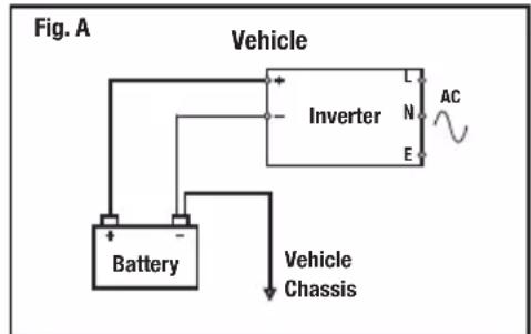
- Always mount the inverter level and horizontal so that the internal fans extract the heat with maximum efficiency. The inverter can be mounted upside down as long as the body remains level and horizontal. Use the Mounting Holes (6) to secure to a surface. The earth pin connection of the universal socket is connected to the inverter's external case. The inverter does not require a connection to earth in a vehicle so ensure the inverter is kept electrically isolated from the vehicle chassis
- The inverter should ideally be located as close as possible to the battery but not placed in the engine bay or battery compartment
- Ensure the position of the inverter allows for easy access to the On/Off Switch (5)
- Do not use the inverter in a dirty or dusty environment. It is important the inverter has good ventilation and the fan outlets, vents and mains socket are free of dust and debris
- Always position the inverter away from direct sunlight and other heat sources. Only use the inverter when the ambient air temperature is between 10-27°C
- Allow adequate ventilation by ensuring there is always at least 25mm clear space around the inverter. Do not place anything on top of the inverter
- There are Mounting Holes (6) on the case body for securely mounting the inverter with screws or other fasteners.
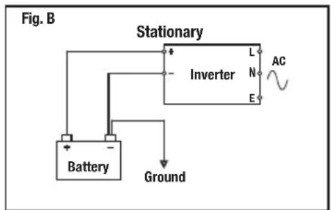
- In a stationary location, the battery or battery bank MUST be connected to a ground rod (a metal rod driven into the earth) or other earthing point (Fig. B)
- When used in a vehicle, the inverter should only be used with 12V DC negative earth electrical system. Use with any other type of vehicle earth system may be dangerous and could cause permanent damage to the inverter and other electrical components
Connecting to a battery
WARNING: When working next to, or moving lead acid batteries ensure you are wearing splash resistant safety goggles and electrically insulated gloves.
WARNING: The maximum input current of this inverter (95A) exceeds the output of most alternators fitted to cars and light vans, which normally have a current output of approximately 60-70A. This inverter used to maximum capacity for an extended duration, even while the engine is running, will require current well beyond the spare current capacity of the alternator, and will discharge the battery until fully discharged and the vehicle cannot be started.
IMPORTANT: Normal automotive (SLI) batteries are not recommended for use with this inverter if the inverter is used at its maximum output for extended periods - especially if the inverter is used in a stationary position that does not benefit from having a vehicle alternator providing part of the current requirements. Recommended battery types are deep cycle (leisure) or traction batteries. These are purposely designed to be depleted fully at a low to medium rate and recharged frequently, but do not provide the peak current output of automotive batteries that is required for starting a vehicle.
Notes:
- If you wish to replace the supplied 12V cables with longer cables, connect cables that are suitable for the sustained inverter current demands, not peak/surge (see Specification). Also make sure the insulation of the cable is correct for the environment the cables will be used in
- To use this inverter at full capacity in a vehicle may require fitting of a higher performance alternator
- When connecting multiple batteries in parallel, ideally all batteries should be the same type, manufacturer, age and capacity. This will help provide the same level of current and runtime across all batteries and mean they will age and can be replaced at the same time with minimal waste of battery life. A worn battery with reduced capacity is the weak link in a battery bank and prevents the full benefits of a bank being realised
- It is safer to use normal automotive (SLI) batteries in a parallel arrangement with an inverter as the sustained high discharge rate is shared across multiple batteries. This can help such batteries last longer, which otherwise may wear out very quickly when used individually with inverters
- If fitting an inline fuse to improve protection against short circuits and overloads, connect inline to the cable that attaches to the inverter's 12V positive terminal. Select a suitable fuse based on the maximum sustained input current of the inverter, and choose a fuse at the closest value above this. So an inverter rated at 95A would need a 100A continuous (anti-surge/time delay) rated fuse. Do not use a quick or fast blow type fuse due to the peak current demands of AC devices when they are started. A suitable fuse and fuse holder are available as Maxi blade type or Mega™ fuses for higher values
-
When batteries need charging in a stationary installation and the battery charger used allows for charging multiple batteries simultaneously, make sure the inverter is switched off or disconnected while charging to prevent possible damage to the inverter and battery charger. Check the instructions supplied with the battery chargers for exact information
-
Switch the On/Off Switch (5) to the off position
-
Connect the 12V Cables (9) to the battery as shown in Fig. A for vehicles or boats, or Fig. B for a stationary installation. Make sure the cables are not shorted together
-
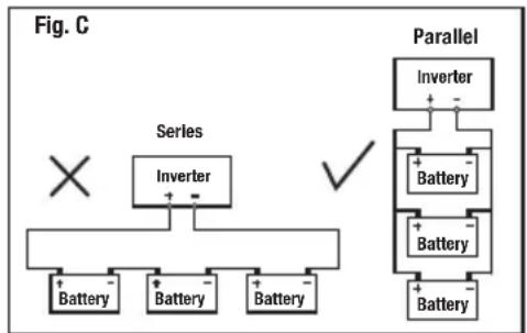
If you are connecting multiple batteries in a stationary installation, ensure they are connected in parallel (Fig. C). Do not connect in series as the inverter and possibly the batteries will be damaged. Parallel requires all negative battery terminals to be connected to the negative terminal of the inverter and all positive battery terminals to be connected to the positive terminal of the inverter. Double check the batteries are correctly connected before connecting to the inverter
-
Remove the knobs of the 12V Connectors (7) and (8) and attach the free ends of the 12V cables. Connect the black 12V cable to the Negative Connector (-) and the red 12V cable to the Positive Connector (+). Tighten the knobs. Check the cables are connected to the correct connectors. Connecting to the Positive Connector (+) of the inverter should be the final connection made. It is important that the polarity is correct as the inverter's internal fuses will be blown by incorrect polarity
flowchart
graph TD
    A["×"] --> B["Inverter"]
    B --> C["Battery"]
    B --> D["Battery"]
    B --> E["Battery"]
    F["Parallel"] --> G["Inverter"]
    G --> H["Battery"]
    G --> I["Battery"]
    G --> J["Battery"]
    H --> K["+"]
    I --> L["-"]
    J --> M["-"]
    N["✓"] --> O["Parallel"]
Operation
Connecting a mains device
WARNING: This inverter is not compatible with devices that have a capacitive power supply; due to their design they will not work with the simulated AC voltage (modified sine wave) of this inverter. Such power supplies are no longer sold from new in Europe due to their reliance on pure sine wave AC and are fairly rare. They do not meet current European safety standards but if you suspect your device has such a power supply, make sure you monitor the device when first connected. If it is a battery charger that contains a rechargeable battery of any type it is recommended not to try it due to the possibility of damage to the batteries.
WARNING: If the inverter is constantly running at a very high temperature or is shutting down in use, it is possible the device connected to the inverter is not ideally matched and should not be connected. Always monitor the inverter and mains device when connected for the first time for the first 5 minutes or so to ensure both are working correctly at normal temperatures, then check on the device every half hour for the first 2 hours. Once the device is confirmed as compatible mark it so its compatibility is recorded.
WARNING: The mains sockets fitted to the inverter are a universal type which accommodates a wide range of world mains plugs. It is important when using devices fitted with a non-UK or European plug that you check the device is compatible with 230V 50Hz. This is especially important for devices intended for the US market; these will normally be 120V 60Hz only and must not be connected. Only if the rating label of the product specifically states a wide input voltage and dual mains frequency, for example '100-240V - 50/60Hz' can they be used.
IMPORTANT: The inverter is reliant on being connected to a DC power source sufficient to power your AC mains devices. It is not a fault with the inverter if the current is inadequate to power your mains devices.
IMPORTANT: If you are using an RCD with the inverter check that the inverter is operating normally. As with all RCDs use the test button to make sure it is operating correctly before use. If the RCD is not operating normally with an inverter this does not indicate a fault with the inverter or RCD and is likely caused by either the modified sine wave output or lack of neutral/earth bonding you would get from normal domestic sockets.
IMPORTANT: The inverter may shut down as a vehicle engine is being started due to the high electrical current required by the vehicle starter motor. Ideally turn off the inverter before starting the vehicle.
Notes
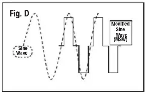
- The inverter simulates mains AC voltage using a modified sine wave (Fig. D). A small number of devices may not be compatible with this type of AC waveform. Most resistive load devices (kettles, filament bulbs etc) are compatible. Inductive loads, typically those that have electrically powered moving parts or have circuit boards with electronic components, are more likely to be incompatible. These have components that make use of magnetic fields and often require a high starting current as well as being more selective about the AC wave form. Generally even domestic mains sockets don't output pure sine wave AC but their waveform is closer to pure sine wave than a modified sine wave inverter. Many devices are designed to work with AC wave forms that are not pure sine wave, so most devices are compatible with modified sine wave output
- Some inductive load devices may consume slightly more current or produce more noise with modified sine wave AC compared to pure sine wave AC
- Some devices have huge starting current requirements which means even if the average power consumption is well within the inverter's rating the device will not be compatible. Pumps and compressors typically have the highest starting current requirements (a refrigerator is a common device of this type). Generally an inductive load with the same wattage power as a resistive load is less likely to be compatible due to starting current requirements although some resistive loads still have higher starting current requirements like filament bulbs
- If an inductive load device will not function at all with the inverter, or is not functioning correctly, connecting a resistive load device with the inductive load may enable it to function normally. A small lamp with a filament bulb may be suitable as a resistive load
- DO NOT use this inverter for sensitive devices such as medical equipment or any other critical or calibrated electronic device that may not be compatible with modified sine wave AC
- When used with AV devices, it is possible additional background noise will be heard in use and possible video distortion or interference. This could be due to many reasons, including interference from the inverter or vehicle electrics as well as the modified sine wave AC effecting components in the device. It is possible such a device simply will not be compatible with a modified sine wave inverter, and a pure sine wave inverter will be required for the device to work optimally
- Some devices, including laptops, mobile phones, and handheld electronic devices, have AC power supplies to generate DC that the main unit requires to operate or charge its battery. It is more efficient for such devices to be charged using a 12V charging lead (possibly supplied with the unit) as this eliminates the conversion loss from converting 12V DC to high voltage AC in the inverter and then high voltage AC back to low voltage DC in the AC power supply
- Some appliances (televisions, stereos, motors, neon lights etc) may require a much higher starting power than their rated power. If the appliance will not start, the maximum output of the inverter has been exceeded. To reduce the total load on the inverter it may be possible to start the device by turning off other devices connected to the inverter and then powering them up again, after you have started the device that needs a very high starting current. If the inverter switches off due to high starting current demands, this does not indicate a fault
-
When checking AC output from an inverter with a multimeter, unless the multimeter has a true RMS feature, it will give a low voltage reading from the output of a modified sine wave inverter. This is normal and not an indication that the inverter or multimeter is faulty
-
Use a plug-in power monitor plugged into a domestic AC mains socket to find out the true power consumption of an AC device. Ideally use a power monitor with a peak current facility that will indicate the required starting current of a device
- If the appliance to be connected does not have its wattage (W) indicated on it, the wattage can be calculated by multiplying the amperes (A) by 230
- When you have finished powering a mains device with the inverter, turn the On/Off Switch (5) to off. The inverter always consumes power when turned on. See 'Specification' for the inverter power consumption without load. It is possible for a the inverter to drain a battery and prevent starting of a vehicle if left on - even without a load
- Before connecting any appliance to the inverter, switch the On/Off Switch (5) to the 'ON' position. After a few moments, the green Power Indicator Light (2) will illuminate. The inverter is now ready for use
- Do not connect loads greater than the rated maximum continuous power output of the inverter (see Specification)
- Connect your AC device to either of the Universal Mains Sockets (1)
Calculating Load and Runtime
- Ah rating of batteries is an approximate figure that is rarely true when a battery is discharged at a very high rate. A 100Ah battery discharged at 5A for 20 hours is more likely to last 20 hours than when discharged at 100A for 1 hour which will likely be fully discharged before 1 hour
- To calculate the maximum wattage output of a battery for one hour, multiply its Ah figure by its voltage (12V) i.e. a 100Ah battery is capable of 1200W for one hour
- An easy way to calculate the approximate runtime of a mains device when connected to an inverter with a known amperes power consumption value, is to multiply by 20 and divide the Ah figure of the battery by this calculated figure to get an approximate figure in hours
- Convert Watts into Amperes by dividing Watts by voltage (230). Convert Amperes into Watts by multiplying Amperes by 230
Protection Features
- Input over voltage: the inverter will switch off if the input DC voltage reaches or exceeds 15.5V. This indicates a poorly-regulated electrical system in the vehicle
- Input low voltage: the inverter will switch off if the DC voltage is approximately 10V. This prevents damage to AC devices due to insufficient AC voltage. The DC voltage may already be inadequate for starting the vehicle at this point. The inverter will audibly indicate low voltage from approximately 10.5V to 10V before shutting down
- Output overload: the inverter will switch off if the sustained or peak current requirements of the AC device or devices is too high for the inverter or the peak starting current requirements are within the inverter specification but are lasting beyond the 1 second limit for peak current
- Output short-circuit: If there is a short circuit in the AC connections the inverter will shut off. This has possibly blown the internal fuses of the inverter and will need replacement at an authorised service centre
- Overheat protection: The inverter will shut off if the internal temperature of the inverter has reached approximately 65^ C. This may occur due to inadequate ventilation, incorrect installation, poor compatibility with an AC device, or simply due to the inverter being used for a long period at maximum capacity. The built-in fan of the inverter is temperature-controlled to reduce current demands of the inverter
IMPORTANT: Always try to prevent these protection features from operating in the first place. It is possible that damage has already occurred before they operate.
IMPORTANT: When restarting the inverter after shutdown make sure the issue has been corrected that caused the shutdown.
Using the USB socket
- The inverter is fitted with a USB socket (4), which provides a maximum of 500mA current. If you have a device that can be charged via USB or mains always use the USB as it makes more efficient use of energy
Accessories
A wide range of Silverline products are available from your stockist including power tools compatible with this inverter.
Maintenance
- WARNING: The inverter contains no user serviceable parts. Some internal components retain a dangerous high charge level even when disconnected from power. In the event a short circuit occurs and blows the internal fuses, even though spare fuses may be supplied these should be replaced by an authorised service centre or qualified electrician.
Cleaning
- Keep your machine clean at all times. Dirt and dust will cause internal parts to wear quickly, shortening the machine's service life. Clean the body of your machine with a soft brush, or dry cloth. If available, use clean, dry, compressed air to blow through the ventilation holes
Disposal
Always adhere to national regulations when disposing of power tools that are no longer functional and are not viable for repair.
- Do not dispose of power tools, or other waste electrical and electronic equipment (WEEE), with household waste
- Contact your local waste disposal authority for information on the correct way to dispose of power tools
WARNING: Do not dispose of lead acid batteries with household waste.
Troubleshooting
| Problem Cause Solution | ||
| Inverter will not switch on | Low battery voltage Charge or replace battery | |
| An incompatible AC device is connected Disconnect AC device | ||
| Inverter in thermal shutdown Allow inverter to cool before switching on | ||
| DC cables are poorly connected Check DC leads for damage and secure connections | ||
| Internal fuses 'blown' possibly due to short circuit Have inverter serviced at an authorised service centre | ||
| Inline fuse blown if fitted Replace fuse | ||
| High alternator voltage Vehicle electrical system may have poor voltage regulation and require repair | ||
| Low voltage alarm on continuously or Low voltage shutdown operating | One or more batteries in a battery bank is faulty or end of service life | Replace battery or batteries |
| DC cables are inadequate or poorly connected Recheck cables are suitable and correctly connected | ||
| Vehicle electrical system is under very high load with battery at low charge and alternator is not able to charge both battery and provide adequate power to inverter | Inverter current demands are too high for the vehicle's electrical system. Reduce current demands or upgrade vehicle electrical system | |
| Low capacity battery that is only capable of handling high current demands from the inverter for a short time before a voltage drop | Replace battery with higher capacity model or if possible a deep cycle (leisure) or traction battery which are more suitable for inverters | |
| Low output voltage | Incorrectly measured with a multimeter or other voltage measurement tool without a true RMS mode which will give a low voltage reading | Measure with a true RMS multimeter or voltage measuring tool |
| AC mains device causes inverter to go into overload shutdowntrekker schakelaar wordt ingeknepen | Device requires either too much current continuously or has too high starting current requirements | Device not compatible with inverter or you have overloaded inverter with too many AC devices |
| AC mains device will not start but inverter does not go into overload shutdown | Insufficient DC power. Battery or batteries simply not capable of delivering the required level of current | Calculate the required DC current and check the DC current available is sufficient |
| Inductive load AC device not compatible with modified sine wave AC | Try pairing with a low power resistive load device like a small filament lamp | |
| AC device not compatible | ||
| AC device runs hot or is more noisy than normal but operates satisfactorily | AC device not fully compatible with modified sine wave AC It is recommended not to use the device | |
| AC device with a built-in timer or clock is not keeping accurate time so its functions are not correctly timed | If the device uses the AC waveform to regulate its timer rather than a crystal oscillator it will not work correctly with a modified sine wave inverter | Device is not fully compatible |
| AC power line network adapter does not operate | These devices do not normally work correctly with a modified sine wave AC waveform | Use normal network cabling which is also a more efficient use of power |
| RCD plugged into inverter does not operate normally | RCD is not compatible with inverter DO NOT use with inverter | |
| AC device abnormal operation | Incompatible with modified sine wave AC output | DO NOT use with inverter |
| AC device instructions gives warning about not using with inverters | This indicates the device is not compatible with a modified sine wave inverter and may be damaged by doing so | DO NOT use with inverter |
| Video and/or audio interference when AV equipment is used with inverter | Inverter is used too close to aerial | Move inverter or aerial |
| Aerial cable not shielded or insufficiently shielded | Use fully shielded cable with correctly fitted connectors | |
| AV equipment not operating correctly with modified sine wave output | AV equipment not compatible with inverter | |
| AV equipment picking up interference from vehicle ignition | Consult a vehicle electrician on how to suppress interference | |
Silverline Tools Guarantee
This Silverline product comes with a 3 year guarantee
Register this product at www.silverlinetools.com within 30 days of purchase in order to qualify for the 3 year guarantee. Guarantee period begins according to the date of purchase on your sales receipt.
Registering your purchase
Registration is made at silverlinetools.com by selecting the Guarantee Registration button. You will need to enter:-
- Your personal details
• Details of the product and purchase information
Once this information is entered your guarantee certificate will be created in PDF format for you to print out and keep with your purchase.
Terms & Conditions
Guarantee period becomes effective from the date of retail purchase as detailed on your sales receipt.
PLEASE KEEP YOUR SALES RECEIPT
If this product develops a fault within 30 days of purchase, return it to the stockist where it was purchased, with your receipt, stating details of the fault. You will receive a replacement or refund.
If this product develops a fault after the 30 day period, return it to:
Silverline Tools Service Centre
PO Box 2988
Yeovil
BA21 1WU, UK
The guarantee claim must be submitted during the guarantee period.
You must provide the original sales receipt indicating the purchase date, your name, address and place of purchase before any work can be carried out.
You must provide precise details of the fault requiring correction.
Claims made within the guarantee period will be verified by Silverline Tools to establish if the deficiencies are related to material or manufacturing of the product.
Carriage will not be refunded. Items for return must be in a suitably clean and safe state for repair, and should be packaged carefully to prevent damage or injury during transportation. We may reject unsuitable or unsafe deliveries.
All work will be carried out by Silverline Tools or its authorized repair agents.
The repair or replacement of the product will not extend the period of guarantee
Defects recognised by us as being covered by the guarantee shall be corrected by means of repair of the tool, free of charge (excluding carriage charges) or by replacement with a tool in perfect working order.
Retained tools, or parts, for which a replacement has been issued, will become the property of Silverline Tools.
The repair or replacement of your product under guarantee provides benefits which are additional to and do not affect your statutory rights as a consumer.
What is covered:
The repair of the product, if it can be verified to the satisfaction of Silverline Tools that the deficiencies were due to faulty materials or workmanship within the guarantee period.
If any part is no longer available or out of manufacture, Silverline Tools will replace it with a functional replacement part.
Use of this product in the EU.
What is not covered:
Silverline Tools does not guarantee repairs required as a result of:
Normal wear and tear caused by use in accordance with the operating instructions eg blades, brushes, belts, bulbs, batteries etc.
The replacement of any provided accessories drill bits, blades, sanding sheets, cutting discs and other related items.
Accidental damage, faults caused by negligent use or care, misuse, neglect, careless operation or handling of the product.
Use of the product for anything other than normal domestic purposes.
Change or modification of the product in any way.
Use of parts and accessories which are not genuine Silverline Tools components.
Faulty installation (except installed by Silverline Tools).
Repairs or alterations carried out by parties other than Silverline Tools or its authorized repair agents.
Claims other than the right to correction of faults on the tool named in these guarantee conditions are not covered by the guarantee.
CE Declaration of Conformity
The undersigned: Mr Darrell Morris
as authorized by: Silverline Tools
Declares that
This declaration has been issued under the sole responsibility of the manufacturer.
The object of the declaration is in conformity with the relevant Union harmonisation Legislation.
Identification code: 168754
Description: Inverter 1000W
Conforms to the following directives and standards:
• Low Voltage Directive 2006/95/EC
• EMC Directive 2004/108/EC
• RoHS Directive 2011/65/EU
• EN 61558-2-16:2009
• EN 61558-1:2005+A1:2009
• EN 62311:2008
• EN 61000-6-3:2007+A1:2011
• EN 61000-6-1:2007
Notified body: TÜV Rheinland.
The technical documentation is kept by: Silverline
Date: 06/01/2015
Signed :

Mr Darrell Morris
Managing Director
Name and address of the manufacturer:
Powerbox International Limited, Company No. 06897059. Registered address: Powerbox,
Boundary Way, Lufton Trading Estate, Yeovil, Somerset BA22 8HZ, United Kingdom.
Introduction
Silverline Tools Service Centre
PO Box 2988
Yeovil
Silverline Tools Service Centre
PO Box 2988
Yeovil
Silverline Tools Service Centre
PO Box 2988
Yeovil
BA21 1WU, GB
Silverline Tools Service Centre
PO Box 2988
Yeovil
BA21 1WU, GB
natural_image
Exterior view of a silver linear electronic device (no visible text or symbols on the body)
3 Year Guarantee
*Register online within 30 days. Terms & Conditions apply

Garantie de 3 ans
- RANGE JSILVERLINEC® 40V Inverter (500W)
- 12V Inverter 100
- Introduction
- Description of Symbols
- Environmental Protection
- Specification
- General Safety
- 1) Work area safety
- 2) Electrical safety
- 3) Personal safety
- 4) Use and Care
- 5) Service
- Inverter Safety
- Product Familiarisation
- Unpacking Your Tool
- Intended Use
- Before Use
- Installing your inverter
- Connecting to a battery
- Notes:
- Operation
- Connecting a mains device
- Notes
- Calculating Load and Runtime
- Protection Features
- Using the USB socket
- Accessories
- Maintenance
- Cleaning
- Disposal
- Silverline Tools Guarantee
- This Silverline product comes with a 3 year guarantee
- Registering your purchase
- Terms & Conditions
- PLEASE KEEP YOUR SALES RECEIPT
- Silverline Tools Service Centre
- PO Box 2988
- Yeovil
- BA21 1WU, UK
- What is covered:
- What is not covered:
- CE Declaration of Conformity
- BA21 1WU, GB
- Year Guarantee
- Garantie de 3 ans
Brand : SILVERLINE
Model : 168754
Category : Battery charger