
MasterCella compact - Temperature regulator Carel - Free user manual and instructions
Find the device manual for free MasterCella compact Carel in PDF.
| Product Type | Temperature regulator for refrigeration units |
| Brand | Carel |
| Model | MasterCella compact |
| Power supply | 230 Vac, +10% -15%, 50/60 Hz |
| Power consumption | 7 VA |
| Dimensions (L x H x D) | 190 x 160 x 65 mm |
| Protection rating | IP65 |
| Enclosure material | Self-extinguishing plastic (UL94-V0) |
| Mounting type | Panel or wall mount |
| Operating temperature range | 0 to 50 °C |
| Operating relative humidity | 20 to 80% RH (non-condensing) |
| Inputs | 2 configurable digital inputs (dry contact), 2 NTC probes (10 kΩ at 25 °C) |
| Relay outputs | Compressor, defrost, fans, light/aux, alarm |
| Display | 2.5 digits, LED indicators |
| Main functions | Compressor management, defrost (electric or hot gas), fans, alarms, continuous cycle, light |
| Cleaning | Use only neutral detergents and water |
| Safety | Installation by qualified personnel, disconnect before any intervention |
| Insulation class | Class II |
| Compliance | EN 60730-1 |
Frequently Asked Questions - MasterCella compact Carel
User questions about MasterCella compact Carel
0 question about this device. Answer the ones you know or ask your own.
Ask a new question about this device
Download the instructions for your Temperature regulator in PDF format for free! Find your manual MasterCella compact - Carel and take your electronic device back in hand. On this page are published all the documents necessary for the use of your device. MasterCella compact by Carel.
USER MANUAL MasterCella compact Carel
natural_image
Simple gray oval shape with a vertical line inside, no text or symbols present.AVVERTENZE IMPORTANTI

PRIMA DI INSTALLARE O INTERVENIRE SULL'APPARECCHIO, LEGGERE ATTENTAMENTE E SEGUIRE LE ISTRUZIONI CONTENUTE IN QUESTO MANUALE.
Fig. 1.2.1
We wish to save you time and money!
We can assure you that a thorough reading of this manual will guarantee correct installation and safe use of the product described.

IMPORTANT

BEFORE INSTALLING OR OPERATING ON THE DEVICE, CAREFULLY READ THE INSTRUCTIONS IN THIS MANUAL.
This instrument has been designed to operate without risks only if:
- installation, operation and maintenance are performed according to the instructions of this manual;
• environmental conditions and supply voltage fall within the values indicated here below.
Any different use or changes which have not been previously authorised by the manufacturer, are considered improper.
Responsibility for injures or damage caused by improper use will fall exclusively on the user.
Warning: voltage is present in some electrical components of this instrument, thus all the service or maintenance operations must be performed by expert and skilled personnel only, aware of the necessary precautions to be taken.
Before accessing the internal parts, disconnect the power supply.
Disposing of the parts of the controller
The controller is made from metal parts and plastic parts.
All these parts should be disposed of according to local standards on waste disposal.
Cleaning the controller
Only use neutral detergents and water.
Contents
Introduction 23
1. Installation and connections 23
1.1 General warnings – installation and connection environments 23
1.2 Panel installation 24
1.3 Wall-mounted installation 25
1.4 Electrical connections 26
2. Function and description of the buttons 27
3. Operation 28
3.1 Display 28
3.3 Manual defrost 28
3.4 Silencing the buzzer 28
3.5 Light ON/OFF 28
3.2 Set Point (required temperature value) 28
3.6 Continuous cycle 28
4. Parameters 29
4.1 First level - frequent parameters 29
4.2 Second level - configuration parameters 29
4.3 Modifying and saving the parameters 29
4.3.1 Modifying 29
4.3.2 Saving 29
4.4 Configuring the digital inputs 30
4.4.1 Duty setting selection (parameters c4 and A6) 30
4.5 Table of the parameters 31
5. Alarms, signals and troubleshooting 33
6. Technical specifications 34
6.1 General characteristics 34
6.2 Electrical specifications 34
6.2.1 Inputs 34
6.2.2 Outputs 34
6.3 Mechanical characteristics 35
6.4 Dimensions 35
Introduction
MasterCella is a control for static or ventilated refrigerated units. It manages all devices: compressors, fans, defrost, alarms and lights. The enclosure is IP65 and cable connection is extremely easy thanks to an easily removable front cover. MasterCella belongs to a range of controls able to meet customer requests.
Thanks to the chosen case, the MasterCell can be both panel-mounted and wall-mounted.
1. Installation and connections
1.1 General warnings – installation and connection environments
The following conditions represent the correct installation:
- avoid installing the instrument in environments featuring: wide and rapid fluctuations in ambient temperature, relative humidity over 80%, exposure to direct jets of pressurised water, high levels of electromagnetic and/or radio-frequency interference (e.g. transmitting antennae);
- use cable terminals that are suitable for the terminals being used. Loosen each screw and insert the cable ends, then tighten the screws. Once this operation has been completed, lightly tug the cables to check that they are sufficiently tight;
- separate as much as possible the probe and digital input cables from cables carrying inductive loads and power cables, to avoid any electromagnetic disturbance. Never lay power cables and probe cables in the same channels (including those for the electrical cables). Do not install the probe cables in the immediate vicinity of power devices (contactors, thermal overload switches or the like);
- reduce the path of the sensor cables as much as possible and avoid laying spiral paths around power devices. To extend the probe cables, use cables with a minimum cross-section of at least 0.5mm ^4 ;
- the cables to be connected to the contacts of the controller must be resistant to the maximum operating temperature, determined by summing the maximum ambient temperature envisaged to the heat produced by the controller equal to 20^ C;
- a 50mAT, 250Vac slow-blow fuse must be fitted upstream of the power supply to the controller;
- protect the power supply to the loads connected to the controller (compressor, defrost, fan, etc..) using suitable devices (thermal-magnetic overload switch/switches), rated according to the corresponding loads connected.
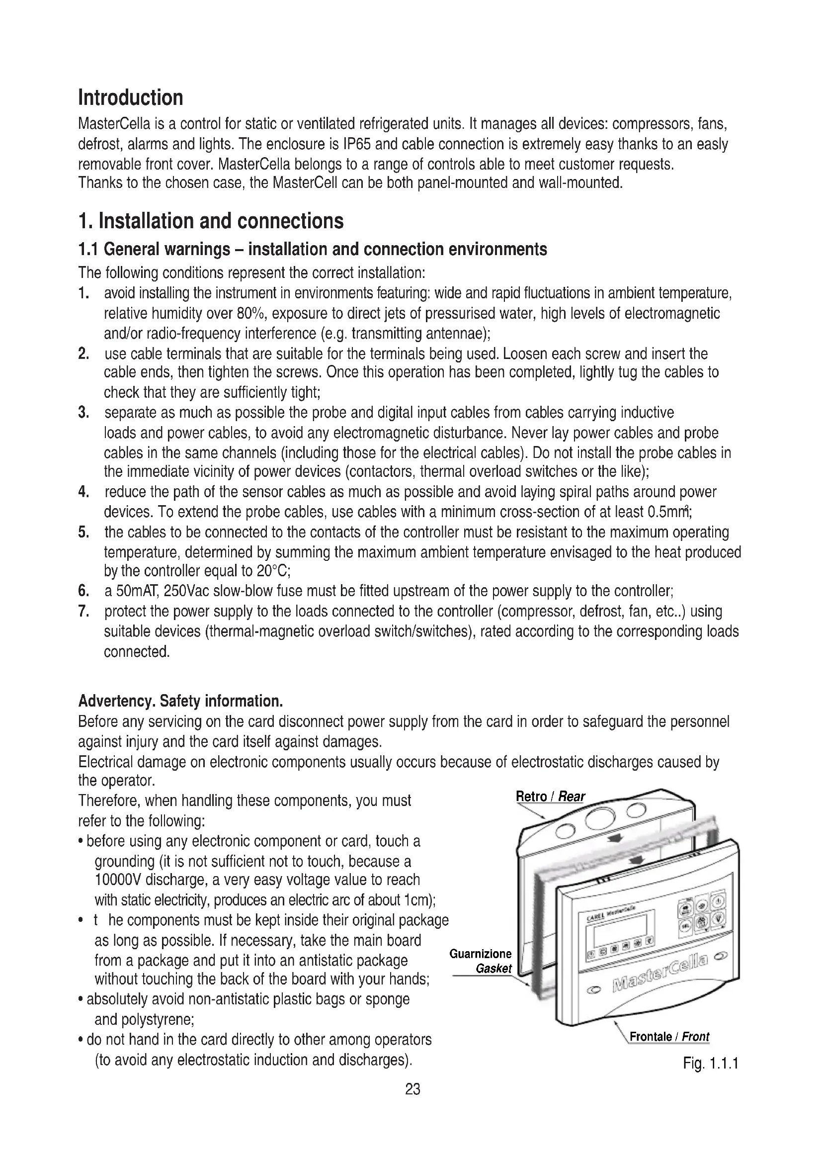
Advertency. Safety information.
Before any servicing on the card disconnect power supply from the card in order to safeguard the personnel against injury and the card itself against damages.
Electrical damage on electronic components usually occurs because of electrostatic discharges caused by the operator.
Therefore, when handling these components, you must refer to the following:
- before using any electronic component or card, touch a grounding (it is not sufficient not to touch, because a 10000V discharge, a very easy voltage value to reach with static electricity, produces an electric arc of about 1cm);
- t he components must be kept inside their original package as long as possible. If necessary, take the main board from a package and put it into an antistatic package without touching the back of the board with your hands;
- absolutely avoid non-antistatic plastic bags or sponge and polystyrene;
- do not hand in the card directly to other among operators (to avoid any electrostatic induction and discharges).
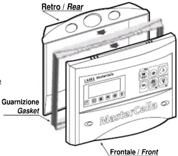
Fig. 1.1.1
1.2 Panel installation
In reference to Fig. 1.2.1 and the corresponding parts:
- Make a hole in the panel with the following dimensions: 182x153mm.
- Unscrew the two frontal screws (Fig. 1.2.1, a, b) and take out the central door (part c).
- Unscrew the two screws (parts d, e) that keep the lower and frontal cover of the MasterCella connected and separate the two parts.
- Insert the panel gasket in the front panel, on top of the internal gasket.
- Make two holes in the back part (Fig. 1.3.1 in the perforated part - parts f, g).
- Join the back part and the front, with the panel in between, and fix the whole unit with the two screws (dimensions: 4x20*mm) that are contained in the kit.
* max length 20 mm.
Warning: the two upper fastening teeth (part h) must be removed from the front panel before inserting the unit in the panel. Make the hole on the upper (part i) or lower part (part l) of the rear for the passage of the cables. The step of the thread can vary from PG9 (diameter 16mm) to PG21 (diameter 29mm).
A drill or miller should be used to assist the drilling operation. Connect the wires to the terminal block. Retighten the screws (parts d, e), then close the door (part c).
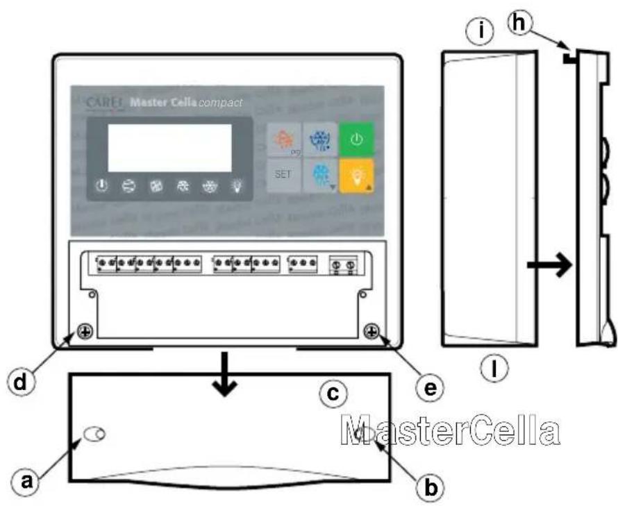
Fig. 1.2.1
1.3 Wall-mounted installation
With reference to Fig. 1.3.1:
- Unscrew the two frontal screws (Fig. 1.1.1, parts a, b) and remove the central door (part c).
- Unscrew the two screws (parts d, e) that keep the lower and frontal cover of the MasterCella connected and separate the two parts.
- Once having decided where to pass the cable duct or the cables (from above or from below) and having made the proper holes (in the part drilled in advance - parts i, l) for cablepresses and pipepresses, make three holes (parts m, n, o) both in the MasterCella and in the wall itself.
- Insert the wall-nugs, contained in the kit, into the holes made in the wall and then fix the back part of the MasterCella with the three screws (parts m, n, o) and the relevant O-Rings to the wall itself.
- Fix the cablepresses or pipepresses before mounting the frontal part of the datalogger.
- Mount the frontal part, being careful with the positioning of the upper teeth (part h) and the proper fixing of the two screws (parts d, e) (do not press excessively in order to avoid plastic deformation).
- After connecting the cables to the terminal block, shut the door (part c).
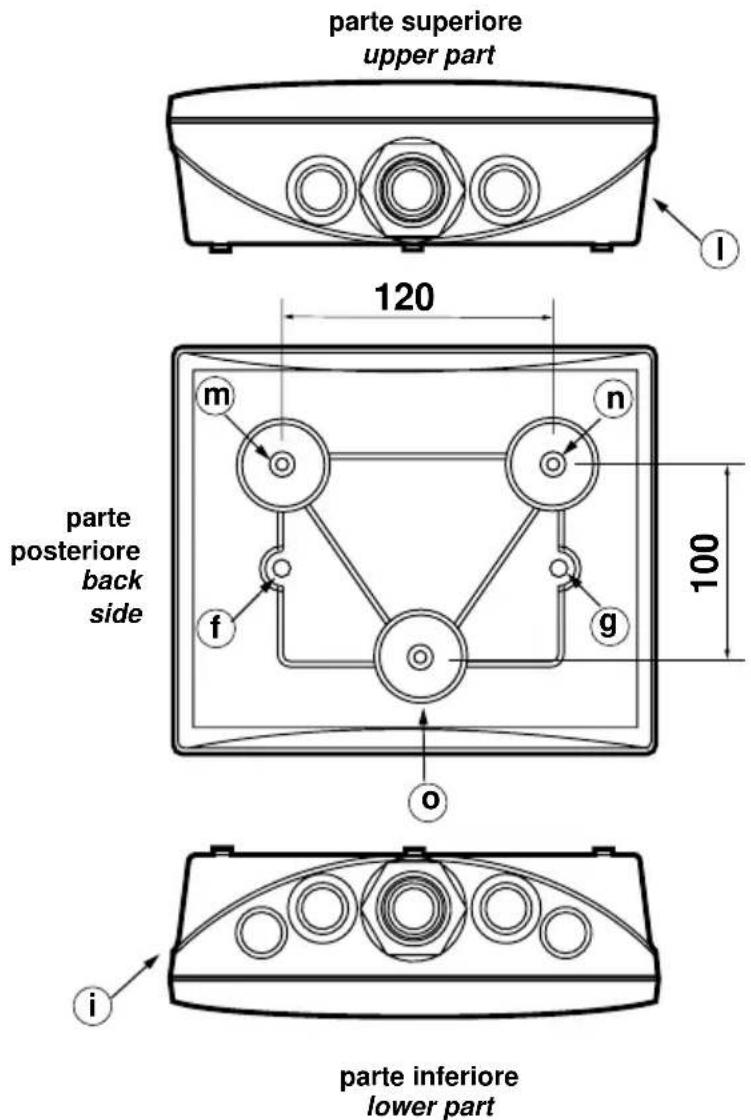
Fig. 1.3.1
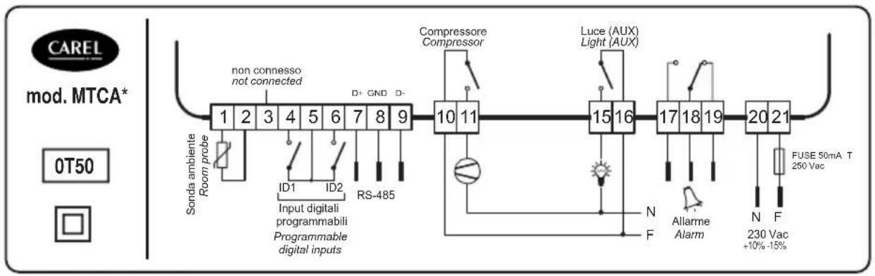
1.4 Electrical connections
See in fig. 1.4.1, the diagrams of the electrical connections
flowchart
graph LR
    A["1"] --> B["2"]
    B --> C["3"]
    C --> D["4"]
    D --> E["5"]
    E --> F["6"]
    F --> G["7"]
    G --> H["8"]
    H --> I["9"]
    I --> J["10"]
    J --> K["11"]
    K --> L["15"]
    L --> M["16"]
    M --> N["17"]
    N --> O["18"]
    O --> P["19"]
    P --> Q["20"]
    Q --> R["21"]

    S["Sonda ambiente Room probe"] --> T["non connesso not connected"]
    U["ID1"] --> V["ID2"] --> W["RS-485"]
    X["Input digitali programmabili Programmable digital inputs"] --> Y["Compressor Compressor"]
    Z["N Allarme Alarm"] --> AA["FUSE 50mA T 250 Vac +10%-15%"]
    AB["N F"] --> AC["230 Vac +10%-15%"]
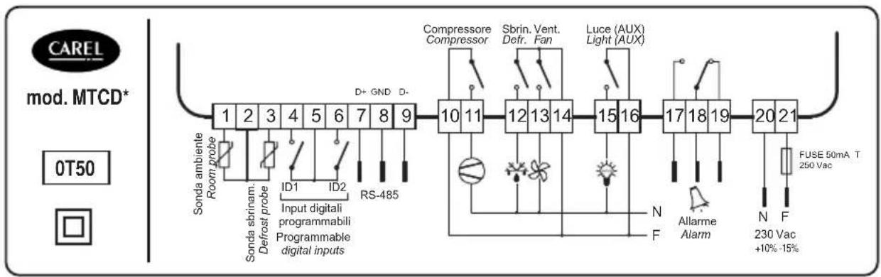
flowchart
graph LR
    A["1"] --> B["Sonda ambiente Room probe"]
    B --> C["Sonda sbrinam. Defrost probe"]
    C --> D["ID1"]
    C --> E["ID2"]
    C --> F["RS-485"]
    D --> G["Input digitali programmabili Programmable digital inputs"]
    E --> G
    F --> G
    G --> H["10 11"]
    H --> I["Compressor Compressor"]
    I --> J["Sbrin. Vent. Defr. Fan"]
    J --> K["Luce (AUX) Light (AUX)"]
    K --> L["12 13 14"]
    L --> M["15 16"]
    M --> N["17 18 19"]
    N --> O["20 21"]
    O --> P["FUSE 50mA T 250 Vac"]
    P --> Q["N Allarme Alarm"]
    Q --> R["N F 230 Vac +10%-15%"]
Fig. 1.4.1
2. Function and description of the buttons
The function buttons feature an easy to use format. In particular, buttons no. 1, 5, 6 (Fig. 2.1) can have more functions, as following described.
① Silences the buzzer, while the alarm code remains as long as the alarm condition remains:
- if pressed when turning On the instrument: allows to restore the default parameters (see section "Alarms, signalling and troubleshooting");
- if pressed for more than 5 seconds: allows access to the frequent parameters selection menu (F);
- if pressed for more than 5 seconds together with the SET button: a llows access to the configuration menu through password 22 (see section "Second level: configuration parameters");
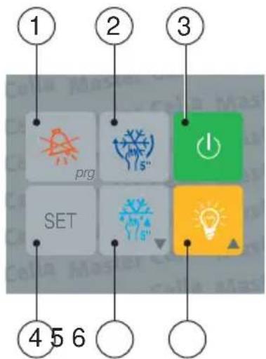
Fig. 2.1
② if pressed for more than 5 seconds: activates/deactivates a continuous cycle, that is the forced activation of the compressor for a period to be selected (see parameter "cc");
③ allows the switching On/Off of the refrigerating unit.
Warning: when the controller is OFF, all outputs, with the exception of the light output and the light button, will be deactivated whereas the On/Off led will be flashing. It is necessary to select the c2 parameter to ensure that, between one switching Off and the following switching On, the minimum time the compressor is Off is maintained. The ON/OFF button can be deactivated: it is sufficient to select one digital input as remote ON/OFF (see "Configuring the digital inputs").
④ selects the Set Point (see "Set Point");
displays the value of the selected parameter (see Modifying and saving the parameters);
- if pressed for more than 5 seconds together with the prg button: allows access to the configuration menu through password 22 (see "Second level: configuration parameters");
⑤ decreases the data value on the display during selection of Set Point and/or parameters;
- if pressed for more than 5 seconds: it forces a manual defrosting cycle;
⑥ activates/deactivates the lights of the cold room (or any other aux. output connected to the 4th relay); increases the displayed value during selection of Set Point and/or parameters.
LED indicators

cooling ON fan evaporator activated


defrosting in progress lights ON


"continuous cycle" functioning unit deactivated (OFF unit)

If a LED flashes, refer to the section "Alarms, signalling and troubleshooting".
3. Operation
3.1 Display
During normal functioning the display shows the value read by the ambient probe. In case of alarm the temperature values will flash alternately with the connected alarm code. When the controller is deactivated (OFF unit) the On/Off led flashes while the display shows the temperature read by the probe.
3.2 Set Point (operating temperature)
- Press for one second the button to visualise the Set Point value;
- after some seconds, the selected value will flash;
- either increase or decrease the Set Point value by pressing the buttons and;
- press the button to confirm the newly set value.
3.3 Manual defrost
Press the button for more than 5 seconds to force a defrosting cycle which will be activated only if the conditions are favourable (for example, the defrost probe should be lower than the selected defrost end temperature. For further information see the technical manual).
3.4 Silencing the buzzer
Pressing the button, besides silencing the buzzer, the alarm relay is reset, while the alarm code remains displayed until the cause of the alarm has been removed.
3.5 Light On/Off
Press the button to activate/deactivate the lights or any other auxiliary output.
3.6 Continuous cycle
To activate the 'continuous cycle' functioning press the button for at least 5 seconds (compressor activated for the time selected with the cc, parameter = duration of continuous cycle).
So as to deactivate the continuous cycle functioning, press the button again for 5 seconds.
4. Parameters
The parameters have been organised into two levels.
4.1 First level: frequent parameters (F)
They are indicated with F in the table and the password is not necessary to gain access to them. To modify them operate as follows:
- press the button for about 5 seconds (in case of alarm, first silence the buzzer);
- the display shows the code of the first parameter to be modified.
To modify the parameters see the Modifying and saving the parameters section.
4.2 Second level: configuration parameters (C)
They are indicated with C in the table and it is necessary to insert the password for any modification, as indicated here below:
- press simultaneously the and buttons for about 5 seconds;
- the display shows 00;
-
press the or button until 22 (password) is displayed;
-
confirm by pressing button;
-
the display shows the code of the first parameter to be modified.
To modify the parameters see the following section, Modifying and saving the parameters.
4.3 Modifying and saving the parameters
4.3.1 Modifying
After having entered the configuration level, to modify a parameter operate as follows:
a. press and/or until the parameter to be modified is displayed (refer to the parameters table);
b. press the button to visualise the value associated to the parameter;
c. modify its value by pressing the 🎨 and/or 🎨” buttons until the desired value is displayed;
d. press the button to tempor ____arily confirm the newly set value and to go back to the param. code display;
e. repeat all operations from the point "press and/or " to modify other parameters values. Per memorizzare passare a "Saving".
4.3.2 Saving
To store the new set values of the parameters:
-
Press the button to store definitively all the new set values and exit the procedure.
-
It is possible to exit without modifying parameters: do not press any button for at least 60 seconds (TIME OUT exit).
-
If the button is not pressed after modifying operations, all the effected variations will be lost, and the starting values will be restored.
4.4 Configuring the digital inputs
Digital inputs ID1 and ID2 can take on different functioning modes according to the value given to the parameter A4 (relative to ID1 input), and to A5 (relative to ID2). The main functions are.
| ValueA4 / A5 | Meaning | Function | |
| 0 | I | nput non active | |
| 1 | I | mmediate external alarm Open Contact = alarm active | |
| 2 | E | xternal alarm with delay Open contact = alarm active. Delay: see parameter A7 | |
| 3 | E | nabling of defrost Open contact = defrost not enabled | |
| 4 | S | tart of defrost Defrost is activated when the contact closes. | |
| 5 | D | oor switch Open contact = open door. When the door is openthe compressor, the evaporator fans and the displaystart to flash; the light is activated and the temperaturealarms are deactivated.After an interval of time that can be selected (d8), thebuzzer begins to sound and the controller start thenormal operation (fan on and compressor on at theoccurance) | |
| 6 | Remote On-Off | Closed contact = ON. This causes the deactivation ofthe button on the frontal part of the instrument.Whenthe control is off, the temperature is displayed, theprotections of the compressor are kept, the LIGHTbutton keeps working. | |
| 7 | C | urtain switch Contact close = curtain down.With r4=3.0 (value(pre-programmed) the Set Point is increased of3 degrees with respect to the used value with opencurtain. If the auxiliary output is used for lightsmanagement, the curtain down switches automaticallyoff the lights while the curtain up switches it on. |
4.4.1 Duty setting selection (parameters c4 and A6)
If the control probe alarm (E0 flashing) is activated, the parameter c4 allows the compressor to function:
- c4=value between 1 and 99: sets the compressor On-time (expressed in minutes), followed by a fixed Off-time equal to 15 min;
- c4=0: compressor always Off;
- c4=100: compressor always On.
If an external alarm (IA or dA flashing) is activated on the digital input (A4=1; A4=2), the parameter A6 allows the compressor to function:
- A6= value between 1 and 99: sets the compressor On-time (expressed in minutes), followed by a fixed Off-time equal to 15 min;
- A6=0: compressor always Off;
- A6=100: compressor always On.
4.5 Table of the parameters
Parameter Type Min Max U.M. Def
| PAPASSWORD C 00 +199 - 22 | ||||||
| / | P | ROBE PARAMETERS | ||||
| /C | Ambient probe calibration F -20 | +20 °C/°F | 0.0 | |||
| /2 | Measurement stability | C 1 | 15 - 4 | |||
| /3 | Probe reading speed | C 1 | 15 - 8 | |||
| /4 | Probes average (see installation manual) | C | 0 | 100 | - | |
| /5 | °C /°F (0=°C, 1=°F) | C | 0 | 1 | flag | |
| /6 | Enabling of decimal point (0=yes, 1=no) | C | 0 | 1 | flag | |
| r | CONTROL PARAMETERS | |||||
| rd | Control differential (hysteresis) | F | 0.1 | +19.9 | °C/°F | |
| r1 | Minimum set allowed | C | -50 | r2 | °C/°F | |
| r2 | Maximum set allowed | C | r1 | +199 | °C/°F | |
| r3 | Enabling of Ed alarm defrost interrupted because max.duration has been reached, param. DP; (0=no, 1=yes) | C | 0 | 1 | flag | |
| r4 | Automatic Set Point variation during night functioning (that iswhen the curtain switch is closed, with either A4 or A5=7) | C | 0 | +20 | °C/°F | |
| r5 | Enabling of min./max. temp. monitoring (0=no, 1=yes) | C | 0 | 1 | flag | |
| rt | Actual interval in max./min. temperature reading | F | 0 | 199 | hours | |
| rH | Maximum temperature read in the rt interval | F | - | - | °C/°F | |
| rL | Minimum temperature read in the rt interval | F | - | - | °C/°F | |
| c COMPRESSOR PARAMETERS | ||||||
| c0 | Compressor start-up delay after unit start-up | C | 0 | 15 | min | |
| c1 | Minimum interval between two compressor start-up | C | 0 | 15 | min | |
| c2 | Minimum compressor off-time | C | 0 | 15 | min | |
| c3 | Minimum compressor on-time | C | 0 | 15 | min | |
| c4 | Relay safety (0=OFF, 100=ON). See Duty setting | C | 0 | 100 | min | |
| cc | Duration of continuous cycle | C | 0 | 15 | hours | |
| c6 | Alarm cut-out after continuous cycle | C | 0 | 15 | hours | |
| d | DEFROST PARAMETERS | |||||
| d0 | Type of defrost (0=heat.,1=hot gas, 2=water/res. time,3=gas time) | C | 0 | 3 | flag | |
| dl | Interval between two defrost phases | F | 0 | 199 | hours | |
| dt | End defrost temperature set | F | -50 | +199 | °C/°F | |
| dP | Maximum duration of defrost or real duration for d0=2 or 3 | F | 1 | 199 | min | |
| d4 | Defrost on unit start-up (0=no,1=yes) | C | 0 | 1 | flag | |
| d5 | Defrost delay after unit start-up or digital input (A4 or A5 =4) | C | 0 | 199 | min | |
| d6 | Display override during defrost (0=no,1=yes) | C | 0 | 1 | flag | |
| dd | Dripping time after defrost | F | 0 | 15 | min | |
| d8 | Duration of alarm cut-out after defrost and,if A4 or A5=5, after door opening | F | 0 | 15 | hours | |
| d9 | Defrost has priority over compressor protection (0=no,1=yes) | C | 0 | 1 | flag | |
| d/ | Defrost temperature probe reading | F | - | - | °C/°F | |
| dC | Time basis (0=hours/min,1=min/s) only for dl and dP | C | 0 | 1 | flag | |
| A | ALARM PARAMETERS | |||||
| A0 | Alarm and fan differential | C | 0.1 | +20 | °C/°F | |
| AL | Low temperature alarm (indicates the max. alloweddeviation from the set-point). AL=0 disabled lowtemperature alarm | F | 0 | +199 | °C/°F | |
A A LARM PARAMETERS
| AH High temperature alarm (indicates the max. allowed F 0 +199 °C/°F 0 deviation from the Set Point). AH=0 disabled high temperature alarm | ||||||
| Ad Temperature alarm delay C 0 199 min 120 | ||||||
| A4 Digital input n.1 configuration C 0 7 - 0 | ||||||
| A5 | Digital input n.2 configuration | C 0 7 - 0 | ||||
| A6 | Cut-out of compressor by external alarm:0=OFF,100=ON. Enabled if either A4 or A5 is 1 or 2.See Duty setting and digital input | C | 0 | 100 | min | 0 |
| A7 | Delay in registration of the input “delayed alarm”(A4 or A5=2) | C | 0 | 199 | min | 0 |
| F | FAN PARAMETERS | |||||
| F0 | Management of fans: 0=always activated except on specific phases (see parameters F2, F3, and Fd)1=controlled by a thermostat according to the difference between ambient temp. and evaporator temperature2=controlled by a thermostat according to the evaporator temperature | C | 0 | 2 | flag | 0 |
| F1 | Fans ON Set-Point: F0=1 fans activated if evap. T. < (ambient T - F1-A0) and OFF if evap. T. > (ambient T. - F1)F0=2 fans ON if evap. T. < (F1-A0); and OFF with evap. T. > F1 | F | -50 | 199 | °C/°F | 5 |
| F2 | Stop fans when compressor is Off (0=no,1=yes). Active if F0=0 | C | 0 | 1 | flag | 1 |
| F3 | Stop fans during defrost (0=no,1=yes).Active for any value of F0 | C | 0 | 1 | flag | 1 |
| Fd | Stop after dripping. Active for any value of F0 | F | 0 | 15 | min | 1 |
| H | OTHER SETTINGS | |||||
| H0 Address within network | C 0 15 | - 1 | ||||
| H1 Selection of relay 4 functioning:0=auxiliary output1=alarm: normally de-energised relay2=alarm: normally energised relay | C 0 1 flag 0 | |||||
| H2 | 0=buttons inhibited; 2=buttons & IR inhibited; 3=IR inhibited | C | 0 | 3 | flag | 1 |
| H3 | Code to enable remote programming | C | 00 | 199 | - | 00 |
| H4 1=disabled buzzer | C 0 1 flag 0 | |||||
Warning:
- for parameters indicated with a grey-shaded background, it is recommended to check before installing if the default values are suitable for the required use.
- for the set times to become operative, the instrument must be switched OFF and ON again.
- on MTCA models the following values have to be assigned to the next parameters:
- r3: must be 0
- d0: 2 or 3 (default: d0= 2)
- dt: irrilevant
- dl: 0.
For a more detailed information on parameters, please refer to the IR32 refrigeration manual (+030220170).
5. Alarms, signalling and troubleshooting
In the following table you can find the most frequent causes for any operation anomaly and some suggested explanations and /or solutions to it.
| Display Cause Check | ||
| Flashing LED | Actuator set delay | Insertion of the relative function is delayed for a period while awaiting an external signal or while held up by another process still in progress. |
| Temperature flashing door open | Door switch broken or | Close the door or check the door switch. |
| Temperature flashing and longer than d8 parameter buzzer ON | Door open for a period of time | Check the door status and the value of the parameter d8 |
| Flashing E0 | Control probe error | Probe not compatible with the equipment; probe cable interrupted or short circuit. Faulty sensor: disconnect the probe from the instrument and measure the resistance (NTC: 0°C=27KΩ). |
| Flashing E1 | Evaporator probe error | Probe not compatible with the equipment; probe cable interrupted or short circuit. Faulty sensor: disconnect the probe from the instrument and measure the resistance (NTC: 0°C=27KΩ). |
| Flashing IA | Alarm from digital input | Check Multi-function inputs and parameters A4 and A5. |
| Flashing dA | Delayed alarm from digital input | Check Multi-function inputs and parameters A4, A5 and A7. |
| Flashing LO | Low temperature alarm (temp. lower than SET - AL - A0) | Check param.s AL, Ad and A0. The alarm will cease as soon as the temp. returns within the limits selected. |
| Flashing HI | High temperature alarm (temp higher than SET + AH + A0) | Check param.s AH, Ad and A0. The alarm will cease as soon as the temp. returns within the limits selected. |
| EA, EB, EE | Data acquisition error. RESET procedure (for mod. MTCA* see point 3 of the Warning chapter 4.5) | In order to restore normal working conditions, reset the default value of the param.s, using this procedure:• turn off the control;• pressing the button and, keeping it pressed, turn on the controller;• the display shows “-c-”; release the PRG button;• after a few seconds, the instrument enters the RESET procedure and allows the modification of parameters;• should EE persist, press the button until the the message disappears. If the error persists, it is necessary to replace the instrument.Any modification made before the reset procedure will be lost |
| Flashing Ed | Defrost end by timeout | • Check parameters dt, dP and d4.• Check if the defrost was done.• if neces. inhibit the Ed alarm through the r3 par. |
| Flashing dF | Defrosting in progress | This is not an alarm signal, but it indic. that the instr. is carrying out a defrost. Appears only if par. d6=0. |
6. Technical specifications
6.1 General characteristics
| operating conditions 0÷50°C, 20÷80% r.H. |
| storage conditions -30÷70°C, 20÷80% r.H. |
| environmental pollution normal |
| period of stress across the insulating parts long |
| PTI of the insulating materials 250V |
| Class of insulation Class II |
| immunity against voltage surges Category 1 |
| index of protection IP65 |
| parameter modification from keypad, from remote control |
| software class and structure Class A |
| display 2 and a half digits |
| category of resistance to fire and heat category D |
| number of automatic operating cycles 100.000 |
| type of action-disconnection 1B |
| signal lights ON, compressor, continuous cycle, defrost, fan, light |
6.2 Electrical specifications
| power supply | 230Vac, +10% -15%, 50/60Hz |
| rated consumption | 7VA |
| terminal block | screw terminals for cables, cross-section: max 1.5mm^2 and min 0.5mm^2 |
Serial connection using MTCSER0000 serial board to Carel RS485 supervisory systems
6.2.1 Inputs
| type | 2 free, not optically-isolated digital contacts (configurable) |
| • cold room temperature probe (Carel NTC 10kΩ at 25°C) | |
| • defrost temperature probe (Carel NTC 10kΩ at 25°C) | |
| measurement (control) interval | -50T50 (-50÷50°C, -58÷+122°F) |
| precision | ±1°C |
| resolution | 0.1°C (0.1°F) between -19.9 and 19.9 |
| 1°C (1 °F) in the rest of the field |
6.2.2 Outputs
If the outputs supply loads other than those described in the table, contact the manufacturer Carel.
| model | MTCA000100 | MTCD000100 | MTCD200100 |
| relay outputs | all with 1B type action, according to ECC EN 60730-1 | ||
| compressor | SPST relay, 8(2)A / 250Vac | SPST relay, 10(10)A / 250Vac | |
| defrost | not available | SPST relay, 10(4)A / 250Vac | |
| fans | not available | SPST relay, 4(2)A / 250Vac | |
| light/aux output | SPST relay, 4(4)A / 250Vac | ||
| alarm output | SPDT relay, 2(2)A / 250Vac | ||
6.3 Mechanical characteristics
mounting panel or wall
containers plastic self-extinguishing (according to UL94-V0)
dimensions (mm) 190x160x65
probe response time in still air (s) 70s
6.4 Dimensions (mm):
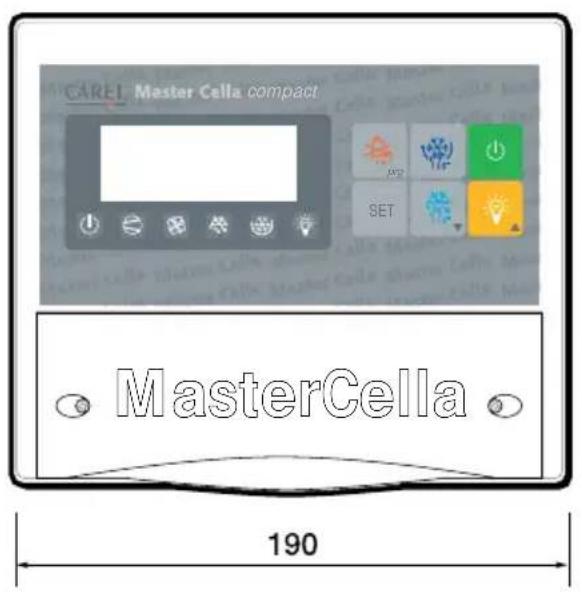
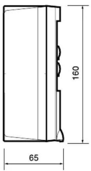
Fig. 6.4.1
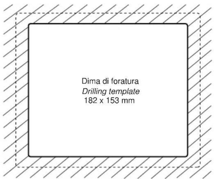
Fig. 6.4.2
Carel reserves the right to modify the features of its products without prior notice.

INSTRUCTIONS IMPORTANTES

AVANT D'INSTALLER OU D'INTERVENIR SUR L'APPAREIL, LIRE ATTENTIVEMENT ET SUIVRE LES INSTRUCTIONS CONTENUES DANS CE MANUEL.
Fig. 1.2.1
1.3 Installation murale
3.5 Allumage/Extinction lumière
A P ARAMETRES D'ALARME
Abb. 1.2.1
1.3 Wandmontage
Fig. 1.1.1
Fig. 1.2.1
Fig. 2.1
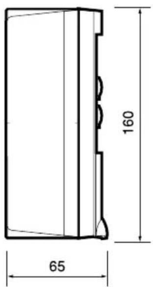
Fig. 6.4.1
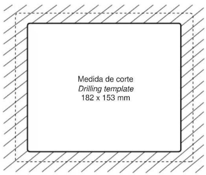
Fig. 6.4.2
- AVVERTENZE IMPORTANTI
- PRIMA DI INSTALLARE O INTERVENIRE SULL'APPARECCHIO, LEGGERE ATTENTAMENTE E SEGUIRE LE ISTRUZIONI CONTENUTE IN QUESTO MANUALE.
- We wish to save you time and money!
- IMPORTANT
- BEFORE INSTALLING OR OPERATING ON THE DEVICE, CAREFULLY READ THE INSTRUCTIONS IN THIS MANUAL.
- Contents
- Introduction 23
- Installation and connections 23
- Function and description of the buttons 27
- Operation 28
- Parameters 29
- Alarms, signals and troubleshooting 33
- Technical specifications 34
- Introduction
- Installation and connections
- General warnings – installation and connection environments
- Advertency. Safety information.
- Panel installation
- Wall-mounted installation
- With reference to Fig. 1.3.1:
- Electrical connections
- Function and description of the buttons
- LED indicators
- Operation
- Display
- Set Point (operating temperature)
- Manual defrost
- Silencing the buzzer
- Light On/Off
- Continuous cycle
- Parameters
- First level: frequent parameters (F)
- Second level: configuration parameters (C)
- Modifying and saving the parameters
- Modifying
- Saving
- Configuring the digital inputs
- Duty setting selection (parameters c4 and A6)
- Table of the parameters
- Warning:
- Alarms, signalling and troubleshooting
- Technical specifications
- General characteristics
- Electrical specifications
- Inputs
- Outputs
- Mechanical characteristics
- Dimensions (mm):
- INSTRUCTIONS IMPORTANTES
- AVANT D'INSTALLER OU D'INTERVENIR SUR L'APPAREIL, LIRE ATTENTIVEMENT ET SUIVRE LES INSTRUCTIONS CONTENUES DANS CE MANUEL.
- Installation murale
- Allumage/Extinction lumière
- Wandmontage
Brand : Carel
Model : MasterCella compact
Category : Temperature regulator