
834832 - Pressure washer SILVERLINE - Free user manual and instructions
Find the device manual for free 834832 SILVERLINE in PDF.

| Product Type | High Pressure Cleaner |
| Brand | Silverline |
| Model | 834832 |
| Supply Voltage | 230-240 V ~ 50 Hz |
| Rated Power | 1400 W |
| Working Pressure | 70 bar |
| Maximum Pressure | 105 bar |
| Working Flow Rate | 5.5 L/min |
| Maximum Flow Rate | 6.8 L/min |
| Inlet Water Temperature Range | 5 - 50 °C |
| Inlet Water Pressure | 0.4 MPa (4 bar) max |
| Protection Class | Class II (double insulation) |
| Protection Rating | IPX5 |
| Dimensions (L x W x H) | 460 x 320 x 250 mm |
| Weight | 7 kg |
| High Pressure Hose Length | Not specified (approx. 5 m estimated) |
| Nozzle Type | Adjustable nozzle (0° to 60°) |
| Detergent Dispenser | Yes, integrated (bottle) |
| Safety | Trigger lock, thermal protection, residual current circuit breaker recommended |
| Maintenance | Clean nozzle with included rod, removable water inlet filter |
| Warranty | 3 years (online registration required within 30 days) |
Frequently Asked Questions - 834832 SILVERLINE
User questions about 834832 SILVERLINE
0 question about this device. Answer the ones you know or ask your own.
Ask a new question about this device
Download the instructions for your Pressure washer in PDF format for free! Find your manual 834832 - SILVERLINE and take your electronic device back in hand. On this page are published all the documents necessary for the use of your device. 834832 by SILVERLINE.
USER MANUAL 834832 SILVERLINE
natural_image
Black silver water leveling station press with coiled hoses and hose (no visible text or symbols)
silverlinetools.com
natural_image
Black industrial water purifier device with attached cable and labeled component (no text or symbols beyond label)
natural_image
Close-up of a black plastic mechanical component with a vertical line above it (no text or symbols visible)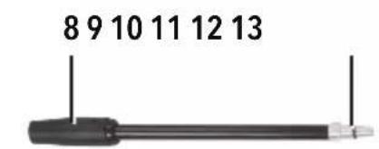
natural_image
Pure electrical circuit lines without any symbols


A
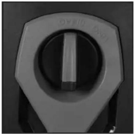
OFF/O ON/I
natural_image
Close-up of a mechanical control knob with no visible text or symbols on the dial (pure technical drawing)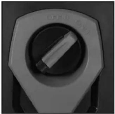
natural_image
Close-up of a metallic switch or knob with a circular dial and central shaft (no visible text or symbols)B
natural_image
Close-up of hands holding a small mechanical component with a string inserted (no visible text or symbols)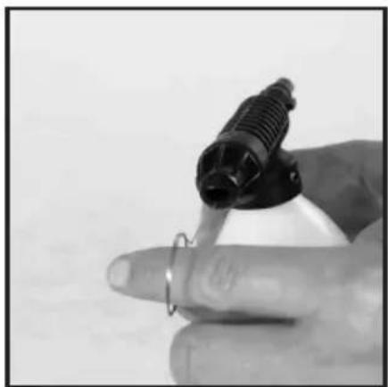
natural_image
Close-up of a hand holding a small object with a ring, possibly a tool or device (no visible text or symbols)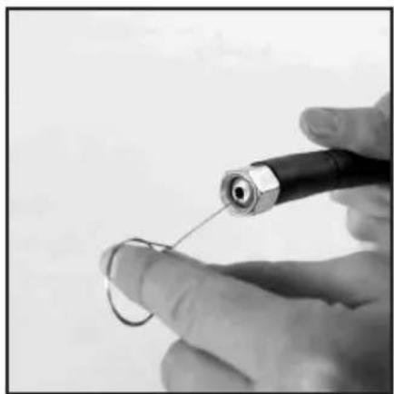
natural_image
Close-up of a hand holding a small wire with a connector, no visible text or symbolsC
natural_image
Close-up of a black electrical plug with three white pin symbols and directional arrows indicating rotation (no text or labels)D

natural_image
Close-up of a black handheld device with a handle and internal frame, showing a mechanical assembly with a close-up inset (no text or symbols visible)Fig. I
natural_image
Illustration of a hand holding a threaded bolt with directional arrows indicating rotation (no text or symbols)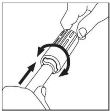
natural_image
Illustration of a hand holding a cylindrical tool with directional arrows indicating rotation or movement (no text or symbols)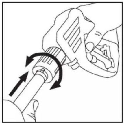
natural_image
Illustration of hands using a tool to adjust a mechanical component with directional arrows (no text or symbols)Fig. II
natural_image
Line drawing of a hand holding a mechanical component with arrows indicating motion (no text or symbols)
natural_image
Line drawing of a car wheel assembly with arrows indicating parts of the component (no text or symbols)Fig. III
natural_image
Line drawing of a car's internal mechanical assembly with a hand operating the shaft (no text or symbols)Fig. IV
natural_image
Line drawing of a hand holding a tool with arrows indicating movement or adjustment (no text or symbols)Fig. V
natural_image
Illustration of a hand holding a threaded connector with an arrow indicating rotation (no text or symbols)Fig. VI
natural_image
Line drawing of a hand inserting a small component into a mechanical housing (no text or symbols)Fig. VII
natural_image
Line drawing of a hand turning a tool with directional arrows indicating rotation (no text or symbols)English ......8
Français ......14
Deutsch......20
Español......26
Italiano ....32
Nederlands ......38
Polski ......44
Introduction
Thank you for purchasing this Silverline tool. This manual contains information necessary for safe and effective operation of this product. This product has unique features and, even if you are familiar with similar products, it is necessary to read this manual carefully to ensure you fully understand the instructions. Ensure all users of the tool read and fully understand this manual.
Description of Symbols
The rating plate on your tool may show symbols. These represent important information about the product or instructions on its use.

Wear hearing protection.
Wear eye protection.
Wear breathing protection.
Wear head protection.

Wear hand protection.

Read instruction manual.

Caution!

Risk of electrocution!

Class II construction (double insulated for additional protection)

According to the applicable regulations, the appliance must never be used on the drinking water supply without a system separator

Conforms to relevant legislation and safety standards

Environmental Protection
Waste electrical products should not be disposed of with household waste. Please recycle where facilities exist. Check with your local authority or retailer for recycling advice
Technical Abbreviations Key
| V Volts | |
| ~,AC Alternating current | |
| A, mA Ampere, milli-Amp | |
| Hz Hertz | |
| W, kW Watt, kilowatt | |
| /min or min ^-1 | Operations per minute |
Specification
Voltage 230-240V\~50Hz
Power....1400W
Working pressure (Bar) 70
Max pressure (Bar)....105
Working flow rate 5.5L/min
Maximum flow rate 6.8L/min
High pressure hose length 5m
Detergent ratio ...... Variable
Inlet water temperature range 5-50°C
Inlet water pressure (Max)....0.4MPa(4bar)
Protection class.
Ingress protection....IPX5
Power cable length....5m
Dimensions (H x L x W) 460 x 320 x 250mm
Weight....7kg
As part of our ongoing product development, specifications of Silverline products may alter without notice.
Sound & vibration information
According to Machinery Directive 2006/42/EC:
Sound pressure I_R ..... 81dB(A)
Sound power L_40 93.42dB(A)
Uncertainty K....3dB
Weighted vibration a _h .......<2.5m/s ^2
According to Outdoor Noise Directive 2000/14/EC:
Guaranteed sound power L 97dB(A)
The sound intensity level for the operator may exceed 85dB(A) and sound protection measure are necessary.
WARNING: Always wear ear protection where the sound level exceeds 85dB(A) and limit the time of exposure if necessary. If sound levels are uncomfortable, even with ear protection, stop using the tool immediately and check the ear protection is correctly fitted and provides the correct level of sound attenuation for the level of sound produced by your tool.
WARNING: User exposure to tool vibration can result in loss of sense of touch, numbness, tingling and reduced ability to grip. Long-term exposure can lead to a chronic condition. If necessary, limit the length of time exposed to vibration and use anti-vibration gloves. Do not operate the tool with hands below a normal comfortable temperature, as vibration will have a greater effect. Use the figures provided in the specification relating to vibration to calculate the duration and frequency of operating the tool.
Sound and vibration levels in the specification are determined according to international standards. The figures represent normal use for the tool in normal working conditions. A poorly maintained, incorrectly assembled, or misused tool, may produce increased levels of noise and vibration.
www.osha.europa.eu provides information on sound and vibration levels in the workplace that
may be useful to domestic users who use tools for long periods of time.
Carefully read and understand this manual and any label attached to the tool before use. Keep these instructions with the product for future reference. Ensure all persons who use this product are fully acquainted with this manual.
Even when used as prescribed it is not possible to eliminate all residual risk factors. Use with caution. If you are at all unsure of the correct and safe manner in which to use this tool, do not attempt to use it.
General Safety
WARNING: Read all safety warnings, instructions, illustrations and specifications provided with this appliance. Failure to follow all instructions listed below may result in electric shock, fire and/or serious injury.
Save all warnings and instructions for future reference.
The term "appliance" in the warnings refers to your mains-operated (corded) appliance or battery-operated (cordless) appliance.
1) Work area safety
a) Keep work area clean and well lit. Cluttered or dark areas invite accidents.
b) Do not operate appliances in explosive atmospheres, such as in the presence of flammable liquids, gases or dust. Appliances create sparks which may ignite the dust or fumes.
c) Keep children and bystanders away while operating an appliance. Distractions can cause you to lose control.
2) Electrical safety
a) Appliance plugs must match the outlet. Never modify the plug in any way. Do not use any adapter plugs with earthed (grounded) appliances. Unmodified plugs and matching outlets will reduce risk of electric shock.
b) Avoid body contact with earthed or grounded surfaces, such as pipes, radiators, ranges and refrigerators. There is an increased risk of electric shock if your body is earthed or grounded.
c) Do not abuse the cord. Never use the cord for carrying, pulling or unplugging the appliance. Keep cord away from heat, oil, sharp edges or moving parts. Damaged or entangled cords increase the risk of electric shock.
d) When operating an appliance outdoors, use an extension cord suitable for outdoor use. Use of a cord suitable for outdoor use reduces the risk of electric shock.
e) If operating an appliance in a damp location is unavoidable, use a residual current device (RCD) protected supply. Use of an RCD reduces the risk of electric shock.
3) Personal safety
a) Stay alert, watch what you are doing and use common sense when operating an appliance. Do not use an appliance while you are tired or under the influence of drugs, alcohol or medication. A moment of inattention while operating appliances may result in serious personal injury.
b) Use personal protective equipment. Always wear eye protection. Protective equipment such as a dust mask, non-skid safety shoes, hard hat or hearing protection used for appropriate conditions will reduce personal injuries.
c) Prevent unintentional starting. Ensure the switch is in the OFF-position before connecting to source and/or battery pack, picking up or carrying the appliance. Carrying appliances with your finger on the switch or energising appliances that have the switch ON invites accidents.
d) Remove any adjusting key or wrench before turning the appliance ON. A wrench or a key left attached to a rotating part of the appliance may result in personal injury.
e) Do not overreach. Keep proper footing and balance at all times. This enables better control of the appliance in unexpected situations.
f) Do not let familiarity gained from frequent use of appliances allow you to become complacent and ignore appliance safety principles. A careless action can cause severe injury within a fraction of a second.
4) Appliance use and care
a) Do not force the appliance. Use the correct appliance for your application. The correct appliance will do the job better and safer at the rate for which it was designed.
b) Do not use the appliance if the switch does not turn it ON and OFF. Any appliance that cannot be controlled with the switch is dangerous and must be repaired.
c) Disconnect the plug from the source and/or remove the battery pack, if detachable, from the appliance before making any adjustments, changing accessories, or storing appliances. Such preventive safety measures reduce the risk of starting the appliance accidentally.
d) Store idle appliances out of the reach of children and do not allow persons unfamiliar with the appliance or these instructions to operate the appliance. Appliances are dangerous in the hands of untrained users.
e) Maintain appliances and accessories. Check for misalignment or binding of moving parts, breakage of parts and any other condition that may affect the appliance's operation. If damaged, have the appliance repaired before use. Many accidents are caused by poorly maintained appliances.
f) Use the appliance, accessories and appliance bits, etc. in accordance with these instructions, taking into account the working conditions and the work to be performed. Use of the appliance for operations different from those intended could result in a hazardous situation.
g) Keep handles and grasping surfaces dry, clean and free from oil and grease. Slippery handles and grasping surfaces do not allow for safe handling and control of the appliance in unexpected situations.
5) Service
a) Have your appliance serviced by a qualified repair person using only identical replacement parts. This will ensure that the safety of the appliance is maintained.
Pressure Washer Safety
- Do not operate this appliance in the rain. Keep all electrical connections dry. Do not allow the machine to become wet. Never allow water to enter ventilation holes
- Always connect a backflow preventer (also called a non-return valve) between pressure washer and potable water mains to prevent a backflow contaminating your water supply. Alternatively, connect the pressure washer to a water butt or other stored water supply
- Do not attempt to use this machine in temperatures below 0^
- Always connect a 'continuous flow' clean water supply to the pressure washer. Running the pressure washer dry, or with dirty water, will cause permanent damage to the pump
- Never connect the pressure washer to a hot water supply; this will cause the pump to malfunction and could result in permanent damage
- Ensure that the water supply to the pressure washer is at a constant pressure. If the water supply is 'shared' by another appliance (e.g. washing machine), ensure that the other appliance is switched OFF
- The pressure washer should always be used in an upright position
- Be aware that the lance will produce a recoil force when the pressure washer is operated. Hold the lance securely
- Never direct the water jet at people or animals. The water jet is extremely powerful, and can cause serious injury. Do not direct the water jet towards the pump body, or other electrical equipment
- Handle the lance with care, do not allow the nozzle to strike the ground. Do not allow the hoses to be twisted, crushed, or strained
- Do not attempt to pressure wash any material suspected to contain asbestos
- When using detergents with pressure washers or cleaning oil and grease from surfaces, take responsibility for any contaminated waste water you may produce. Always consider the environment and the risk of polluting streams and other watercourses, plus the possibility of contaminants accumulating in the ground and soil. Try to use detergents sparingly—they are not always necessary. Contact your local environmental agency for how to deal with such waste water legally and responsibly
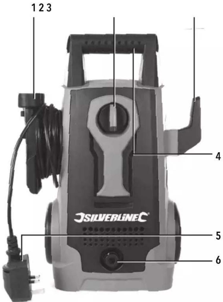
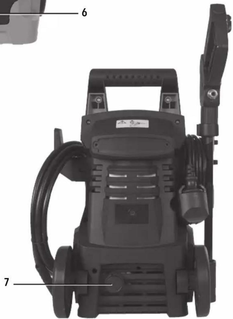
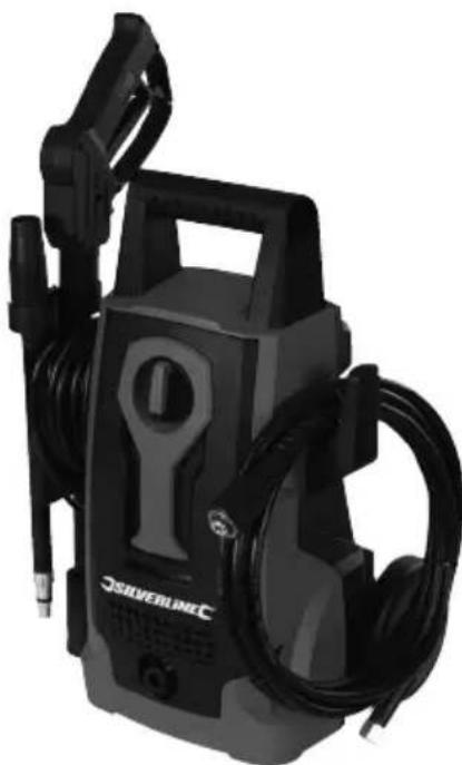
Product Familiarisation
- Lance bracket / Power Cord Hook
- ON/OFF Switch
- Hose Bracket
- Handle
- Power Cord
- High Pressure Water Outlet
- Water Inlet
- Nozzle
- Nozzle Bayonet Connector
- Lance Extension Socket
- Lance Extension Bayonet Connector
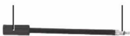
- Lance Handle Bayonet Socket
- Lance High Pressure Hose Connector
- Lance Handle Grip
- Trigger Lock
- Trigger
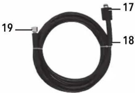
- Hose Connector (Pressure Washer Unit)
- High Pressure Hose
- Hose Connector (Handle)
- Cleaning Pin
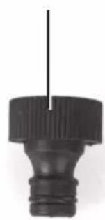
- Inlet Hose Connector
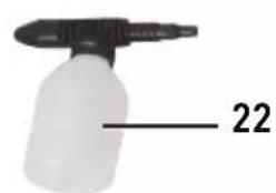
- Lance Detergent Dispenser
- Cleaning Pin Bracket
Intended Use
Pressure washer for general, light to medium duty cleaning tasks on vehicles, buildings and other suitable surfaces, using a jet of cold, pressurised water, with or without detergent.
Unpacking Your Tool
- Carefully unpack and inspect your product. Fully familiarise yourself with all its features and functions
- Ensure that all parts of the product are present and in good condition. If any parts are missing or damaged, have such parts replaced before attempting to use this product
Before Use
• Always check all parts and attachments are secure, and that hoses are not kinked or obstructed
- Always wear appropriate personal protective equipment for the job at hand. Use of this appliance requires safety goggles and waterproof clothing
- Always use an RCD when connecting a pressure washer to the mains with a tripping current of no more than 30mA, and a delay in operating of no more than 30ms
- Make sure mains connection points are out of reach of the pressure washer water spray and any water that may collect on surrounding surfaces
- Only use a mains extension cable suitable for outdoor use and capable of carrying the required current for this product. The cable must be protected against water ingress and maintain water-tight connections where it connects to the pressure washer
- This product must be earthed and any extension cables used must have an earth connection
• Always use the pressure washer vertically and make sure it is used on a flat, level surface
Assembly
- Do not connect the pressure washer to the water or electrical supply until fully assembled and ready for use
- Remove all packaging materials from the product
- Attach Lance Bracket / Power Cord Hook (1) to main assembly sliding it down until it clicks securely into place (Fig. VI)
Lance
- To assemble the Lance, insert Lance Extension Bayonet Connector (11) into Lance Handle Bayonet Socket (12) then rotate and release so the bayonet connector is locked in the groove of the bayonet socket (Fig. I)
- Attach the Nozzle Bayonet Connector (9) to Lance Extension Socket (10) by repeating the above process (Fig. I)
Notes:
- If using the Lance Detergent Dispenser (22) fit to the Lance Extension Socket (10) instead of the Nozzle Bayonet Connector (9) (Fig. 1)
- Do not attempt to fit the Nozzle Bayonet Connector (9) or Lance Detergent Dispenser (22) directly into the Lance Handle Bayonet Socket (12). The fittings are a different size
High pressure hose
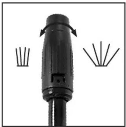
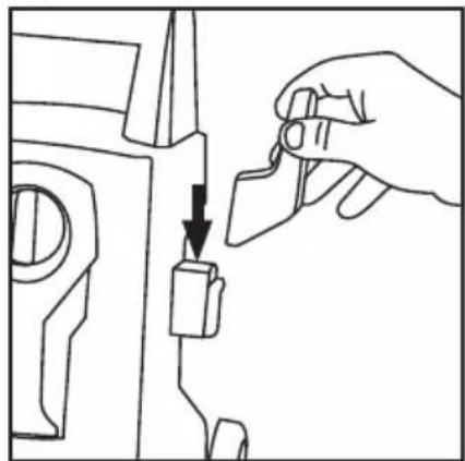
- Remove the plastic cap from the Hose Connector (Handle) (19) if fitted (Fig. II)
- Carefully cut and remove cable ties around the hose (making sure not to damage the hose surface), then uncoil hose
- Attach the Hose Connector (Handle) (19) to the Lance High Pressure Hose Connector (13) (Fig. IV), then screw the fittings together until tight
- Remove the plastic cap from the High Pressure Water Outlet (6) (Fig. II)
- Attach the Hose Connector (17) to the High Pressure Water Outlet (6), and screw the fittings together until tight (Fig. VII)
WARNING: If the high pressure hose is damaged it can burst and cause injury. A damaged hose must be replaced, not repaired. Inspect regularly and prevent the hose from coming into contact with sharp objects or rough surfaces.
Connecting to water supply
WARNING: When connecting a pressure washer to a normal domestic water supply, ensure a non-return valve is fitted to the hose (also called backflow preventer). This will prevent the pressure washer contaminating the water supply if there is a backflow.
- Remove the plastic cap from the Water Inlet (7) (Fig. II)
- Check the filter inside the water inlet is clear of debris or any other material. Over time debris may build up and the filter will need to be checked regularly and any debris build-up removed
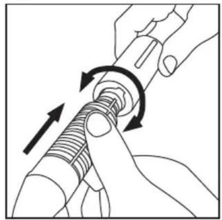
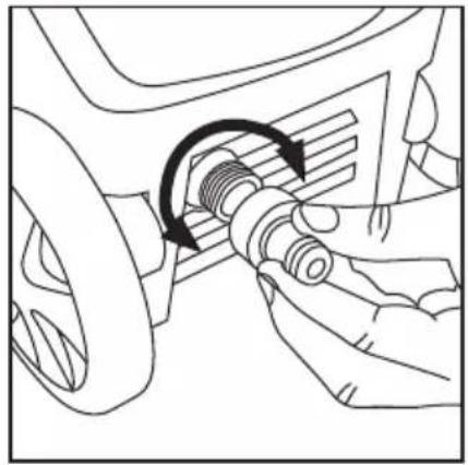
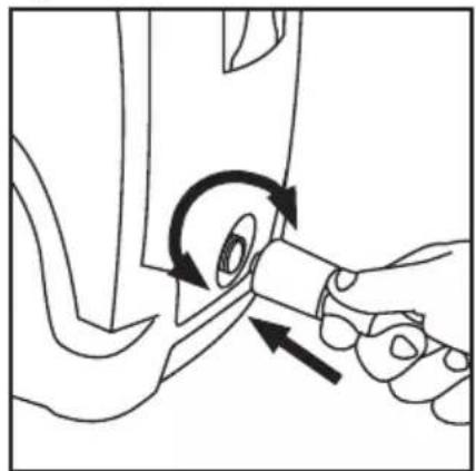
- Fit the Inlet Hose Connector (21) to Water Inlet (7) and tighten by hand only (Fig. III)
- Connect a hose from the water supply to the Inlet Hose Connector (21)
Notes:
- The specification lists suitable water inlet pressures. Do not exceed the maximum water pressure stated in the specification
- If you do not know or are unable to measure the water pressure, keep the pressure low to prevent damage to the pressure washer. Aim to set the pressure at mid-point between the lowest and highest water pressure accepted by the pressure washer. If preferred, a third party water pressure gauge is available that connects directly to the tap. This will allow the water pressure to be set more accurately
- Do not connect to a hot water supply. This will prevent the pump from cooling and may damage the seals over time
- It is important that a good water connection is maintained while operating a pressure washer, as the pump will be damaged if run without water. Make sure the connections are secure before turning ON the pressure washer
Connecting to other water sources
Note: The pump featured in this pressure washer features a self-priming feature that allows use of other water sources typically a water butt or other container of captured rain water or similar.
- Ensure the water supply is clean and filtered before entering the pressure washer. Ensure there is no sediment
- For water butts, where the output is at the bottom, gravity will provide some pressure to assist the pressure washer
The hose to the water supply should not exceed 3m in length and the diameter should not be less than 19mm or 34 "
Operation
Switching ON
IMPORTANT: Always open the water supply tap before switching ON the pressure washer to protect the pump from damage
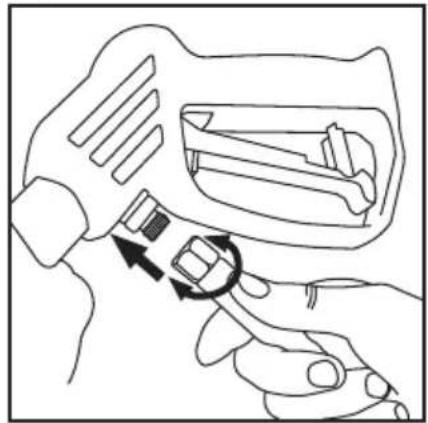
- Set the Trigger Lock (15) to prevent the Trigger (16) being pressed (Image D)
- Connect the pressure washer to the mains supply and switch the ON/OFF Switch (2) ON (Image A). The pump will operate immediately to build up pressure automatically
Note: The water pressure will restore automatically each time the trigger is pressed.
IMPORTANT: Ensure all the air is bled from the hoses and lance before using the pressure washer. Disable the Trigger Lock (15) and squeeze and hold the trigger until water is sprayed in a steady stream. This may take up to 2 minutes or possibly longer on first use (Image D)
Using your pressure washer
WARNING: Do not run the pressure washer continuously for longer than 1 minute. Use more frequent shorter sweeping bursts.
- To spray water, squeeze the Trigger (16). Make sure you are holding the lance securely as there will be a small recoil action when started. The Trigger (16) allows for some adjustment of spray power, depending on how far the trigger is depressed
- To disable the Trigger (16), use the Trigger Lock (15) when necessary (Image D)
Notes:
- The Lance Nozzle (8) can be adjusted between a wide fan pattern (60° spray angle), and a strong narrow jet (0°) (Image C). It is advisable to start with the nozzle turned clockwise (fan pattern), and experiment with narrower patterns, and different spray distances, until the correct strength is achieved. Release the trigger when changing setting
- If you are unsure of the durability of the surface that is being cleaned, avoid using the narrow jet setting and start at a longer distance to the surface
- It is recommended the lance is held at an angle of 45^ to the surface being cleaned. This will give maximum control, and most effective cleaning
WARNING: Always test-clean an inconspicuous area first to check that the cleaning process or detergent will not damage the surface being cleaned, particularly mortar between bricks or patio slabs, which can be easily removed with a water jet
WARNING: Do not press the trigger for longer than 1 minute as the pump may become excessively hot. Always allow some off time as you work and don't waste water on surfaces that do not require cleaning. This machine is fitted with an automatic thermal cut-out and if the pump overheats it will stop. The system will automatically reset after cooling for a few minutes. Always try to work in a way that avoids the thermal cut-out from operating by giving the pump time to cool when possible
Using the detergent dispenser
- When changing accessories, switch OFF the pressure washer, turn OFF the water supply and squeeze the trigger to release pressure (Image A)
- Remove the Nozzle (8) if fitted
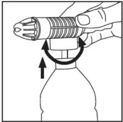
- Fit the Lance Detergent Dispenser (22) to the Lance Extension Socket (10)
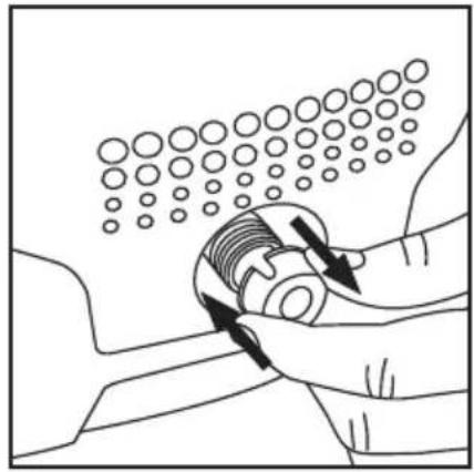
- Remove the dispenser bottle and fill with suitable pressure washer detergent or car shampoo, then re-fit (Fig. V)
- Use the pressure washer as per normal operation to dispense foam as required. The Trigger (16) will control how much foam is dispensed. There are no adjustments on the detergent dispenser
- Use all detergent, ensuring water runs clear and is foam-free at end of use
Notes:
- A typical pattern of use for using detergent foam would be to first clean the surface with water to remove light surface deposits, then apply detergent foam and finally, rinse off with clean water
- Detergent foam requires a few minutes to work when applied. For maximum cleaning, leave 2-5 minutes between applying the foam and removing with clean water - this is an ideal opportunity to brush/scrub the surface where most dirt has collected. Do not allow foam to dry on the surface, for instance, on a hot day, when there may be limited time between dispensing foam and rinsing off, depending on the surface
- Do not use detergents which are not designed for use with pressure washers. They may contain chemicals that could damage seals
- The detergent dispenser is only suitable for detergents with a viscosity close to that of water. If necessary, dilute detergent before filling the detergent dispenser. This pressure washer has an approximate detergent ratio of 1/19th or 95% water to 5% detergent in use. Read the instructions provided with the detergent thoroughly - especially if concentrated. Diluting to the detergent manufacturer's recommendations will ensure effective cleaning without using excessive detergent
Switching OFF
When you have finished using the machine, always carry out the following steps:
- Switch OFF the machine and disconnect from the mains supply (Image A)
- Turn OFF the water supply
- Squeeze the trigger and allow all residual water pressure to bleed
- Disconnect the water supply
- Drain all water from the machine and hoses, and store in a dry place
WARNING: Do not switch OFF the water supply before turning OFF the pump as the pump must not be run without water.
Accessories
A range of accessories is available from your Silverline stockist to enhance the functionality of your pressure washer, including brushes and replacement, or higher specification parts.
Maintenance
Cleaning
- Keep your machine clean at all times
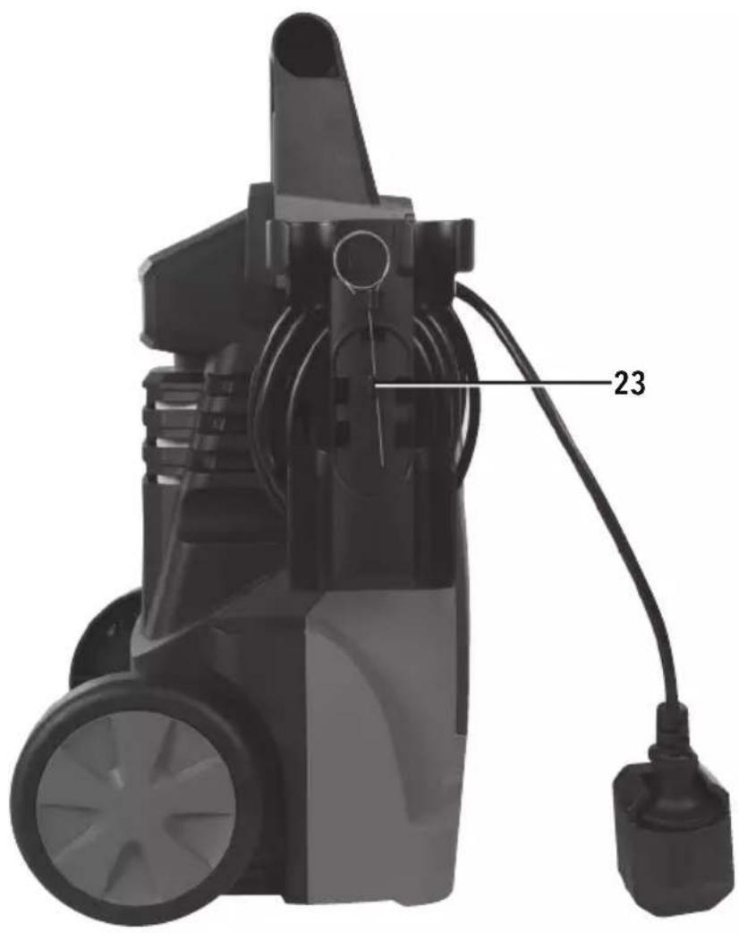
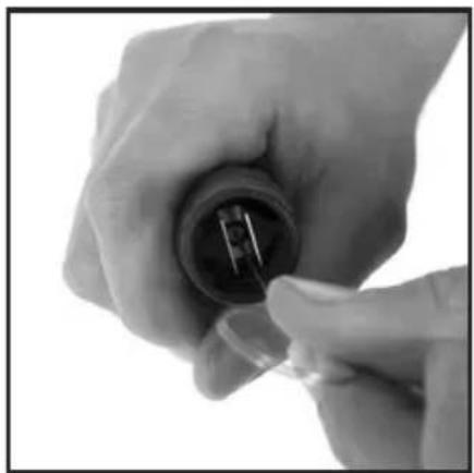
• Always allow all water to drain from the pump before storing - The Nozzle (8) Lance Detergent Dispenser (22) and Lance Extension (10) may get dirty or blocked over time, which will effect operation. Clean using the Cleaning Pin (20) supplied (Image B).
• The Cleaning Pin (20) can be stored in the Cleaning Pin Bracket (23) - A garden hose can also be used to clean the Lance components by back-flushing water through. Combining use of the pin and back-flushing should allow the components to be thoroughly cleaned. The frequency of carrying out this task will depend on the water quality in your area. Hard water areas require more frequent cleaning
- Regularly check the Inlet Hose Connector filter to make sure it is clear. This filter must be checked regularly to ensure it is clear from debris and other materials. Remove the Inlet Hose Connector (21) to access the filter
Brushes
• Over time the carbon brushes inside the motor may become worn
- Excessively worn brushes may cause loss of power, intermittent failure, or visible sparking
- If you suspect that the brushes may be worn, have them replaced at an authorised Silverline service centre
Storage
• Always store this machine in a dry place that will not fall below 0°C
- Ensure all inlets / outlets are capped if not connected to prevent foreign objects entering the appliance when not in use
Disposal
Always adhere to national regulations when disposing of appliances that are no longer functional and are not viable for repair.
- Do not dispose of appliances, or other waste electrical and electronic equipment (WEEE), with household waste
- Contact your local waste disposal authority for information on the correct way to dispose of appliances
Troubleshooting
| Problem Possible cause Solution | ||
| No detergent suction Blockage in detergent bottle tube Clean with warm water | ||
| Smoke | Overload or damaged motor | DO NOT USE. Contact dealer or authorised Silverline service centre immediately |
| Pressure washer doesn't start | Pressurised Squeeze trigger on gun before starting | |
| Mains plug not fully inserted or mains socket is switched OFF | Check and correct issues | |
| RCD has operated or not been reset Reset RCD | ||
| Plug fuse has blown Replace fuse and contact dealer if it blows again immediately | ||
| Thermal safety switch has operated | Switch OFF and allow pressure washer motor to cool before starting | |
| Poor water spray pressure | Water inlet filter is clogged Clean filter | |
| Water hose connection is leaking or allowing air to enter Check water hose connection | ||
| Pressure washer valves or seals are worn or damaged | Contact dealer or authorised Silverline service centre immediately | |
| Clogged nozzle See 'Maintenance' for cleaning procedure | ||
| Motor stops suddenly | Thermal safety switch has operated | Switch OFF and allow to cool before restarting |
| Water leaking from pump | Seals worn out | Contact dealer or authorised Silverline service centre immediately |
Silverline Tools Guarantee
This Silverline product comes with a 3 year guarantee
Register this product at www.silverlinetools.com within 30 days of purchase in order to qualify for the 3 year guarantee. Guarantee period begins according to the date of purchase on your sales receipt.
Registering your purchase
Registration is made at silverlinetools.com by selecting the Guarantee Registration button. You will need to enter:-
- Your personal details
• Details of the product and purchase information
Once this information is entered your guarantee certificate will be created in PDF format for you to print out and keep with your purchase.
Terms & Conditions
Guarantee period becomes effective from the date of retail purchase as detailed on your sales receipt.
PLEASE KEEP YOUR SALES RECEIPT
If this product develops a fault within 30 days of purchase, return it to the stockist where it was purchased, with your receipt, stating details of the fault. You will receive a replacement or refund.
If this product develops a fault after the 30 day period, return it to:
Silverline Tools Service Centre
PO Box 2988
Yeovil
BA21 1WU, UK
The guarantee claim must be submitted during the guarantee period.
You must provide the original sales receipt indicating the purchase date, your name, address and place of purchase before any work can be carried out.
You must provide precise details of the fault requiring correction.
Claims made within the guarantee period will be verified by Silverline Tools to establish if the deficiencies are related to material or manufacturing of the product.
Carriage will not be refunded. Items for return must be in a suitably clean and safe state for repair, and should be packaged carefully to prevent damage or injury during transportation. We may reject unsuitable or unsafe deliveries.
All work will be carried out by Silverline Tools or its authorized repair agents.
The repair or replacement of the product will not extend the period of guarantee
Defects recognised by us as being covered by the guarantee shall be corrected by means of repair of the tool, free of charge (excluding carriage charges) or by replacement with a tool in perfect working order.
Retained tools, or parts, for which a replacement has been issued, will become the property of Silverline Tools.
The repair or replacement of your product under guarantee provides benefits which are additional to and do not affect your statutory rights as a consumer.
What is covered:
The repair of the product, if it can be verified to the satisfaction of Silverline Tools that the deficiencies were due to faulty materials or workmanship within the guarantee period.
If any part is no longer available or out of manufacture, Silverline Tools will replace it with a functional replacement part.
Use of this product in the EU.
What is not covered:
Silverline Tools does not guarantee repairs required as a result of:
Normal wear and tear caused by use in accordance with the operating instructions eg blades, brushes, belts, bulbs, batteries etc.
The replacement of any provided accessories drill bits, blades, sanding sheets, cutting discs and other related items.
Accidental damage, faults caused by negligent use or care, misuse, neglect, careless operation or handling of the product.
Use of the product for anything other than normal domestic purposes.
Change or modification of the product in any way.
Use of parts and accessories which are not genuine Silverline Tools components.
Faulty installation (except installed by Silverline Tools).
Repairs or alterations carried out by parties other than Silverline Tools or its authorized repair agents.
Claims other than the right to correction of faults on the tool named in these guarantee conditions are not covered by the guarantee.
CE Declaration of Conformity
The undersigned: Mr Darrell Morris
as authorised by: Silverline Tools
Declares that
This declaration has been issued under the sole responsibility of the manufacturer.
The object of the declaration is in conformity with the relevant Union harmonisation Legislation.
Identification code: 834832
Description: 1400W Pressure Washer
Conforms to the following directives and standards:
• Machinery Directive 2006/42/EC
• EMC Directive 2014/30/EU
• RoHS Directive 2011/65/EU
• Outdoor Noise Directive 2000/14/EC
• EN 60335-1:2012+A11:2014
Applied Conformity Evaluation Method
2000/14/EC: Annex III
Sound Power Level dB (A)
Measured: 93.42
Guaranteed: 97
Notified body: SGS
The technical documentation is kept by: Silverline Tools
Date: 21/04/2017
Signed:

Mr Darrell Morris
Managing Director
Name and address of the manufacturer:
Powerbox International Limited, Company No. 06897059. Registered address:
Powerbox, Boundary Way, Lufton Trading Estate, Yeovil, Somerset BA22 8HZ, United Kingdom.
Introduction
Silverline Tools Service Centre
PO Box 2988
Yeovil
Silverline Tools Service Centre
PO Box 2988
Yeovil
BA21 1WU, GB
Max waterstroming 6.8 L/min
Silverline Tools Service Centre
PO Box 2988
Yeovil
BA21 1WU, GB
Silverline Tools Service Centre
PO Box 2988
Yeovil
BA21 1WU, UK
Powerbox International Limited, Company No. 06897059. Registered address: Powerbox, Boundary
Way, Lufton Trading Estate, Yeovil, Somerset BA22 8HZ, United Kingdom.
Notes:
Notes:
natural_image
Black industrial water purifier with attached hoses and a brand logo (no visible text or symbols on body)GB 3 Year Guarantee. Register online within 30 days. Terms and Conditions apply.
- Introduction
- Description of Symbols
- Specification
- Sound & vibration information
- According to Outdoor Noise Directive 2000/14/EC:
- General Safety
- Pressure Washer Safety
- Product Familiarisation
- Intended Use
- Unpacking Your Tool
- Before Use
- Assembly
- Lance
- Notes:
- High pressure hose
- Connecting to water supply
- Connecting to other water sources
- Operation
- Switching ON
- Using your pressure washer
- Using the detergent dispenser
- Switching OFF
- Accessories
- Maintenance
- Cleaning
- Brushes
- Storage
- Disposal
- Silverline Tools Guarantee
- This Silverline product comes with a 3 year guarantee
- Registering your purchase
- Terms & Conditions
- PLEASE KEEP YOUR SALES RECEIPT
- Silverline Tools Service Centre
- PO Box 2988
- Yeovil
- BA21 1WU, UK
- What is covered:
- What is not covered:
- CE Declaration of Conformity
- BA21 1WU, GB
Brand : SILVERLINE
Model : 834832
Category : Pressure washer