
41910HTO - Video extender Leviton - Free user manual and instructions
Find the device manual for free 41910HTO Leviton in PDF.

User questions about 41910HTO Leviton
0 question about this device. Answer the ones you know or ask your own.
Ask a new question about this device
Download the instructions for your Video extender in PDF format for free! Find your manual 41910HTO - Leviton and take your electronic device back in hand. On this page are published all the documents necessary for the use of your device. 41910HTO by Leviton.
USER MANUAL 41910HTO Leviton
- Read and understand all instructions. Follow all warning and instructions marked on the product.
- Do not use this product near water-e.g., near a tub, wash basin, kitchen sink or laundry tub, in a wet basement, or near a swimming pool.
- Never push objects of any kind into this product through openings, as they may touch dangerous voltages.
- SAVE THESE INSTRUCTIONS.
SAFETY INFORMATION
- Never install communications wiring or components during a lightning storm.
- Never install communications components in wet locations unless the components are designed specifically for use in wet locations.
- Never touch uninsulated wires or terminals unless the wiring has been disconnected at the network interface.
- Use caution when installing or modifying communications wiring or components.
Contents
- Introduction......4
1.1 Introduction to the 41910-HT0....4
1.2 Features .... 4
1.3 Package Contents ....4
- Product Exterior....5
2.1 41910-HT0 Transmitter....5
2.2 41910-HT0 Receiver ....6
- System Connection....7
3.1 System Diagram....7
3.2 Connection Procedure....7
3.3 Twisted Pair Cable Connection....7
- Specification 8
- Troubleshooting & Maintenance ....8
- Warranty ....8
1. Introduction
1.1 Introduction to the 41910-HT0
The 41910-HT0 sends HDMI™, IR, and RS232 over twisted pair cabling and includes a transmitter and receiver. The 41910-HT0 uses HDBaseT™ technology and has a max transmission distance up to 70 meters with CAT6A cable. Consumer Electronics Control (CEC), bi-directional RS232, IR pass-through, and Power over HDBaseT (PoH) are supported by the 41910-HT0.
1.2 Features
● Supports VESA resolutions up to 1920x1200@60Hz
● Supports HDTV resolutions including 720p, 1080p, 2160p
- Supports 3D
● Max transmission distance is up to 70 meters over single CAT6A cable.
● High Bandwidth: 10.2Gps.
- HDTV Compatible; uses HDMI 1.4 and is HDCP compliant.
● Supports PoH for powering devices from either end
- CEC, EDID and HDCP pass through
- HDBaseT certified
● Bi-directional RS232 and IR pass-through
● Wall or table mountable aluminum enclosure
- Locking input power connector & HDMI connector
1.3 Package Contents
➢ 1 x 41910-HT0 Transmitter (Not in 41910-HTR)
1 x 41910-HT0 Receiver
▶ 4 x Mounting brackets
8 x Rubber feet
2 x RS232 cables
8 x Screws
➢ 1 x Power adapter (DC 24V)
1 x User manual
2. Product Exterior
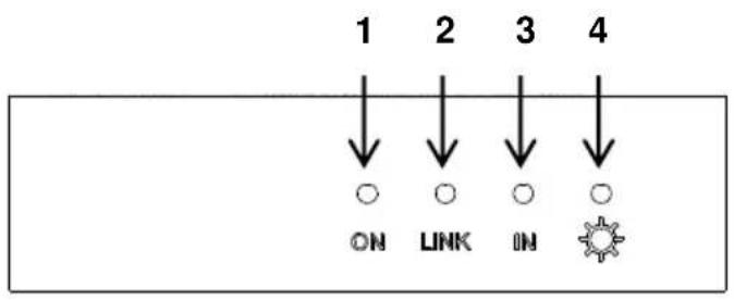
2.1 41910-HT0 Transmitter
text_image
1 2 3 4 ON LINK ON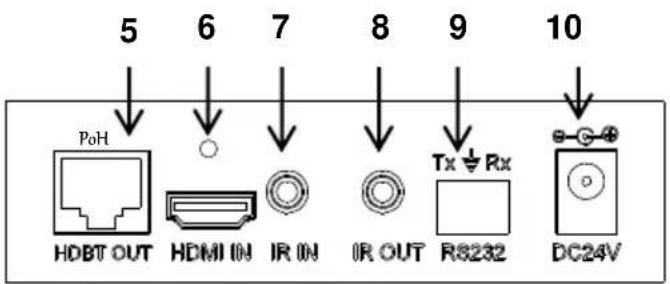
text_image
5 6 7 8 9 10 PoH HDBT OUT HDMI IN IR IN IR OUT Tx ⊕ Rx R8232 DC24V1) ON: Blinks green when the device is operational; turns off when the device stops working.
2) LINK: Twisted Pair cable link status indicator, illuminates green when the connection between the transmitter and receiver is successful.
3) IN: HDCP compliance indicator, solid green when the connected device supports HDCP and works normally; blinks green when the connected device does not support HDCP.
4) POWER LED: Illuminates red when the power is on.
5) HDBT OUT: Connect to the HDBT IN port of an HDBaseT certified receiver with a twisted pair cable.
6) HDMI IN: Connect to HDMI source.
a) Threaded insert for locking connector is M3 - 0.5mm (kit sold separately 41900-LKT)
7) IR IN: Connect with an IR target (sold separated 41910-HIR)
8) IR OUT: Connect with an IR emitter (sold separately 41910-HIR)
9) RS232: Serial pass through
10) DC 24V: Connect with the included power supply (can be placed at transmit or receive end).
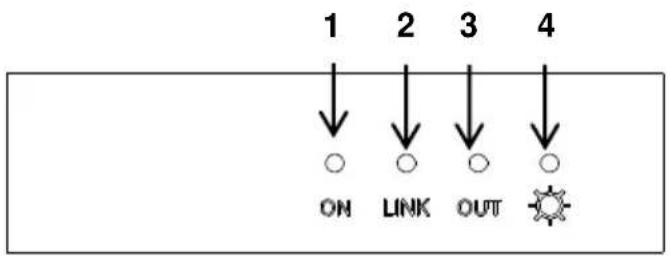
2.2 41910-HT0 Receiver
text_image
1 2 3 4 ON LINK OUT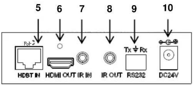
text_image
5 6 7 8 9 10 PoT HDBT IN HDMI OUT IR IN IR OUT Tx ⊥ Rx RS232 DC24V1) ON: Blinks green when the device is operational; turns off when the device stops working.
2) LINK: Twisted Pair link status indicator, illuminates green when the connection between the two devices is successful.
3) OUT: HDCP compliance indicator, illuminates green when the connected device supports HDCP and works normally; blinks green when the connected device does not support HDCP.
4) POWER LED: Illuminates red when the power is on.
5) HDBT IN: Connect to the HDBT OUT port of an HDBaseT certified transmitter with a twisted pair cable.
6) HDMI OUT: Connect to an HDMI display device.
a) Threaded insert for locking connector is M3 - 0.5mm (kit sold separately 41900-LKT)
7) IR IN: Connect with an IR target (sold separately 41910-HIR).
8) IR OUT: Connect with an IR emitter (sold separately 41910-HIR).
9) RS232: Serial pass-through
10) DC 24V: Connect with the included power supply (can be placed at transmit or receive end).
3. System Connection
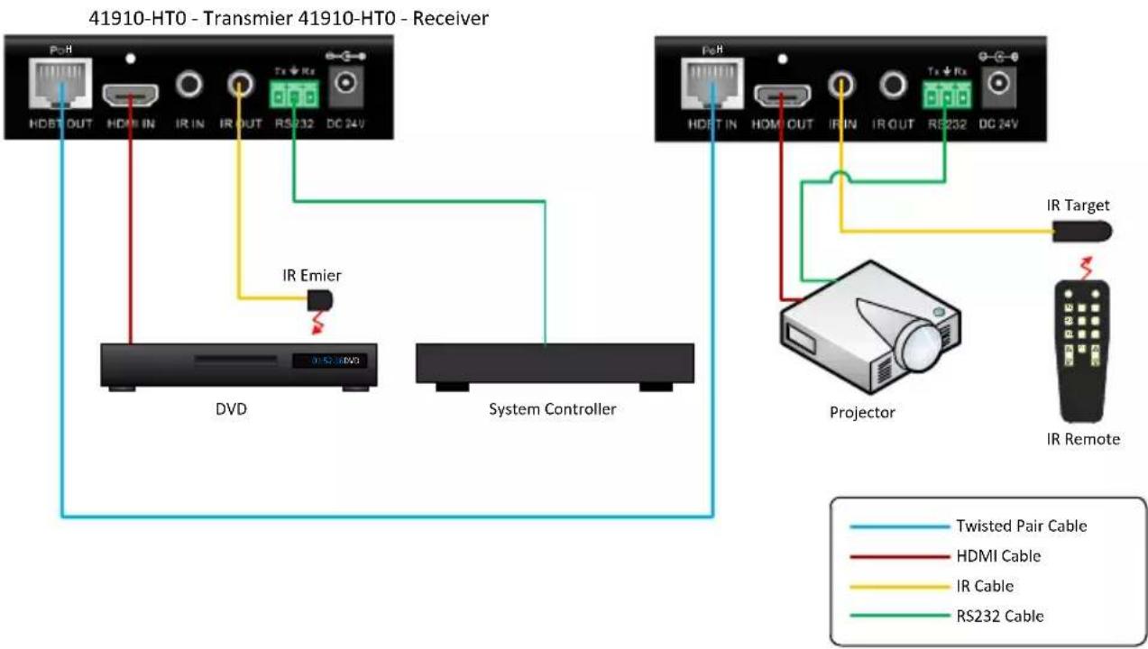
3.1 System Diagram
flowchart
graph TD
    A["41910-HT0 - Transmier 41910-HT0 - Receiver"] --> B["HDBT OUT HDM IN IR IN IR OUT RS232 DC 24V"]
    B --> C["IR Emier"]
    C --> D["DVD"]
    C --> E["System Controller"]
    F["41910-HT0 - Transmier 41910-HT0 - Receiver"] --> G["HDBT IN HDM OUT IR IN IR OUT RS232 DC 24V"]
    G --> H["IR Target"]
    H --> I["Projector"]
    I --> J["IR Remote"]
    style A fill:#f9f,stroke:#333
    style F fill:#f9f,stroke:#333
    style I fill:#ccf,stroke:#333
3.2 Connection Procedure
Step1. Connect an HDMI source (such as a Blu-ray or DVD player) to the HDMI IN port of the 41910-HT0 Transmitter with an HDMI cable.
Step2. Connect the HDBT OUT port of the 41910-HT0 Transmitter to the HDBT IN port of 41910-HT0 Receiver through a CAT 6A cable.
Step3. Connect an HDMI display (such as an HDTV) to the HDMI OUT port of the 41910-HT0 Receiver with an HDMI cable.
Step4. Both the 41910-HT0 Transmitter and the 41910-HT0 Receiver have IR IN and OUT. When one end is used as an IR target, the other end will be used as an IR emitter (sold separately 41910-HIR).
Step5. Connect the RS232 port to a system controller and controlled device as required.
Step6. Connect the DC 24V power adaptor (one is sufficient as the other end can be energized via the PoH function).
3.3 Twisted Pair Cable Connection
For best performance, twisted pair cable should be installed in accordance with TIA-568-C.0 and NEC 300 and field certified using ANSI/TIA-568 UL approved testers.
4. Specification
| General | |
| Resolution | VESA up to 1920x1200@60HzHDTV 720p@60Hz, 1080p@60Hz, 2160p@30Hz |
| Transmission Distance | Max distance 70M |
| HDMI Standard | Supports HDMI1.4 and HDCP |
| Temperature | -10 ~ +40°C |
| Humidity | 10% ~ 90% |
| Power Supply | Input: 100VAC~240VAC, 50/60Hz Output: DC 24V, 1.25A |
| Power Consumption | 9.6W |
| Dimension (W*H*D) | 110 x 77x 30 mm / 4.3 x 3 x 1.2 inches |
| Net Weight | 0.5Kg, 1.1 lbs |
NOTE: All nominal levels are ±10%.
5. Troubleshooting & Maintenance
| LED STATUS | ||||||
| ON | OFF | OFF | ON | OFF | ON | ON |
| LINK | OFF | OFF | OFF | ON | ON | ON |
| IN/OUT | OFF | OFF | OFF | OFF | OFF | ON |
| POWER | OFF | ON | ON | ON | ON | ON |
| NOTES | CHECK POWER | CHECK TWISTED PAIR WIRING | CHECK TWISTED PAIR WIRING | CHECK INPUT STATUS | HDCP PROBLEM | UNIT WORKING PROPERLY |
If your problem persists, please call technical support at (800) 824-3005.
6. Warranty
Go to www.leviton.com/warranty for more information