5WSML-02C - Uncategorized Leviton - Free user manual and instructions
Find the device manual for free 5WSML-02C Leviton in PDF.

| Product Type | Single-Pole Switch |
| Model Number | 5WSML-02C |
| Brand | Leviton |
| Voltage Rating | 120V AC, 60Hz |
| Current Rating | 15A |
| Load Type | Incandescent, LED, CFL, Halogen |
| Wire Connection | Screw terminals |
| Actuator | Toggle switch |
| Color | White (typical) |
| Dimensions (H x W x D) | 4.2 in x 1.3 in x 1.0 in |
| Weight | 0.1 lb |
| Operating Temperature | -40°F to 120°F |
| Warranty | Limited Lifetime |
| Certifications | UL Listed, CSA Certified |
| Installation | Wall box mount |
| Number of Poles | Single pole |
| Terminal Capacity | #14 - #12 AWG |
| Compatible with Decora | Yes (wallplate sold separately) |
Frequently Asked Questions - 5WSML-02C Leviton
User questions about 5WSML-02C Leviton
0 question about this device. Answer the ones you know or ask your own.
Ask a new question about this device
Download the instructions for your Uncategorized in PDF format for free! Find your manual 5WSML-02C - Leviton and take your electronic device back in hand. On this page are published all the documents necessary for the use of your device. 5WSML-02C by Leviton.
USER MANUAL 5WSML-02C Leviton
Instructions for Use - Opt-X® SDX Wallmount Enclosures
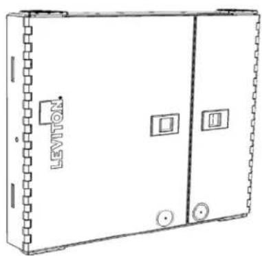
natural_image
Line drawing of a rectangular electrical cabinet with labeled components (no text or symbols beyond branding)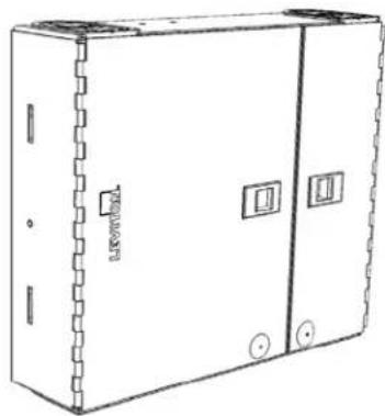
natural_image
Line drawing of an open electrical cabinet with mounting holes and a side panel (no text or symbols)5WMED-04C5WSML-02C
PK-A3188-10-00-0A
FIBER CONNECTOR SAFETY WARNINGS
SAFETY INFORMATION
• Always wear safety glasses.
- Isopropyl alcohol is flammable and may cause eye irritation. In case of contact with eyes, flush with water for at least 15 minutes. When using isopropyl alcohol, always assure proper levels of ventilation. In case of ingestion, consult a physician immediately.
- Never look directly into a laser light source, point source at a person's eyes, or point source at reflective surfaces.
- When working on a fiber link, always turn laser source off, or disconnect completely.
• Always dispose of fiber debris properly, preferably using sticky tabs.
- Do not place food or beverages in the vicinity of the work area.
• Thoroughly wash face and hands after terminating fiber.
- Carefully remove any fiber debris that may have been stuck to clothing, or left in work area, and dispose of properly.
TIPS
AND
RECOMMENDATIONS
• Using isopropyl alcohol, thoroughly clean exposed fiber and buffer ensuring both are free from dust, oil, and debris.
- Do not lay ferrule dust covers on a dirty or dusty surface.
• Always use proper tools and/or accessories to terminate fibers and clean connector tips.
QUICK START GUIDE
The following instructions will help you quickly install your Leviton Opt-X® Wallmount Enclosure for use in your equipment cabinet or rack. For detailed information on each step, go to the page number listed below.
| Safety | Instructions | Pg. | 2 | |||||
| Quick | Start | Guide | Pg. | 2 | ||||
| Equipment | Guide | Pg. | 3 | |||||
| Standard | Accessories | Pg. | 4 | |||||
| Optional | Accessories | Pg. | 4 | |||||
| Required | Hardware | and | Tools | Pg. | 4 | |||
| Configurations | P | g | . | 5 | ||||
| Adapter Plates | ||||||||
| Splicing | ||||||||
| SDX Cassette | ||||||||
| Mounting | Pg. 5 | |||||||
| Grommet | Preparation | and | Use | Pg. | 5 | |||
| Cable Installation Applications | ||||||||
| Adapter | Plates | Pg. | 7 | |||||
| SDX | Cassette | Pg. | 7 | |||||
| Splicing | Pg. | 8 | ||||||
| Grounding | armored | cabling | ||||||
| Installing the optional lock kit | Pg. 10 | |||||||
| Labeling | Pg. | 11 | ||||||
EQUIPMENT OVERVIEW - SMALL/MEDIUM, LARGE
Small/Medium Enclosure
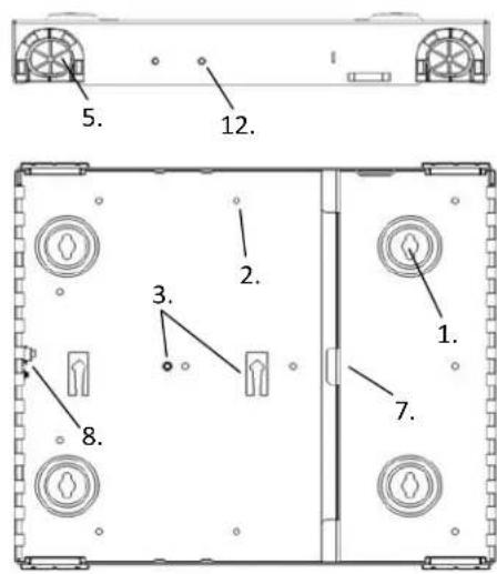
text_image
5. 12. 2. 3. 1. 7. 8.- Mounting Eyelets
- Wire management saddle mounting holes
- Splice tray mounting point
- Door latch
- Cable entrance grommet
- Cable lacing point
- SDX Bulkhead
- Grounding Stud
- Service Door
- Patch Door
- Optional lock knockout blank
- Optional Cable Clamp mounting point
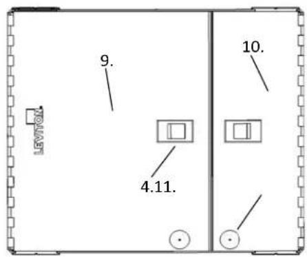
text_image
LEVTOX 9. 10. 4.11.Pour les traductions en français, allez à: Para las traducciones en español, visite: www.leviton.com
STANDARD ACCESSORIES
| Description | Image | Quantity Sm Kit | Quantity in Med Kit |
| Port Identification Label |  | 1 | 1 |
| Wire Management Saddles | 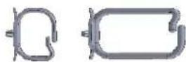 | 7 Small 7 Medium | |
| Velcro 5" 2 2 | — | ||
| Grommets 4 4 | 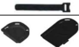 | ||
| #10 Wood Screw 4 4 | |||
| Grounding Lug 1 1 | 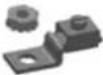 | ||
| Blank Adapter Plate 1 | 2 | ||
OPTIONAL ACCESORIES
| Lock and Key | 5L000-LOK | |||||
| Universal Clamp Kit (single) | 5RCMP-KIT | |||||
| Universal Clamp Kit (single) | 5RCMP-KT2 | |||||
| SDX to HDX adapter bracket HDXAD-ACC | ||||||
| Splice Trays | (See splice tray configurator) | |||||
| Splice Tray Mounting Hardware Kit SPLMT-HKT | ||||||
REQUIRED HARDWARE AND TOOLS
| Mounting screws/lag bolts, wall anchors, washers as appropriate | |||||
| Small | Magnetic | Torpedo | level | ||
| Powered | drill | or | screw | driver | |
| Scissors | or | safety | blade | utility | knife |
CONFIGURATIONS
There are four possible configurations using the small and medium enclosures.
1) Field or pre-terminated cabling used with SDX adapter plates
2) Pigtail splicing used with SDX adapter plates
3) Pigtail splicing used with Splice modules
4) Use with pre-terminated MTP cabling and SDX cassettes or SDX to HDX adapter brackets
See the Installation section for diagrams of each configuration.
MOUNTING INSTRUCTIONS
1) Determine the location to mount the enclosure. Use the following considerations in selecting a mounting location:
a) Appropriate mounting base per applicable codes and Authority Having Jurisdiction (AHJ)
b) Space around the enclosure to open the door and route patch cables.
c) Adequate space above or below the enclosure to maintain industry standard bend radius compliance of all cables entering the enclosure.
2) If using the large enclosure in the splice only configuration, install the splice tray hardware before mounting the enclosure.
3) Using a level, place the enclosure at the target mounting location and mark the four mounting hole positions.
4) Install the top two screws and verify the enclosure is level during final tightening of screws.
5) Install the bottom two screws.
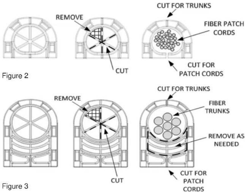
GROMMET PREPARATION AND USE
Cable Grommets are provided and designed for use at both trunk and patch cord entrance points to the enclosure.
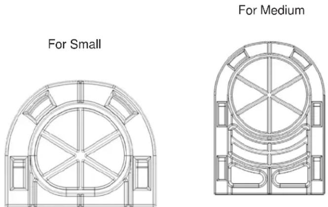
Figure 1
There are several options in configuring the grommets. When patching, it is recommended to cut a channel at the front of the grommet to easily install patch cords. When routing trunks it may be desired to cut a channel at the rear of the grommet to allow for grommet removal for adding additional trunk cables. Grommet pass through material can either be slit to limit dust and water egress or removed entirely. To configure a grommet, use the following cutting methods:
1) Determine required opening in cable entrance grommet
2) Determine whether slitting or removing material will be performed
3) Using a sharp-edged tool, cut the appropriate opening in using the scored marking lines as shown in figures 2 and
3:
4) Optional – cut a channel through the outer wall of the grommet for either trunk or patch cord routing.
PK-A3188-10-00-0A
text_image
CUT FOR TRUNKS FIBER PATCH CORDS CUT FOR PATCH CORDS CUT FOR TRUNKS FIBER TRUNKS REMOVE AS NEEDED CUT FOR PATCH CORDS Figure 2 Figure 3Estimated Fill Ratios
| Cable Description (based on 50% fill) | Diameter in inches | Diameter in MM | Qty per Small Grommet | Qty per Medium Grommet |
| Micro Data Center 12s Plenum 0.16 4.06 | 15 26 | |||
| Micro Data Center 24s Plenum 0.18 4.57 | 12 20 | |||
| Micro Data Center 48s Plenum 0.231 5.87 | 7 12 | |||
| Micro Data Center 72s Plenum 0.275 6.99 | 5 9 | |||
| Micro Data Center 144s Plenum 0.36 9.14 | 3 5 | |||
| Trunk 12s Distribution/Loose Tube 0.18 | 4.57 12 20 | |||
| Trunk 24s Distribution/Loose Tube 0.38 | 9.65 3 5 | |||
| Trunk 48s Distribution/Loose Tube 0.38 | 9.65 3 5 | |||
| Trunk 72s Distribution/Loose Tube 0.44 | 11.18 2 3 | |||
| Trunk 144s Distribution/Loose Tube 0.69 | 17.53 1 1 | |||
| Trunk 12s Armored - MDP 0.495 12.57 2 3 | ||||
| Trunk 24s Armored - MDP 0.495 12.57 2 3 | ||||
| Trunk 48s Armored - MDP 0.584 14.83 1 2 | ||||
| Trunk 72s Armored - MDP 0.594 15.09 1 2 | ||||
| Trunk 144s Armored - MDP 0.708 17.98 1 1 | ||||
| Trunk 12s Armored - All types 0.55 13.97 1 2 | ||||
| Trunk 24s Armored - All types 0.95 24.13 0 1 | ||||
| Trunk 48s Armored - All types 1.05 26.67 0 1 | ||||
| Trunk 72s Armored - All types 1.23 31.24 0 0 | ||||
| Trunk 144s Armored - All types 1.73 43.94 0 0 | ||||
| Generic UTP Copper Cat5e | 0.185 4.70 | 11 19 | ||
| Generic UTP Copper Cat6 | 0.23 5.84 | 7 12 | ||
| Generic UTP Copper Cat6A | 0.33 8.38 | 4 6 |
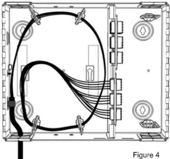
CABLE INSTALLATION
1) Feed incoming cable(s) through the grommet opening.
2) Optional – Install Universal Trunk Clamp kit and secure cable to clamp.
3) Remove required outer cable jacket leaving jacket at the closest lance point.
4) Secure the cable to the lance point with Velcro or nylon tie wraps as appropriate.
5) If applicable, secure aramid yarn to lance point.
6) When using Armored cable, secure the ground wire from the armored cable to the provided grounding lug or ground by other code compliant methods to the provided grounding stud.
7) Using the cable management saddles, route the breakout fiber legs to the patching or termination point as shown in the configuration drawings below: (Figures 4 to 11)
ROUTING FOR FIELD AND PRE-TERMINATED TERMINATION – (SMALL/MEDIUM ENCLOSURES)
natural_image
Technical line drawing of an electronic device chassis with internal wiring and labeled components (no readable text or symbols)ROUTING FOR FIELD TERMINATED CABLING - SPLICE MODULES
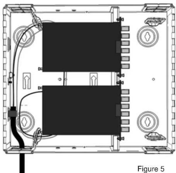
natural_image
Top-down schematic of an electronic device showing two rectangular modules with wiring and connectors, labeled as Figure 5 (no text or symbols on the diagram itself)ROUTING FOR PRE-TERMINATED CABLING - CASSETTES
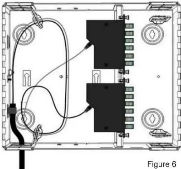
natural_image
Technical diagram of an electronic device showing internal components and wiring (no text or labels)ROUTING FOR FIELD TERMINATED CABLING - FAN OUT

natural_image
Technical line drawing of an electronic device chassis with visible wiring and ports (no text or symbols)ROUTING FOR SPLICE TERMINATION
When performing splice terminations, it is recommended to pre-route and mark trunk and pigtail cabling prior to performing any trimming, termination or routing. Splice work can then be performed outside of the enclosure at the termination equipment. When routing terminated assemblies, route in the trunk cabling (solid line in Figure 8) first, followed by the pigtail assemblies (dotted line in Figure 8). To maintain future accessibility, keep each set of cabling (trunk and pigtail respectively) routed separately through the Wire Management saddles.
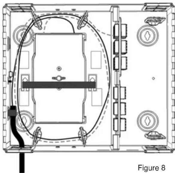
natural_image
Top-down schematic of a device layout with labeled components and wiring (no text or symbols beyond label)The Splice Tray Mounting Hardware Kit (SPLMT-HKT) is required for securing Splice trays to all Opt-X wall mount enclosures. Upon completion of splicing and routing, secure the splice trays to the enclosure base using the arrow lance points, appropriate threaded stud and wing nut from the Splice hardware kit.
SECURING THE SPLICE TRAYS
Securing the splice trays requires two components:
- Splice Tray Mounting Kit including appropriate threaded stud and wing nut
-
Velcro strip (bulk Velcro or Velcro supplied in the Splice Tray Mounting Kit)
-
Prior to mounting the enclosure, install appropriate #10-32 threaded bolt from the rear of the enclosure base and secure trays with wing nut.
-
Insert Velcro strip under the first arrow lance point with the hook side facing up (Figure 9).
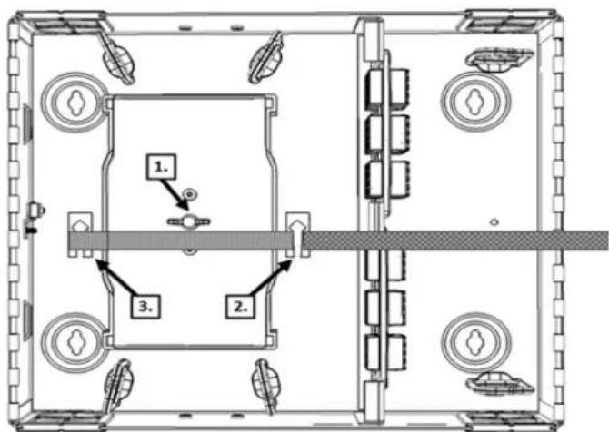
text_image
1. 2. 3.Figure 9
- Place the Velcro under and around the second lance point
- Fold the end over the splice tray(s). (Figure 10).
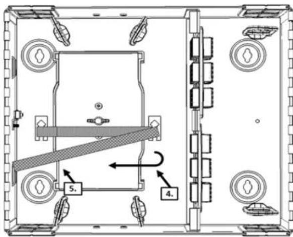
text_image
Technical diagram of a mechanical assembly with labeled components and directional arrows indicating movement or force.Figure 10
- Create a snug mating of the Velcro to the trays. (Figure 11).
- Trim excess Velcro as necessary.
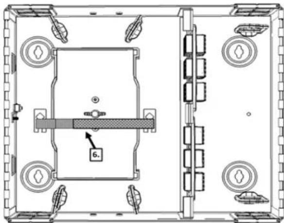
natural_image
Technical line drawing of a mechanical assembly with no visible text or symbolsFigure 11
OPTIONAL LOCK KIT
A lock can be installed on the service door, patch door or both doors of each enclosure as required. If using the optional Lock kit #5L000-LOK
Small and Medium
- Remove the plastic lock blank
- Remove the CAM from the lock set
- Insert the lock set into the Enclosure door
- Re-install the lock CAM
LABELING
A Port Identification Label is provided with each Wall Mount Enclosure. The label(s) should be affixed to the inside of the patch bay door. Labeling within the slot position cells can be achieved with printed labels or via excel based spreadsheets available via download at www.leviton.com.
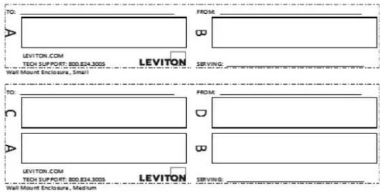
text_image
TO: A LEVIYTON.COM TECH SUPPORT: 800.824.300S FROM: B LEVITON SERVING: Wall Mount Enclosure, Small TO: C A FROM: D B LEVITON.COM TECH SUPPORT: 800.824.300S LEVITON SERVING: Wall Mount Enclosure, MediumAffix labels as shown in the following Labeling Configuration matrix
| Label Printing Organization by Fiber Adapter Type Vertical Orientation | ||||||||
| Adapter | Duplex SC (3 pack) | Duplex SC (6 pack) | Duplex LC (6 pack) | Quad LC (6 pack) | ST/FC (6 pack) | ST/FC (8 pack) | ||
| No. of Ports | 6 | 12 | 12 | 24 | 6 | 8 | ||
| Number Scheme | ||||||||
| 1 | 1-2 | 3-4 | 1-2 | 1-2 3-4 | 5-6 7-8 | 1 | 1 | |
| 2 | 3-4 | 2 | 2 | |||||
| 3 | 5-6 | 7-8 | 5-6 | 9-10 11-12 | 13-14 15-16 | 3 | 3 | |
| 4 | 7-8 | 4 | 4 | |||||
| 5 | 9-10 | 11-12 | 9-10 | 17-18 19-20 | 21-22 23-24 | 5 | 5 | |
| 6 | 11-12 | 6 | 6 | |||||
NOTE: Ensure that the label surface area is clean of dirt, oil, and debris. Recommend use of isopropyl alcohol or a simple soap and water solution when wiping down surface area.
UNIVERSAL LABELING DEVICES
Vertical orientation
- Use 3/8" or 3/4" label tape, depending on adapter plate
• Total label length = 2 3/4"
• Panel section is 3/4" W x 2 3/4" H
Horizontal orientation
- Use 3/8" or 3/4" label tape, depending on adapter plate
• Total label length = 4" - Panel section is 3/4" H x 4" L