
STRAN1000 - Home Theater System SONY - Free user manual and instructions
Find the device manual for free STRAN1000 SONY in PDF.

User questions about STRAN1000 SONY
0 question about this device. Answer the ones you know or ask your own.
Ask a new question about this device
Download the instructions for your Home Theater System in PDF format for free! Find your manual STRAN1000 - SONY and take your electronic device back in hand. On this page are published all the documents necessary for the use of your device. STRAN1000 by SONY.
USER MANUAL STRAN1000 SONY
User Manual of Product 1:
Sony STR-AN1000 7.2 CH Surround Sound Home Theater 8K A/V Receiver: Dolby Atmos, DTS:X, Digital Cinema Auto Calibration IX, Bluetooth, WiFi, Google Chromecast, Spotify connect, Apple AirPlay, HDMI 2.1
User Manual of Product 2:
Sony SA-RS5 Wireless Rear Speakers with Built-in Battery for HT-A7000/A5000/A3000 and STR-AN1000
SONY®
Multi Channel
AV Receiver
Récepteur
AV Multicanal
Operating Instructions
Mode d'emploi
Record the serial number in the space provided below. Refer to them whenever you call upon your Sony dealer.
Model No. STR-AN1000
Serial No. ____
The model and serial numbers are located on the following:
- The rear of the unit
Do not install the product in a confined space, such as a bookcase or built-in cabinet.
To reduce the risk of fire, do not cover the ventilation opening of the unit with newspapers, tablecloths, curtains, etc. Do not expose the unit to naked flame sources (for example, lighted candles).
To reduce the risk of fire or electric shock, do not expose this product to dripping or splashing, and do not place objects filled with liquids, such as vases, on the product.
The unit is not disconnected from the AC power source (mains) as long as it is connected to the wall outlet, even if the unit itself has been turned off.
As the power cord is used to disconnect the unit from the mains, connect the unit to an easily accessible AC outlet. Should you notice an abnormality in the unit, disconnect the power cord from the AC outlet immediately.
For Remote Commander
CAUTION
Risk of explosion if battery is replaced by an incorrect type.
Dispose of used batteries according to the instructions.
Do not expose the batteries (battery pack or batteries installed) to excessive heat, such as sunshine, fire or the like for a long time.

CAUTION
Hot surface
Do not touch
For customers in the U.S.A.
NOTE:
This unit has been tested and found to comply with the limits for a Class B digital device, pursuant to Part 15 of the FCC Rules. These limits are designed to provide reasonable protection against harmful interference in a residential installation. This unit generates, uses, and can radiate radio frequency energy and, if not installed and used in accordance with the instructions, may cause harmful interference to radio communications.
However, there is no guarantee that interference will not occur in a particular installation. If this unit does cause harmful interference to radio or television reception, which can be determined by turning the unit off and on, the user is encouraged to try to correct the interference by one or more of the following measures:
- Reorient or relocate the receiving antenna.
- Increase the separation between the unit and receiver.
- Connect the unit into an outlet on a circuit different from that to which the receiver is connected.
- Consult the dealer or an experienced radio/TV technician for help.
Properly shielded and grounded cables and connectors must be used for connection to host computers and/or peripherals in order to meet FCC emission limits.
If you have any questions about this product:
Visit: https://www.sony.com/electronics/support
Contact: Sony Customer Information Service Center at 1-800-222-7669
Write: Sony Customer Information Service Center 12451 Gateway Blvd., Fort Myers, FL 33913
Supplier's Declaration of Conformity Trade Name: SONY
Model: STR-AN1000
Responsible Party: Sony Electronics Inc.
Address: 16535 Via Esprillo, San Diego, CA 92127 U.S.A.
Telephone Number: 858-942-2230
This device complies with Part 15 of the FCC Rules. Operation is subject to the following two conditions:
(1) this device may not cause harmful interference, and
(2) this device must accept any interference received, including interference that may cause undesired operation.
You are cautioned that any changes or modifications not expressly approved in this manual could void your authority to operate this unit.
This unit must not be co-located or operated in conjunction with any other antenna or transmitter.
This unit complies with FCC radiation exposure limits set forth for an uncontrolled environment and meets the FCC radio frequency (RF) Exposure Guidelines. This unit should be installed and operated keeping the radiator at least 20 cm or more away from person's body.
Compliance with FCC requirement 15.407(c) Data transmission is always initiated by software, which is passed down through the MAC, through the digital and analog baseband, and finally to the RF chip. Several special packets are initiated by the MAC. These are the only ways the digital baseband portion will turn on the RF transmitter, which it then turns off at the end of the packet. Therefore, the transmitter will be on only while one of the aforementioned packets is being transmitted. In other words, this unit shall automatically discontinue transmission in case of either absence of information to transmit or operational failure.
Frequency Tolerance: ±20 ppm
For customers in Canada
This unit contains licence-exempt transmitter(s)/receiver(s) that comply with Innovation, Science and Economic Development Canada's licence-exempt RSS(s). Operation is subject to the following two conditions:
(1) This unit may not cause interference; and
(2) This unit must accept any interference, including interference that may cause undesired operation of the unit.
This unit complies with ISED radiation exposure limits set forth for an uncontrolled environment and meets RSS-102 of the ISED radio frequency (RF) Exposure rules. This unit should be installed and operated keeping the radiator at least 20 cm or more away from person's body.
5 150 MHz – 5 350 MHz band is restricted to indoor operations only.
Data transmission is always initiated by software, which is passed down through the MAC, through the digital and analog baseband, and finally to the RF chip. Several special packets are initiated by the MAC. These are the only ways the digital baseband portion will turn on the RF transmitter, which it then turns off at the end of the packet. Therefore, the transmitter will be on only while one of the aforementioned packets is being transmitted. In other words, this unit shall automatically discontinue transmission in case of either absence of information to transmit or operational failure.
About recommended cables
Properly shielded and grounded cables and connectors must be used for connection to host computers and/or peripherals.
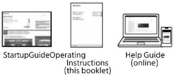
Manuals provided for this product
The following manuals are provided for this product.
The information included in each manual is as shown below:
Preparation
Installation
Connections
Initial Setup
Basic operations
Listening/Watching
Advanced operations
Listening/Watching
Advanced operations
BLUETOOTH features
Network features
Multi-zone features
Sound effect features
Other features
Adjusting settings
Troubleshooting
Precautions / Specifications
To read the Help Guide, go to the following website:
https://rd1.sony.net/help/ha/strtaan10/h_zz/

About These Operating Instructions
• These Operating Instructions mainly describe the procedures for using the remote control. You can also use the controls on the receiver if they have the same or similar names as those on the remote control.
- Some illustrations are presented as conceptual drawings, and may be different from the actual products.
- The items displayed on the TV screen may vary depending on the area.
- The text enclosed in bracket ([--]) appears on the TV screen, and the text enclosed in double quotation mark (“--”) appears on the display panel.
Table of Contents
Manuals provided for this product ....4
About These Operating Instructions ....5
Supplied Accessories 6
Parts and Controls....7
Preparation
Installing Speakers....15
Connecting Speakers ....17
Connecting to Sony wireless rear speaker/subwoofer....26
Connecting a TV 28
Connecting Audio-Visual Devices....33
Connecting the Antenna (aerial)....39
Connecting to a Network ....39
Preparing the Receiver....41
Setting up the Receiver using the Easy Setup....42
Listening/Watching
Playing AV devices/Listening to FM radio ...44
Using the Multi-Zone Features ....45
Enjoying Sound Effects ....47
Listening with BLUETOOTH headphones/speakers....51
What you can do with network features.....52
Additional Information
Saving power ....53
Reverting to the factory default settings.....53
Updating the Software....54
Troubleshooting....55
Precautions....60
Specifications....64
Supplied Accessories
- Remote control (1)
• R03 (size AAA) batteries (2)
• FM wire antenna (aerial) (1)

- Calibration microphone (1)

natural_image
Line drawing of a cable with a clip and connector (no text or symbols)- Calibration mic stand – Mic stand top (1)
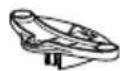
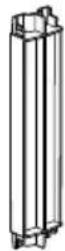
- Mic stand pillar (1)
- Mic stand bottom (1)

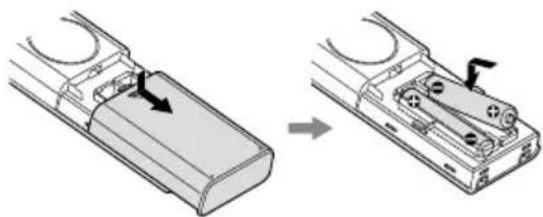
Inserting batteries into the remote control
Insert two R03 (size AAA) batteries (supplied) in the remote control. Make sure that the + and - ends are in the correct position when installing batteries.
natural_image
Diagram showing a device being processed from a left-side component to an external casing (no text or symbols present)Note
- Do not leave the remote control in an extremely hot or humid place.
- Do not use a new battery with old ones.
- Do not mix manganese batteries and other kinds of batteries.
- Do not expose the remote control sensor to direct sunlight or lights. Doing so may cause a malfunction.
- If you do not intend to use the remote control for an extended period of time, remove the batteries to avoid possible damage from battery leakage and corrosion.
- When the receiver no longer responds to the remote control, replace both of the batteries with new ones.
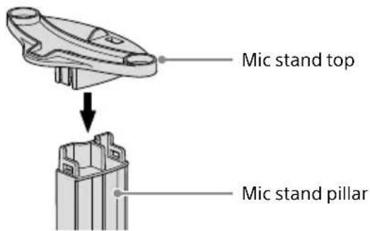
Assembling the calibration mic stand
1 Insert the mic stand pillar all the way into the mic stand bottom.
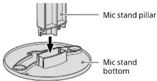
2 Insert the mic stand top all the way into the mic stand pillar.
Parts and Controls
Receiver
Front panel
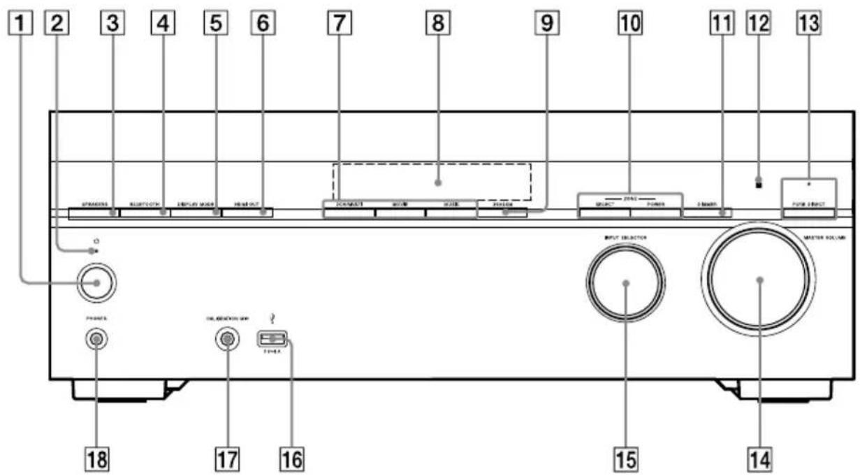
1 ⏻ (power) (page 42)
2 Power indicator (page 8)
3 SPEAKERS (page 43)
4 BLUETOOTH
Switches the receiver to the BLUETOOTH®
function by pressing the button when
[Bluetooth Mode] is set to [Receiver].
When the button is pressed and held for more than 2 seconds, the receiver enters the pairing mode.
5 DISPLAY MODE
Switches information on the display panel.
6 HDMI OUT
7 2CH/MULTI, MOVIE, MUSIC (page 47)
8 Display panel (page 9)
9 360SSM
Activates or deactivates the
360 Spatial Sound Mapping function (page 47).
10 ZONE SELECT, ZONE POWER (page 45)
11 DIMMER
Adjusts the brightness of the display panel.
12 Remote control sensor
Receives signals from remote control.
13 PURE DIRECT
The indicator above the button lights up when the Pure Direct function is activated.
14 MASTER VOLUME (page 44)
15 INPUT SELECTOR (page 44)
16 ♂ (USB) port
Connect a USB device here.
17 CALIBRATION MIC jack (page 41)
18 PHONES jack
Connect headphones here.
Power indicator
- Green: The receiver is turned on. - Amber: The receiver is in standby mode, and you have set one of the following:
- [Control for HDMI] or [Network/Bluetooth Standby] is set to [On].
- [Standby Through] is set to [On] or [Auto].
- [Power] is set to [On] for [Zone2] or [Zone3].
- The indicator goes off: The receiver is in standby mode and all of the following settings are set to [Off]:
- [Control for HDMI]
- [Standby Through]
- [Network/Bluetooth Standby]
- [Power] for [Zone2] and [Zone3]
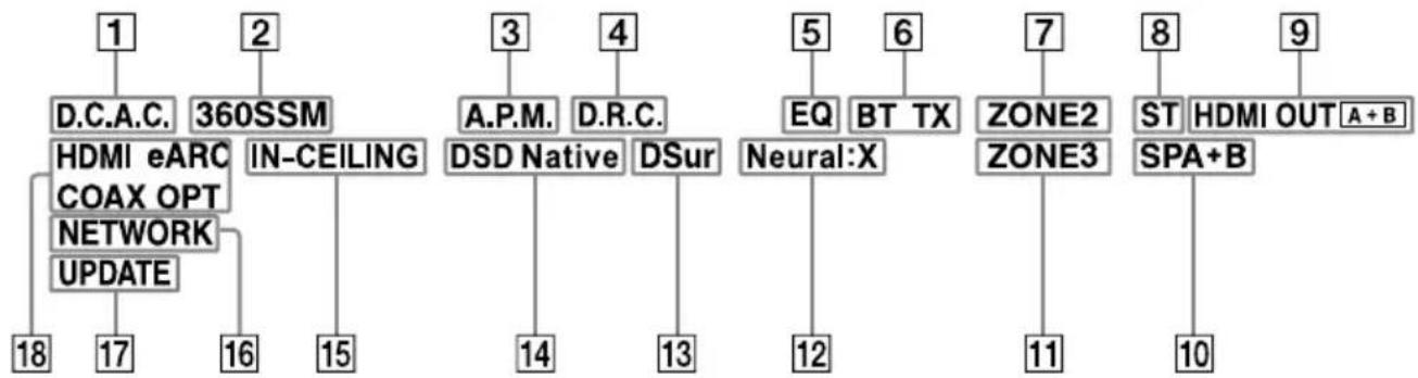
Indicators on the display panel
flowchart
graph TD
    A["1"] --> B["D.C.A.C."]
    C["2"] --> D["360SSM"]
    B --> E["HDMI eARC COAX OPT NETWORK UPDATE"]
    D --> F["IN-CEILING"]
    F --> G["18"]
    D --> H["3"]
    H --> I["A.P.M."]
    H --> J["D.R.C."]
    I --> K["DSD Native"]
    J --> L["DSur"]
    K --> M["14"]
    L --> N["13"]
    M --> O["5"]
    N --> P["EQ"]
    N --> Q["BT TX"]
    O --> R["Neural:X"]
    P --> S["7"]
    Q --> T["ZONE2"]
    Q --> U["ZONE3"]
    S --> V["11"]
    T --> W["ST"]
    T --> X["HDMI OUT A+B"]
    W --> Y["SPA+B"]
    X --> Z["10"]
1 D.C.A.C. Lights up when the measurement results of the Auto Calibration (D.C.A.C. IX) function are applied.
2 360SSM
Lights up when the 360 Spatial Sound Mapping function is activated (page 47).
3 A.P.M. Lights up when the A.P.M. (Automatic Phase Matching) function is activated. You can only set the A.P.M. function in the D.C.A.C. function.
4 D.R.C.
Lights up when dynamic range compression is activated.
5 EQ
Lights up when the equalizer is activated.
6 BLUETOOTH indicator
"BT" lights up when a BLUETOOTH device is connected. Flashes while connecting.
"BT TX" lights up when [Bluetooth Mode] is set to [Transmitter].
7 ZONE2
Lights up when the power for Zone 2 is on.
8 ST
Lights up when the receiver tunes to a FM stereo broadcast.
9 HDMI OUT A + B
Indicates the HDMI OUT jacks that currently output the audio/video signals.
10 Speaker system indicator (page 43)
11 ZONE3
Lights up when the power for Zone 3 is on.
12 Neural:X
Lights up when DTS Neural:X decoding is activated.
13 DSur Lights up when Dolby Surround decoding is activated.
Note
These indicators may not light up depending on the speaker pattern setting.
14 DSD Native
Lights up when the DSD Native function is activated.
15 IN-CEILING
Lights up when the In-Ceiling Speaker Mode is activated.
16 NETWORK
Lights up when the receiver is connected to wireless LAN or wired LAN.
17 UPDATE
Lights up when new software is available for download.
18 Input indicator
Lights up to indicate the current input signals to the receiver.
HDMI
Digital signals are input through the selected HDMI IN jack.
eARC (ARC)
"eARC" lights up when eARC signals are input through the HDMI OUT A (TV) jack, and "ARC" for ARC signals.
COAX
Digital signals are input through the COAXIAL IN SA-CD/CD jack.
OPT
Digital signals are input through the OPTICAL IN TV jack.
Rear panel
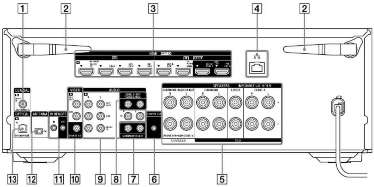
1 COAXIAL IN SA-CD/CD jack
2 Wireless LAN antenna
3 HDMI IN/OUT jacks
4 LAN port
5 SPEAKERS terminals
6 S-CENTER OUT jack (page 30)
7 SUBWOOFER OUT jacks
8 ZONE 3 OUT jacks
9 AUDIO IN jacks
10 VIDEO IN/MONITOR OUT jacks
11 IR REMOTE IN/OUT jacks
- You can control the receiver from a distance by connecting an IR repeater (not supplied) to the IR REMOTE IN jack.
- You can start or stop playback of devices such as a CD player connected to the receiver by connecting an IR blaster (not supplied) to the IR REMOTE OUT jack.
12 FM ANTENNA terminal
13 OPTICAL IN TV jack
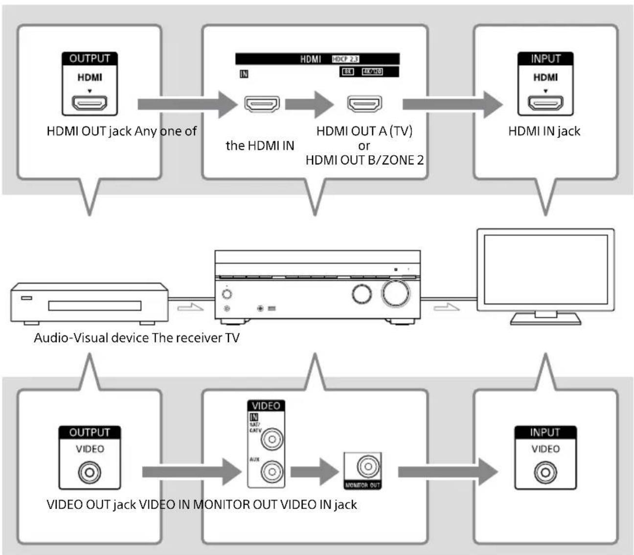
About input/output of video signals
The digital video signals input to the HDMI IN jacks of this receiver are output from
HDMI OUT A (TV) or HDMI OUT B/ZONE 2 jacks only. The analog video signals input from VIDEO IN jacks are output from the MONITOR OUT jack only.
Use the following illustration as reference when you connect the receiver, AV device, and TV.
flowchart
graph TD
    A["OUTPUT HDMI"] --> B["HDMI OUT jack Any one of"]
    B --> C["the HDMI IN"]
    C --> D["HDMI OUT A (TV) or HDMI OUT B/ZONE 2"]
    D --> E["INPUT HDMI"]
    E --> F["HDMI IN jack"]
    G["Audio-Visual device The receiver TV"] --> H["CPU"]
    H --> I["Monitor"]
    I --> J["OUTPUT VIDEO"]
    J --> K["VIDEO OUT jack VIDEO IN MONITOR OUT VIDEO IN jack"]
    K --> L["INPUT VIDEO"]
Note
When you connect the TV to the MONITOR OUT jack, the home menu of this receiver is not displayed on the TV screen. To operate this receiver using the menu on the TV screen, connect the TV to the HDMI OUT A (TV) or HDMI OUT B/ZONE 2 jacks.
Remote control
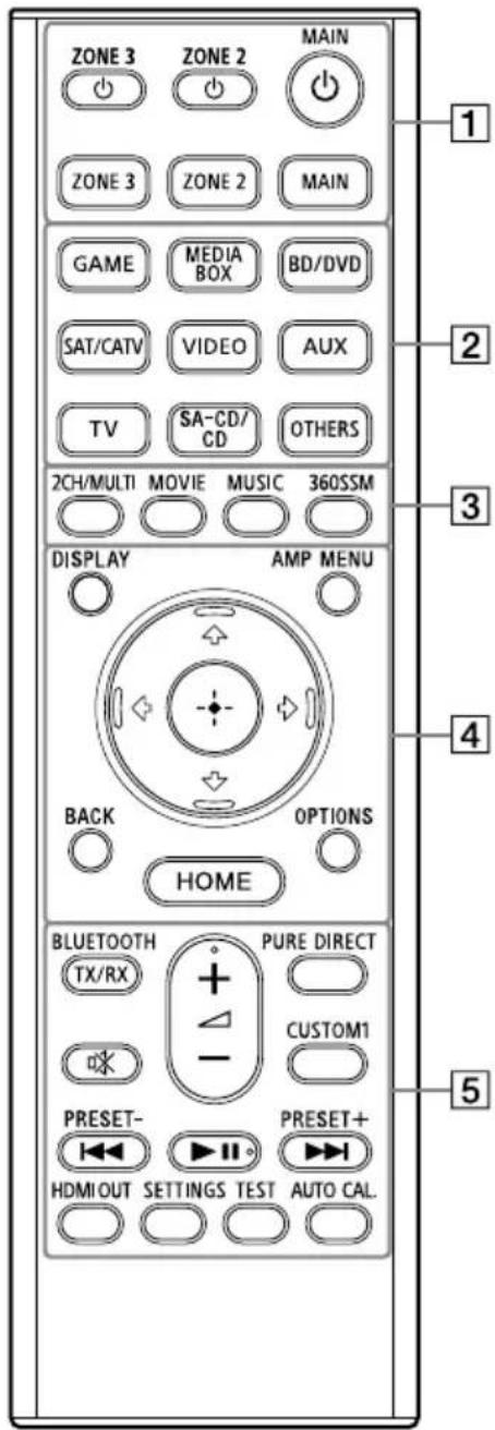
1 ⏻ (power) buttons (MAIN, ZONE 2, ZONE 3)
Turns the receiver in the main zone, Zone 2 or Zone 3 on or sets it to standby mode.
MAIN, ZONE 2, ZONE 3
Selects the location to be controlled.
For details, see "Buttons that can be operated for each zone" (page 14).
2 Input buttons
GAME, MEDIA BOX, BD/DVD, SAT/CATV, VIDEO, AUX, TV, SA-CD/CD, OTHERS
Selects the input connected to the device you want to play. When you press any of the input buttons, the receiver turns on.
- Press OTHERS button repeatedly to select playback source other than above.
3 2CH/MULTI, MOVIE ^1) , MUSIC ^1)
Selects a sound field.
360SSM
Activates or deactivates the
360 Spatial Sound Mapping function (page 47).
4 DISPLAY
Displays information on the TV screen.
AMP MENU
Displays the menu on the display panel to operate the receiver.
BACK
Returns to the previous menu or exits a menu or on-screen guide that is displayed on the TV screen.
OPTIONS
Displays the options menus.
(The menu is not displayed for the TV input.)
(enter), / // ↓ ← →
Press ↑, ↓, ◀to select the menu items. Then, press ⊙ to enter the selection.
HOME
Displays the home menu on the TV screen.
5 BLUETOOTH TX/RX
Switches the [Bluetooth Mode] to [Transmitter] or [Receiver].
In [Transmitter] mode, the receiver sends audio to BLUETOOTH headphones/speakers.
In [Receiver] mode, the receiver receives and outputs audio from the player.
☐X (muting)
Turns off the sound temporarily. Press the button again to restore the sound.
PURE DIRECT
Activates or deactivates the Pure Direct function.
CUSTOM1
Saves and recalls various settings for the receiver. Press to select the custom preset setting. Press and hold to save the current settings to a preset.
(volume ^2 )A-
Adjusts the volume level of all speakers at the same time.
I◀◀/▶▶▶ (previous/next),
▶II (play/pause) ^2)
Skip, play, pause operation.
PRESET +/-
Selects preset stations or channels. Press and hold to scan stations automatically.
HDMI OUT
Switches the output for two TVs connected to the HDMI OUT A (TV) and HDMI OUT B/ZONE 2 jacks.
When [HDMI OUT B Mode] is set to [Main] in the [HDMI Settings] menu, output is toggled between "HDMI A", "HDMI B", "HDMI A+B" and "HDMI OFF" each time the button is pressed. Select "HDMI OFF" to turn off the output for the HDMI OUT A (TV) and HDMI OUT B/ZONE 2 jacks. When [HDMI OUT B Mode] is set to [Zone2], output is toggled between "HDMI A" and "HDMI OFF" each time the button is pressed.
SETTINGS
Displays the [Setup] menu on the TV screen.
TEST
Displays the [Test Tone] selection screen on the TV screen.
AUTO CAL.
Press to perform Auto Calibration.
^1) The sound fields for movie and music may not work, depending on the input or the speaker pattern you select, or with audio formats.
2) The ▶II and △+ buttons have tactile dots. Use the tactile dots as reference when operating the receiver.
Note
- The above explanation is intended to serve as examples.
- Depending on the model of your connected device, some functions explained in this section may not work with the supplied remote control.
Buttons that can be operated for each zone
| Buttons Operation target zone of the remote control | |||
| (power) buttonZONE 3, ZONE 2, MAIN | ● ● ● | ||
| ZONE 3, ZONE 2, MAIN | ● ● ● | ||
| Input selection buttonsGAME, MEDIA BOX, BD/DVD, SAT/CATV,VIDEO, AUX, TV, SA-CA/CD, OTHERS | ● ● ● | ||
| Sound field buttons2CH/MULTI, MOVIE, MUSIC | ● | — — | |
| 360SSM | ● | — — | |
| DISPLAY | ● | — | — |
| AMP MENU | ● | — — | |
| +/←→, ←enter) | ● ●* ●* | ||
| BACK | ● ●* ●* | ||
| HOME | ● ●* ●* | ||
| OPTIONS | ● | — | — |
| BLUETOOTH TX/RX | ● | — — | |
| ※ (muting) ● | — | ● | |
| △ (volume) +/- ● | — | ● | |
| PURE DIRECT | ● | — — | |
| CUSTOM1 | ● | — — | |
| ▶II play/pause ● | — — | ||
| ◀◀ PRESET -,▶◀ PRESET + | ● | — | ● |
| HDMI OUT | ● | — — | |
| SETTINGS | ● | — — | |
| TEST | ● | — — | |
| AUTO CAL. | ● | — — | |
● : Operable
—: Not operable
* You can operate the menu on the TV screen in the main zone.
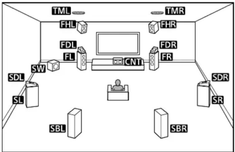
Installing Speakers
You can connect up to 7 speakers and 2 subwoofers to this AV receiver. Place the speakers and subwoofers according to the speaker system of your preference.
Speaker installation example
flowchart
graph TD
    TML --> FHL
    TML --> FDR
    TML --> FHR
    FHL --> FDL
    FHL --> FL
    FDR --> FR
    FDR --> CNT
    CNT --> SW
    SW --> SDL
    SW --> SL
    CNT --> SBR
    CNT --> SBL
    CNT --> SBR
    FHL --> FDR
    FDR --> FR
    FHL --> FHR
    FDL --> FHR
    FDR --> FHR
    FHL --> SDL
    FDR --> SBR
    FHL --> SBR
    FDR --> SBR
    FHL --> SDL
    FDR --> SBR
    FHL --> SDL
    FDR --> SBR
    FHL --> SDL
    FDR --> SBR
    FHL --> SDL
    FDR --> SBR
    FHL --> SDL
    FDR --> SBR
    FHL --> SDL
    FDR --> SBR
    FHL --> SDL
    FDR --> SBR
    FHL --> SDL
    FDR --> SBR
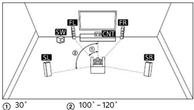
Tip
As the subwoofer (SW) does not emit highly directional signals, you can place it wherever you want.
| Abbreviations used in illustrations | Speaker name Functions | |
| FL Front left speaker | Produces sounds from front left/right channels. | |
| FR Front right speaker | ||
| CNT Center speaker | Produces vocal sounds from center channel. | |
| SL Surround left speaker | Produces sounds from surround left/right channels. | |
| SR Surround right speaker | ||
| SBL | Surround back left speaker | Produces sounds from surround back left/right channels. |
| SBR | Surround back right speaker | |
| SW Subwoofer | Produces LFE (low frequency effect) channel sounds and reinforces bass parts of other channels. | |
| TML Top middle left speaker | Produces sounds from top middle left/right channels. | |
| TMR Top middle right speaker | ||
| FDL | Front Dolby Atmos enabled left speaker | Produces sounds from the top middle left/right channels and reflects these sounds off the ceiling. Enables playing back sounds of Dolby Atmos 3D movies without the need to install ceiling speakers. |
| FDR | Front Dolby Atmos enabled right speaker | |
| SDL | Surround Dolby Atmos enabled left speaker | Produces sounds from the top middle left/right channels and reflects these sounds off the ceiling. Enables playing back sounds of Dolby Atmos 3D movies without the need to install ceiling speakers. |
| SDR | Surround Dolby Atmos enabled right speaker | |
| FHL Front high left speaker | Produces vertical sound effects from front height left/right channels. | |
| FHR Front high right speaker | ||
Connecting Speakers
Note
- Connect speakers with a nominal impedance of 6 ohms to 16 ohms.
- Before connecting cables, be sure to disconnect the AC power cord (mains lead).
- Before connecting the AC power cord (mains lead), make sure that metallic wires of the speaker cables are not touching each other between the SPEAKERS terminals.
- When you connect a subwoofer with an auto standby function, turn off the function when watching movies. If the auto standby function is set to on, it turns to standby mode automatically based on the level of the input signal to the subwoofer, and the sound may not be output.
- If you have two subwoofers, you can connect them to both SUBWOOFER OUT jacks.
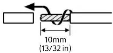
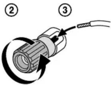
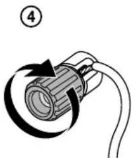
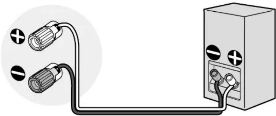
How to connect speaker cables
Be sure to connect the speaker cables correctly to the terminals of the speaker and this receiver. Also, be sure to tightly twist the speaker wire strands and insert them securely into the speaker terminals.
①
natural_image
Diagram of a cable with a coiled connector and directional arrow indicating rotation (no text or symbols)Note
- Be sure not remove too much of the speaker cable sleeves, so as to prevent the wires of the speaker cables from touching each other.
- Connect speaker cables properly with the polarities (+/-) matched between the receiver and the speakers.
natural_image
Pure electrical circuit lines without any symbols- Improper connection may result in fatal damage to the receiver.
Speaker configuration and speaker pattern settings
This receiver allows you to connect up to a 7.1-channel system.
The table below shows examples of speaker configurations and speaker pattern settings. For details on connections, see page 19 to 24.
| Speaker configuration in each zone [ | Surround Back Speaker Assign]* | [SpeakerPattern] setting | For connection, see page | |
| Main zone Zone 3 | ||||
| 5.1-channel Not used — [5.1] 19 | ||||
| 7.1-channel using surround back speakers | Not used — [7.1] 20 | |||
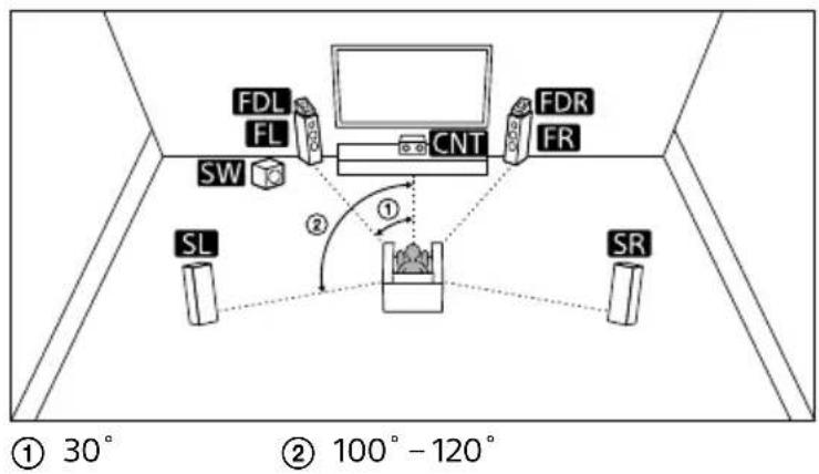
| 5.1.2-channel using top middle speakers | Not used — [5.1.2 (TM)] 21 | |||
| 5.1.2-channel using Dolby Atmos enabled speakers | Not used — [5.1.2 (FD)] 22 | |||
| 5.1-channel with Zone 3 speakers | 2-channel [Zone3] [5.1] 23 | |||
| 5.1-channel with Bi-Amplifier connection | Not used [BI-AMP] [5.1] 24 | |||
* You can only set [Surround Back Speaker Assign] if the speaker pattern is set to a setting that does not have surround back and height speakers.
Tip
- This receiver allows you to connect Sony wireless rear speakers and a Sony subwoofer (page 26).
- When your Sony TV has the S-CENTER SPEAKER IN jack, you can output the center part of the receiver sound from the TV speaker (page 30).
- By setting [SpeakerRelocation/PhantomSurroundBack] to [Type A] or [Type B] in the [Audio Settings] menu, you can enjoy a surround effect equivalent to up to 7.1.2 channels in terms of hearing. When you set [SpeakerRelocation/PhantomSurroundBack], perform Auto Calibration in advance (page 43).
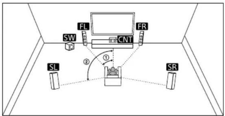
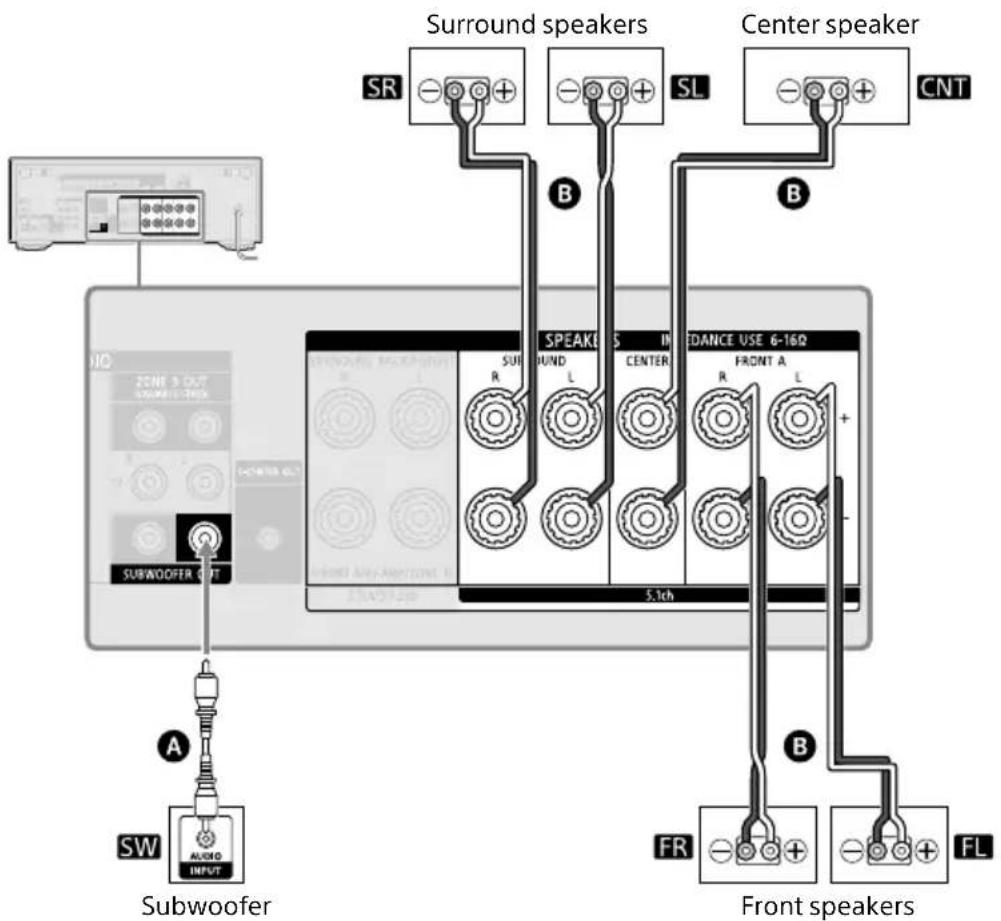
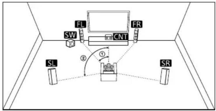
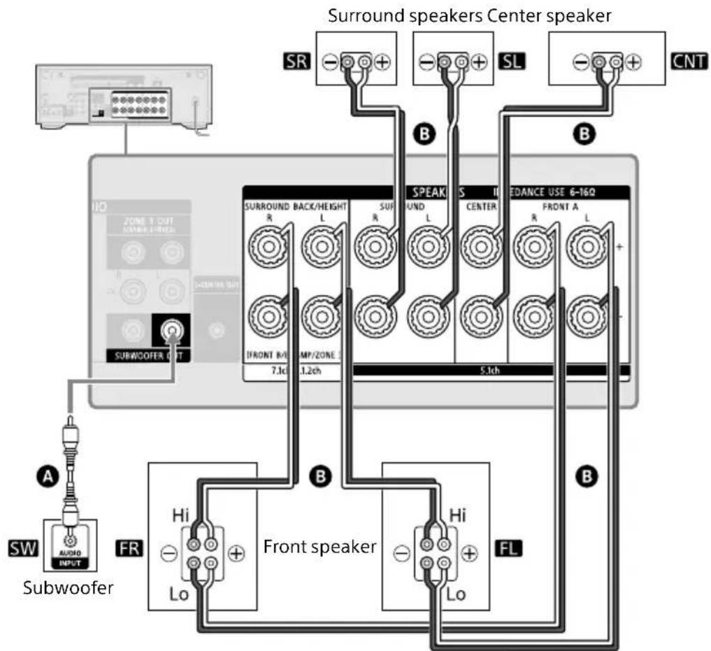
5.1-channel speaker system
flowchart
graph TD
    SW["SW"] --> FL["FL"]
    FL --> CNT["CNT"]
    CNT --> FR["FR"]
    SL["SL"] --> CNT
    SR["SR"] --> CNT
    CNT --> ①
    CNT --> ②
    ① --> ②
    ② --> ①
① 30^
② 100^ - 120^
flowchart
graph TD
    A["Subwoofer"] -->|A| B["SW"]
    B --> C["AVOID INPUT"]
    C --> D["SUBwoofer OUT"]
    D --> E["Surround speakers"]
    E --> F["SUR R"]
    E --> G["SUR L"]
    E --> H["SUR SL"]
    E --> I["SUR B"]
    E --> J["SUR S"]
    K["Front speakers"] --> L["FR"]
    K --> M["FL"]
    K --> N["FR"]
    K --> O["FL"]
    K --> P["FR"]
    K --> Q["FL"]
    K --> R["FR"]
    K --> S["FL"]
    K --> T["FR"]
    K --> U["FL"]
    K --> V["FR"]
    K --> W["FL"]
    K --> X["FR"]
    K --> Y["FL"]
    K --> Z["FR"]
    K --> AA["FL"]
A Monaural audio cable (not supplied)
B Speaker cable (not supplied)
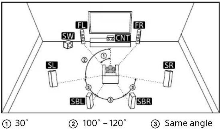
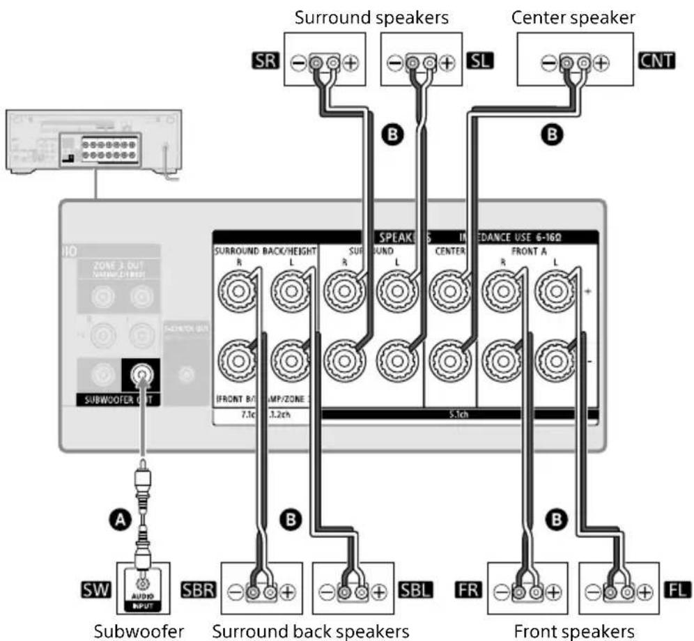
7.1-channel speaker system using surround back speakers
flowchart
graph TD
    A["Subwoofer"] -->|A| B["SW"]
    A -->|A| C["SBR"]
    A -->|B| D["Surround back speakers"]
    A -->|B| E["SBL"]
    A -->|B| F["FR"]
    A -->|B| G["FL"]
    H["SUBWOOFER OUT"] --> I["Switch"]
    J["Surround speakers"] --> K["SR"]
    J --> L["SL"]
    M["Center speaker"] --> N["CNT"]
    O["SURROUND BACK/HEIGHT"] --> P["R"]
    Q["SURROUND"] --> R["L"]
    S["SURROUND"] --> T["R"]
    U["SURROUND"] --> V["L"]
    W["SURROUND"] --> X["L"]
    Y["SURROUND"] --> Z["L"]
    AA["SURROUND"] --> AB["L"]
    AC["SURROUND"] --> AD["L"]
    AE["SURROUND"] --> AF["L"]
    AG["SURROUND"] --> AH["L"]
    AI["SURROUND"] --> AJ["L"]
    AK["SURROUND"] --> AL["L"]
    AM["SURROUND"] --> AN["L"]
    AO["SURROUND"] --> AP["L"]
    AQ["SURROUND"] --> AR["L"]
    AS["SURROUND"] --> AT["L"]
    AU["SURROUND"] --> AV["L"]
    AW["SURROUND"] --> AX["L"]
    AY["SURROUND"] --> AZ["R"]
    BA["SURROUND"] --> BB["R"]
    BC["SURROUND"] --> BD["R"]
    BE["SURROUND"] --> BF["R"]
    BG["SURROUND"] --> BH["R"]
    BI["SURROUND"] --> BJ["R"]
    BK["SURROUND"] --> BL["R"]
    BM["SURROUND"] --> BN["R"]
    BO["SURROUND"] --> BP["R"]
    BQ["SURROUND"] --> BR["R"]
    BS["SURROUND"] --> BT["R"]
    BU["SURROUND"] --> BV["R"]
    BW["SURROUND"] --> BX["R"]
    BY["SURROUND"] --> BZ["R"]
    CA["SURROUND"] --> CB["R"]
    CC["SURROUND"] --> CD["R"]
    DD["SURROUND"] --> DE["R"]
    DF["SURROUND"] --> DG["R"]
    DH["SURROUND"] --> DI["R"]
    DJ["SURROUND"] --> DK["R"]
    DL["SURROUND"] --> DV["R"]
    DW["SURROUND"] --> DX["R"]
    DX --> DW
    DB["SURROUND"] --> DC["R"]
    DC --> DV
    DB --> DW
    DB --> DX
    DB --> DV
    DB --> DX
    DB --> DW
    DB --> DX
    DB --> DX
    DB --> DW
    DB --> DX
    DB --> DX
    DB --> DW
    DB --> DX
    DB --> DX
    DB --> DW
    DB --> DX
    DB --> DX
    DB --> DW
    DB --> DX
    DB --> DX
    DB --> DW
    DB --> DX
    DB --> DX
    DB --> DW
    DB --> DX
    DB --> DX
    DB --> DX
    DB --> DW
    DB --> DX
    DB --> DX
    DB --> DX
    DB --> DW
    DB --> DX
    DB --> DX
    DB --> DX
A Monaural audio cable (not supplied)
B Speaker cable (not supplied)
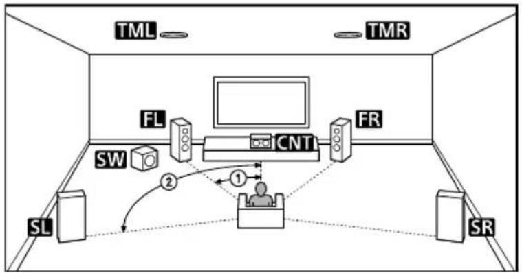
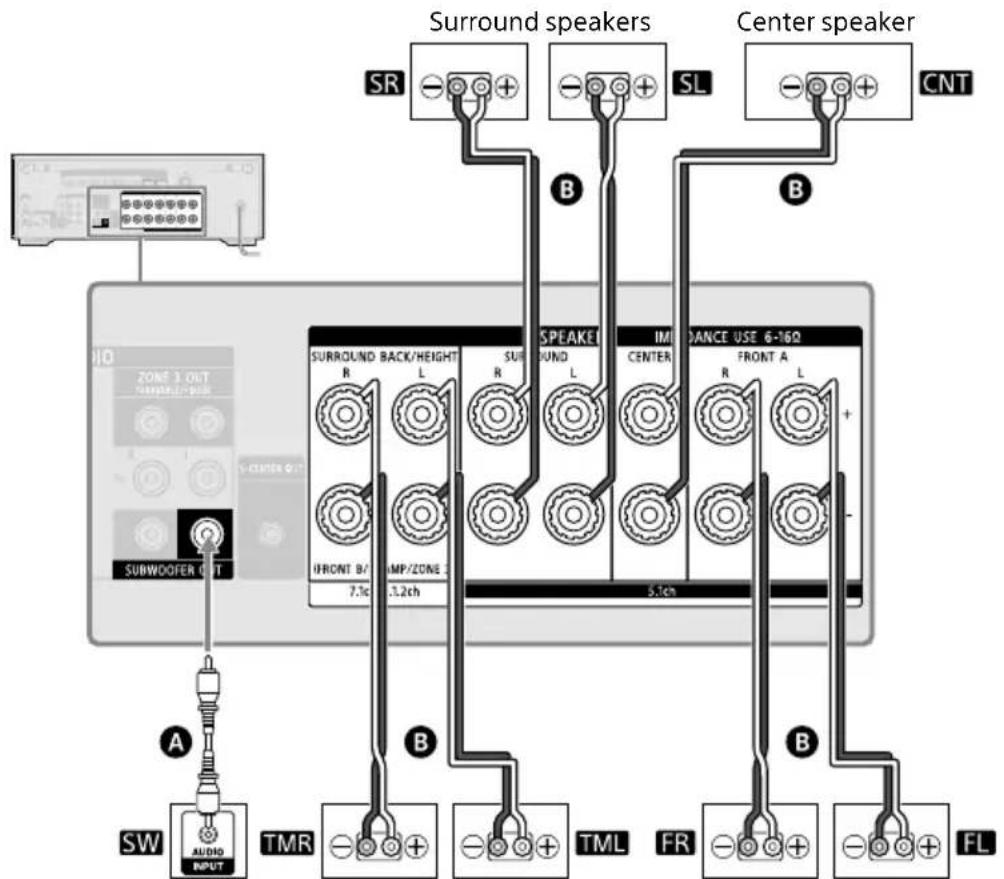
5.1.2-channel speaker system using top middle speakers
flowchart
graph TD
    TV["TV"] --> FL["FL"]
    FL --> CNT["CNT"]
    CNT --> FR["FR"]
    FL --> SW["SW"]
    SW --> 2["2"]
    2 --> 1["1"]
    1 --> SL["SL"]
    1 --> SR["SR"]
    1 --> TML["TML"]
    1 --> TMR["TMR"]
① 30^
② 100^-120^
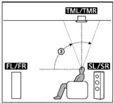
flowchart
graph TD
    A["TML/TMR"] --> B["FL/FR"]
    A --> C["SL/SR"]
    D["③"] --> A
    style A fill:#f9f,stroke:#333
    style B fill:#ccf,stroke:#333
    style C fill:#cfc,stroke:#333
③ 70^-110^
flowchart
graph TD
    A["Subwoofer CHT"] -->|A| B["SW"]
    B --> C["AUDIO INPUT"]
    C --> D["TMR"]
    D --> E["SURROUND BACK/HEIGHT R L"]
    E --> F["IMMANCE USE 6-16Ω CENTER R L"]
    F --> G["TML"]
    G --> H["FR"]
    H --> I["FL"]
    I --> J["Center speaker CNT"]
    K["SR"] --> L["+"]
    M["SL"] --> N["+"]
    O["B"] --> P["+"]
    Q["B"] --> R["+"]
    S["B"] --> T["+"]
    U["B"] --> V["+"]
    W["B"] --> X["+"]
Subwoofer
Top middle speakers*
Front speakers
A Monaural audio cable (not supplied)
B Speaker cable (not supplied)
* After you have made the connection, set [Speaker Pattern] in [Manual Speaker Settings] under [Speaker Settings] to [5.1.2 (TM)].
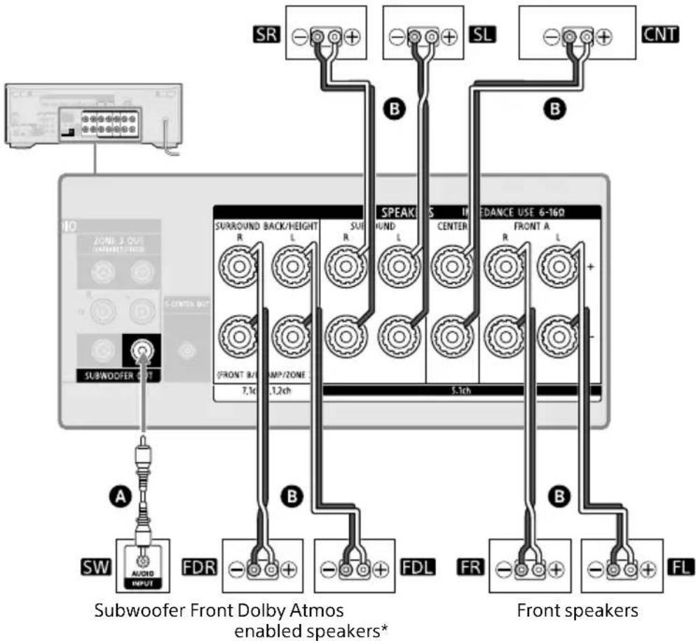
5.1.2-channel speaker system using Dolby Atmos enabled speakers
Surround speakers Center speaker
flowchart
graph TD
    A["SW"] --> B["AUDIO INPUT"]
    B --> C["Subwoofer"]
    C --> D["FDR"]
    D --> E["SURROUND BACK/HEIGHT R L SUI R"]
    E --> F["FRONT 8/MP/ZONE 7.1c 1.2ch"]
    F --> G["SPEAK ROUND L CENTER"]
    G --> H["5.3ch"]
    H --> I["FRONT A L"]
    I --> J["FL"]
    J --> K["Front speakers"]
    K --> L["SL"]
    L --> M["CNT"]
    M --> N["SR"]
    N --> O["-"]
    O --> P["+"]
    P --> Q["B"]
    Q --> R["+"]
    R --> S["SL"]
    S --> T["-"]
    T --> U["+"]
    U --> V["B"]
    V --> W["+"]
    W --> X["SL"]
    X --> Y["CNT"]
A Monaural audio cable (not supplied)
B Speaker cable (not supplied)
* After you have made the connection, set [Speaker Pattern] in [Manual Speaker Settings] under [Speaker Settings] to [5.1.2 (FD)].
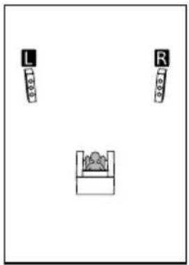
5.1-channel speaker system with Zone 3 speakers
Main zone
flowchart
graph TD
    A["SL"] --> B["Central Device"]
    C["SR"] --> B
    D["FR"] --> B
    E["CNT"] --> B
    F["SW"] --> B
    G["FL"] --> B
    H["①"] --> B
    I["②"] --> B
Zone 3
natural_image
Simple line drawing of a room with two labeled items (L and R) and a central object, no text or symbols present.① 30^
② 100^-120^
Surround speakers Center speaker

Subwoofer Speakers (Zone 3)* Front speakers
A Monaural audio cable (not supplied)
B Speaker cable (not supplied)
* For details on using the Zone 3 speakers, see "Using the Multi-Zone Features" (page 45).
5.1-channel speaker system with Bi-Amplifier connection
When the front speakers are Bi-wire speakers, which are equipped with separate terminals for high-frequency sounds (tweeter) and low-frequency sounds (woofer), you can make the bi-amplifier connection. Connect each pair of terminals for tweeter and woofer to the SPEAKERS FRONT A terminals and SPEAKERS SURROUND BACK/HEIGHT terminals of this receiver. You can enjoy higher quality sound playback if you operate the tweeter and woofer using separate amplifiers.
flowchart
graph TD
    A["Subwoofer"] -->|SW| B["Switch"]
    B --> C["Subwoofer INPUT"]
    C --> D["Switch"]
    D --> E["FR"]
    E --> F["Front speaker"]
    F --> G["FL"]
    G --> H["FR"]
    H --> I["SURROUND BACK/HEIGHT"]
    I --> J["R"]
    I --> K["L"]
    I --> L["SURFUND"]
    L --> M["R"]
    L --> N["L"]
    L --> O["SPEAK"]
    O --> P["SURFUND"]
    P --> Q["R"]
    P --> R["L"]
    P --> S["S CENTER"]
    S --> T["SURFUND"]
    T --> U["R"]
    T --> V["L"]
    T --> W["SPEAK"]
    W --> X["SURFUND"]
    X --> Y["R"]
    X --> Z["L"]
    X --> AA["SPEAK"]
    AA --> AB["SURFUND"]
    AB --> AC["R"]
    AB --> AD["L"]
    AB --> AE["SPEAK"]
    AE --> AF["SURFUND"]
    AF --> AG["R"]
    AF --> AH["L"]
    AF --> AI["SPEAK"]
    AI --> AJ["SURFUND"]
    AJ --> AK["R"]
    AJ --> AL["L"]
    AJ --> AM["SPEAK"]
    AM --> AN["SURFUND"]
    AN --> AO["R"]
    AN --> AP["L"]
    AN --> AQ["SPEAK"]
    AQ --> AR["SURFUND"]
    AR --> AS["R"]
    AR --> AT["L"]
    AR --> AU["SPEAK"]
    AU --> AV["SURFUND"]
    AV --> AW["R"]
    AV --> AX["L"]
    AV --> AY["SPEAK"]
    AY --> AZ["SURFUND"]
    AZ --> BA["R"]
    AZ --> BB["L"]
    AZ --> BC["SPEAK"]
    BC --> BD["SURFUND"]
    BD --> BE["R"]
    BE --> BF["L"]
    BE --> BG["SPEAK"]
    BG --> BH["SURFUND"]
    BH --> BI["R"]
    BH --> BJ["L"]
    BH --> BK["SPEAK"]
    BK --> BL["SURFUND"]
    BL --> BM["R"]
    BL --> BN["L"]
    BL --> BO["SPEAK"]
    BO --> BP["SURFUND"]
    BP --> BQ["R"]
    BP --> BR["L"]
    BP --> BS["SPEAK"]
    BS --> BT["SURFUND"]
    BT --> BU["R"]
    BT --> BV["L"]
A Monaural audio cable (not supplied)
B Speaker cable (not supplied)
Make sure that metal fittings of Hi/Lo attached to the speakers have been removed from the speakers to avoid receiver malfunction.
After you have made the connection, set [Surround Back Speaker Assign] in [Manual Speaker Settings] under [Speaker Settings] to [BI-AMP].
Note
You can only set [Surround Back Speaker Assign] if the speaker pattern is set to a setting that does not have surround back and height/overhead speakers (page 18).
Connecting to Sony wireless rear speaker/subwoofer
The receiver is compatible with connection to Sony wireless rear speaker/subwoofer (not supplied).
When you connect the wireless rear speaker/subwoofer to the receiver for the first time, follow the steps below.
Once connected, the Sony wireless rear speaker/subwoofer will be automatically connected to the receiver the next time you turn on the power.
1 Press HOME.
The home menu is displayed on the TV screen.
2 Select [Setup] – [Speaker Settings] – [Wireless Speaker Settings] – [Start manual linking].
3 Press LINK on the speaker (not supplied).
The power indicator of the speaker (not supplied) flashes twice repeatedly in green.
4 Select [Start].
The manual connection starts. The connecting process appears on the TV screen. To cancel the manual connection, select [Cancel].
5 When [Connected] is displayed for the target speakers, select [Finish].
6 Press⊕(enter).
The manual connection is established and the power indicator of the speaker (not supplied) lights in green.
7 Follow the on-screen instructions to perform Auto Calibration.
When the connection settings of wireless speakers are complete, a screen that guides you to [Auto Calibration] is displayed.
When you connect a wireless rear speaker, select either [Surround Speaker] or [Surround Back Speaker] on the [Wireless Speaker Assign] screen in Auto Calibration to assign the speaker position.
Tip
- For the wireless rear speaker/subwoofer models compatible with the receiver, visit the Sony website.
- If you connect 2 wireless subwoofers, use the same model.
- For details on the wireless rear speaker/subwoofer, refer to the operating instructions supplied with each speaker.
If wireless transmission is unstable
If you use multiple wireless systems, such as a wireless LAN, the wireless signals may become unstable. In this case, the transmission may be improved by changing the following setting.
1 Press HOME.
The home menu is displayed on the TV screen.
2 Select [Setup] - [Speaker Settings] - [Wireless Speaker Settings] - [RF Channel].
3 Select the setting you want.
- [On]: Normally select this. The receiver automatically selects the better channel for transmission. A stronger mode for wireless interference.
- [Off]: The receiver selects a channel from the limited frequency band to prevent external wireless interference. If sound dropping occurs while [On] is selected, it may be improved by selecting [Off].
Note
If you change the [RF Channel] setting from [Off] to [On], it may take 1 minute to reconnect.
Connecting a TV
Connect a TV to the HDMI OUT or MONITOR OUT jack.
The menu is displayed on the TV screen only when you connect the TV to the HDMI OUT jack.
Sony recommends that you use the HDMI OUT jack to connect the TV because in many cases you will have to perform the settings of this receiver using the menu.
Notes on connection
- Before connecting cables, be sure to disconnect the AC power cord (mains lead).
- Depending on the status of the connection between the TV and the antenna (aerial), the image on the TV screen may be distorted. If this is the case, place the antenna (aerial) farther away from the receiver.
- When connecting an optical digital cable, insert the plugs straight until they click into place.
- Do not bend or tie optical digital cables.
- All of the digital audio jacks are compatible with 32 kHz, 44.1 kHz, 48 kHz, and 96 kHz sampling frequencies.
- When connecting TV audio output to the receiver via the AUDIO IN TV (L/R) jacks, set the audio output level of the TV to "Fixed" if it can be switched between "Fixed" or "Variable."
- When you connect the TV to HDMI OUT B/ZONE 2 jack, be sure to set [HDMI OUT B Mode] to [Main] in the [HDMI Settings] menu. Press HDMI OUT repeatedly on the remote control to select "HDMI B" or "HDMI A+B." The home menu is not displayed on the TV screen if [HDMI OUT B Mode] is set to [Zone2].
- When you connect a TV compatible with the eARC or ARC function, turn on the eARC or ARC function and connect the eARC/ARC-compatible HDMI input jack of your TV to HDMI OUT A (TV) jack of the receiver (page 29).
HDMI cables
- Be sure to use a Premium High Speed HDMI Cable with Ethernet, which supports bandwidths up to 18 Gbps. For video signals that require a high bandwidth such as 4K/120p, 8K, etc., be sure to use an Ultra High Speed HDMI Cable that supports bandwidths up to 48 Gbps.
- Select an HDMI signal format suitable for video signal band of TV or AV devices to be connected with the HDMI cable in the menu on the receiver. For details on the HDMI signal format setting, visit the Help Guide.
- We do not recommend using an HDMI-DVI conversion cable. If you connect an HDMI-DVI conversion cable to a DVI-D device, the sound and/or image may be lost. Connect separate audio cables or digital connecting cables, then reassign the input jacks if the sound is not output correctly.
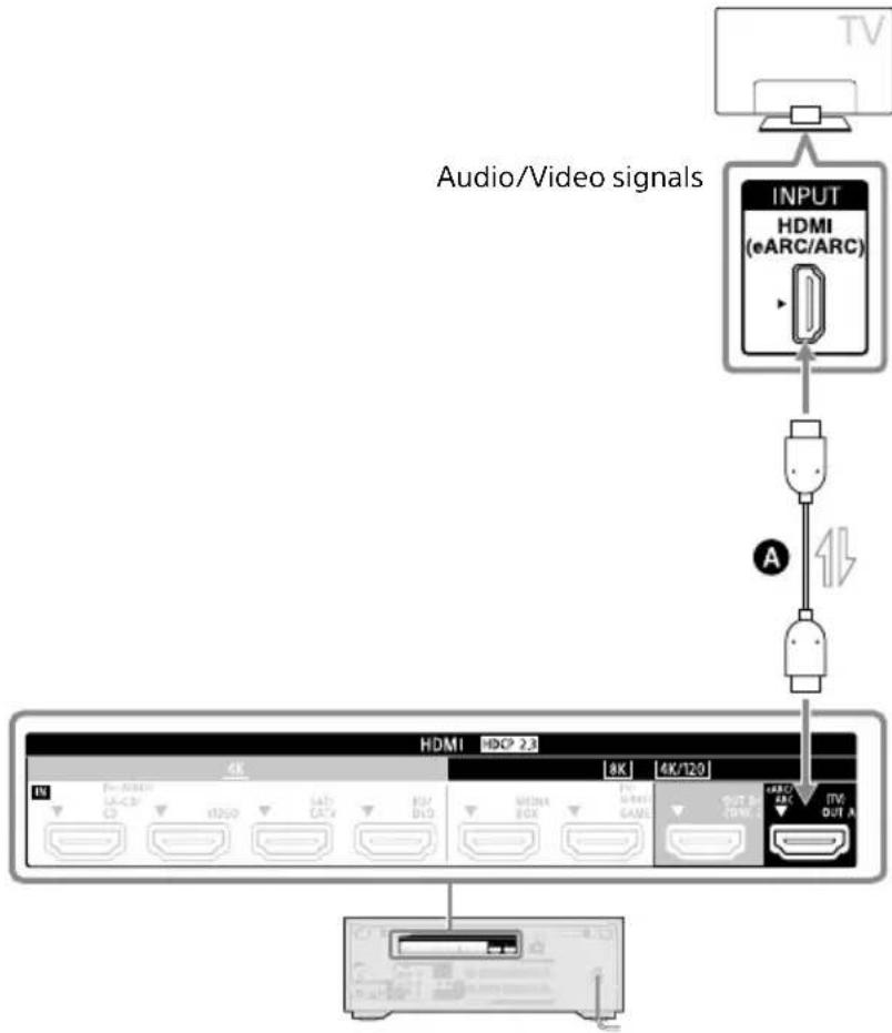
Connecting a TV compatible with the eARC or ARC function via an HDMI connection
Connect your TV to the HDMI OUT A (TV) jack of the receiver.
With just one HDMI cable connection, you can listen to the TV audio from the speakers connected to the receiver while the receiver sends audio and video signals to the TV.
flowchart
graph TD
    A["TV"] --> B["INPUT HDMI (eARC/ARC)"]
    B --> C["USB"]
    C --> D["4K/120"]
    D --> E["4K/8K/20K/4K/8K/20K/4K/8K/20K/4K/8K/20K/4K/8K/20K/4K/8K/20K/4K/8K/20K/4K/8K/20K/4K/8K/20K/4K/8K/20K/4K/8K/20K"]
    E --> F[Output 4K/8K/20K/4K/8K/20K/4K/8K/20K/4K/8K/20K/4K/8K/20K/4K/8K/20K/4K/8K/20K/4K/8K/20K/4K/8K/20K/4K/8K/20K, 4K/8K/20K/4K/8K/20K/4K/8K/20K/4K/8K/20K, 4K/8K/20K/4K/8K/20K/4K/8K/20K, 4K/8K/20K/4K/8K/20K, 4A, 11, 11, 11, 11, 11, 11, 11, 11, 11, 11, 11, 11, 11, 11, 11, 11, 11, 11, 11, 11, 11, 11, 11, 11, 11, 10, 10, 10, 10, 10, 10, 10, 10, 10, 10, 10, 10, 10, 10, 10, 10, 10, 10, 10, 10, 10, 10, 10, 10, 10, 15, 20, 30, 40, 50, 60, 70, 80, 90, 100, 110, 120, 130, 140, 150, 160, 170, 180, 190, 200, 210, 220, 230, 240, 250, 260, 270, 280, 290, 300, 310, 320, 330, 340, 350, 360, 370, 380, 390, 400, 410, 420, 430, 440, 450, 460, 470, 480, 490, 500, 510, 520, 530, 540, 550, 560, 570, 580, 590, 600, 610, 620, 630, 640, 650, 660, 670, 680, 690, 700, 710, 720, 730, 740, 750, 760, 770, 780, 790, 800, 810, 820, 830, 840, 850, 860, 870, 880, 890, 900, 910, 920, 930, 940, 950, 960, 970, 980, 990, 1000 |
A HDMI cable (not supplied)
Note
- To use your TV with this connection, you need to turn the eARC or ARC function on. Press HOME, then select [Setup] - [HDMI Settings] - [Audio Return Channel] - [eARC] or [ARC].
- You also need to perform the setting on the TV menu. Turn on the eARC or ARC function.
Tip
If the HDMI jack of the TV (labeled "eARC" or "ARC") is already connected to another device, disconnect the device and connect the receiver.
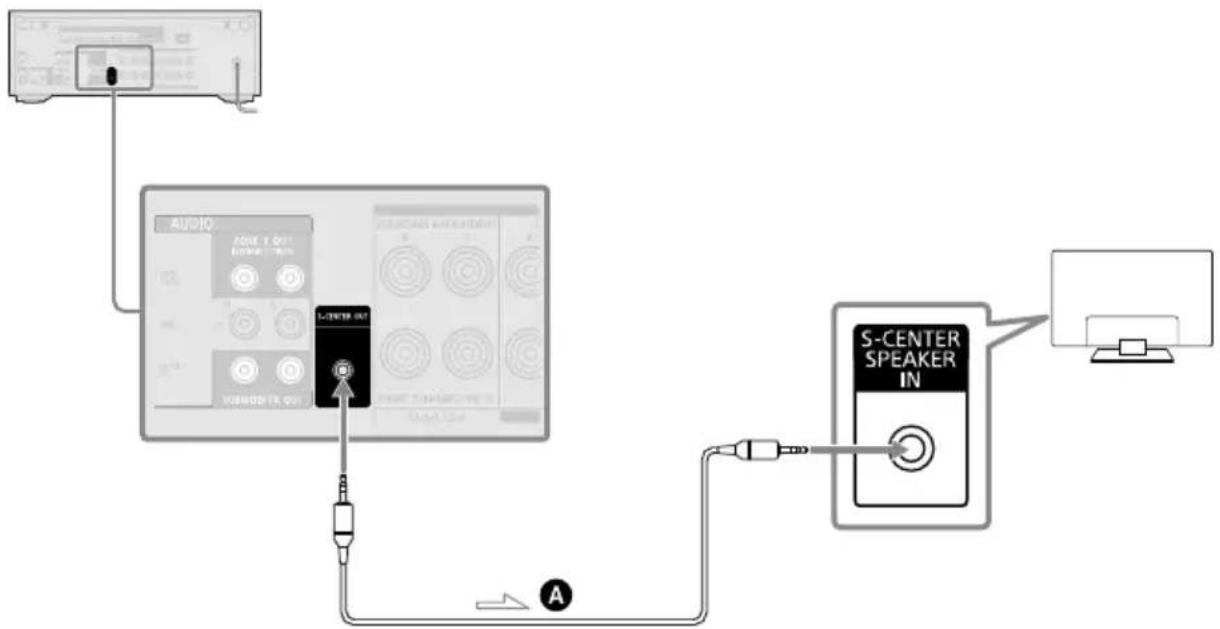
When your TV has the S-CENTER SPEAKER IN jack
When the receiver is connected to the S-CENTER SPEAKER IN jack of your TV, you can output the center part of the receiver sound from the TV speakers. By using this connection, TV audio such as dialogue can be made to sound as if it is coming out of the TV screen. (Acoustic Center Sync function)
To use this function, you need to connect your TV to the HDMI OUT A (TV) jack of the receiver.
Also, set [TV Center Speaker] to [Use TV as Center] in Auto Calibration.
flowchart
graph TD
    A["Input"] --> B["AUDIO"]
    B --> C["S-CENTER IN"]
    C --> D["S-CENTER SPEAKER IN"]
    D --> E["Output"]
A Stereo 3-pole mini plug audio cable (not supplied)
Note
- When [Sound Field] is set to [2ch Stereo], the sound will not be output through the TV speaker.
- Depending on the sound source, the sound may not be output through the TV speaker.
- When a BLUETOOTH device is connected and [Bluetooth Mode] is set to [Transmitter], or a headphone is connected, the sound will not be output through the TV speaker.
Tip
- Some Sony TVs have an S-CENTER SPEAKER IN jack. For details, see the operating instructions of your TV.
- If you connect your TV to the S-CENTER OUT jack of the receiver, press HOME, select [Setup] - [Speaker Settings] - [TV/Screen Center Settings] - [TV Center Speaker Mode] and then set to [On].
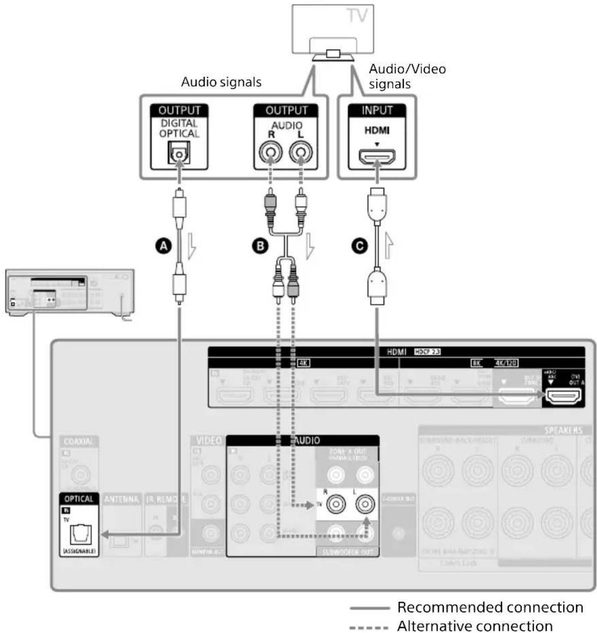
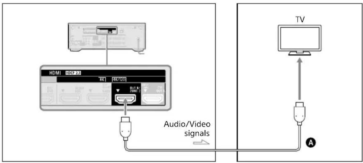
Connecting a TV incompatible with the eARC and ARC functions via an HDMI connection
Connect your TV to the HDMI OUT A (TV) jack of the receiver.
When you connect the receiver to a TV using the HDMI cable Ⓓ, the receiver can output audio and video signals to the TV. Note, however, that you also need to connect the optical digital cable A or audio cable B to the TV in order to output TV audio from the speakers connected to the receiver.
flowchart
graph TD
    TV["TV"] --> Audio1["Audio signals"]
    Audio1 --> DigitalOptical["OUTPUT DIGITAL OPTICAL"]
    Audio1 --> Audio2["OUTPUT AUDIO R L"]
    Audio1 --> Audio3["INPUT HDMI"]
    DigitalOptical --> Audio4["Audio Signal A"]
    Audio2 --> Audio5["Audio Signal B"]
    Audio3 --> Audio6["Audio Signal C"]
    Audio4 --> HDMI["HD/CP 23 HDMI"]
    Audio5 --> HDMI
    Audio6 --> HDMI
    Audio4 --> Audio7["VIDEO"]
    Audio5 --> Audio8["VIDEO"]
    Audio6 --> Audio9["VIDEO"]
    Audio4 --> Audio10["SLW/OODER OUT"]
    Audio5 --> Audio11["SLW/OODER OUT"]
    Audio6 --> Audio12["SLW/OODER OUT"]
    Audio4 --> Audio13["SLW/OODER OUT"]
    Audio5 --> Audio14["SLW/OODER OUT"]
    Audio6 --> Audio15["SLW/OODER OUT"]
    Audio4 --> Audio16["SLW/OODER OUT"]
    Audio5 --> Audio17["SLW/OODER OUT"]
    Audio6 --> Audio18["SLW/OODER OUT"]
    Audio4 --> Audio19["SLW/OODER OUT"]
    Audio5 --> Audio20["SLW/OODER OUT"]
    Audio6 --> Audio21["SLW/OODER OUT"]
    Audio4 --> Audio22["SLW/OODER OUT"]
    Audio5 --> Audio23["SLW/OODER OUT"]
    Audio6 --> Audio24["SLW/OODER OUT"]
    Audio4 --> Audio25["SLW/OODER OUT"]
    Audio5 --> Audio26["SLW/OODER OUT"]
    Audio6 --> Audio27["SLW/OODER OUT"]
    Audio4 --> Audio28["SLW/OODER OUT"]
    Audio5 --> Audio29["SLW/OODER OUT"]
    Audio6 --> Audio30["SLW/OODER OUT"]
    Audio4 --> Audio31["SLW/OODER OUT"]
    Audio5 --> Audio32["SLW/OODER OUT"]
    Audio6 --> Audio33["SLW/OODER OUT"]
    Audio4 --> Audio34["SLW/OODER OUT"]
    Audio5 --> Audio35["SLW/OODER OUT"]
    Audio6 --> Audio36["SLW/OODER OUT"]
    Audio4 --> Audio37["SLW/OODER OUT"]
    Audio5 --> Audio38["SLW/OODER OUT"]
    Audio6 --> Audio39["SLW/OODER OUT"]
    Audio4 --> Audio40["SLW/OODER OUT"]
    Audio5 --> Audio41["SLW/OODER OUT"]
    Audio6 --> Audio42["SLW/OODER OUT"]
    Audio4 --> Audio43["SLW/OODER OUT"]
    Audio5 --> Audio44["SLW/OODER OUT"]
    Audio6 --> Audio45["SLW/OODER OUT"]
A Optical digital audio cable (not supplied)
B Audio cable (not supplied)
© HDMI cable (not supplied)
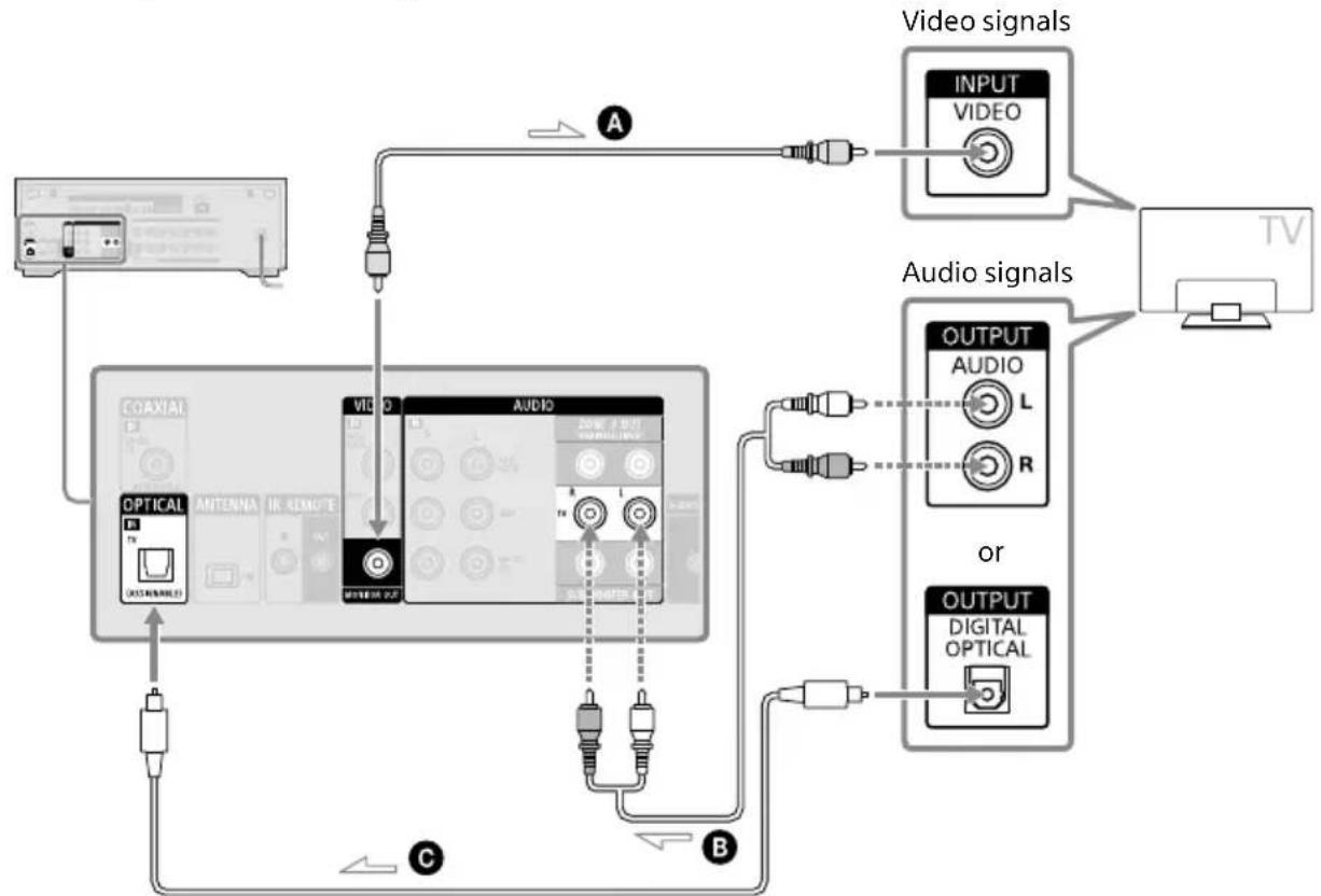
Connecting a TV without HDMI jacks
Connect your TV to the MONITOR OUT jack of the receiver.
You need to connect the optical digital audio cable Ⓒ or audio cable Ⓑ to the TV in addition to connecting the video cable Ⓔ.
flowchart
graph TD
    A["TV"] --> B["Audio signals"]
    B --> C["VIDEO"]
    C --> D["VIDEO"]
    D --> E["VIDEO"]
    E --> F["VIDEO"]
    F --> G["VIDEO"]
    G --> H["VIDEO"]
    H --> I["VIDEO"]
    I --> J["VIDEO"]
    J --> K["VIDEO"]
    K --> L["VIDEO"]
    L --> M["VIDEO"]
    M --> N["VIDEO"]
    N --> O["VIDEO"]
    O --> P["VIDEO"]
    P --> Q["VIDEO"]
    Q --> R["VIDEO"]
    R --> S["VIDEO"]
    S --> T["VIDEO"]
    T --> U["VIDEO"]
    U --> V["VIDEO"]
    V --> W["VIDEO"]
    W --> X["VIDEO"]
    X --> Y["VIDEO"]
    Y --> Z["VIDEO"]
    Z --> AA["VIDEO"]
    AA --> AB["VIDEO"]
    AB --> AC["VIDEO"]
    AC --> AD["VIDEO"]
    AD --> AE["VIDEO"]
    AE --> AF["VIDEO"]
    AF --> AG["VIDEO"]
    AG --> AH["VIDEO"]
    AH --> AI["VIDEO"]
    AI --> AJ["VIDEO"]
    AJ --> AK["VIDEO"]
    AK --> AL["VIDEO"]
    AL --> AM["VIDEO"]
    AM --> AN["VIDEO"]
    AN --> AO["VIDEO"]
    AO --> AP["VIDEO"]
    AP --> AQ["VIDEO"]
    AQ --> AR["VIDEO"]
    AR --> AS["VIDEO"]
    AS --> AT["VIDEO"]
    AT --> AU["VIDEO"]
    AU --> AV["VIDEO"]
    AV --> AW["VIDEO"]
    AW --> AX["VIDEO"]
    AX --> AY["VIDEO"]
— Recommended connection
Alternative connection
A Video cable (not supplied)
B Audio cable (not supplied)
© Optical digital audio cable (not supplied)
Note
- When you have connected the receiver and TV using the above method, video from the device connected to the VIDEO IN jacks is displayed on the TV.
- When you connect the receiver and TV using the above method, the menu is not displayed on the TV screen. To perform operations using the menu, you need to connect the TV via an HDMI connection.
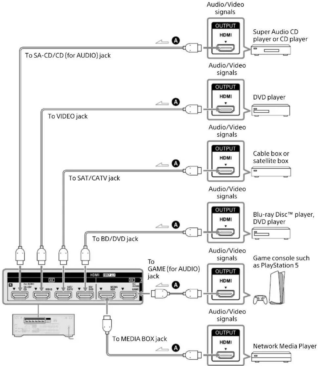
Connecting Audio-Visual Devices
Connecting devices with HDMI jacks
Before connecting cables, be sure to disconnect the AC power cord (mains lead).
The following illustrations are connection examples of devices. Connect to the HDMI jack compatible with the video signal of your device.
flowchart
graph TD
    A["To SA-CD/CD (for AUDIO) jack"] --> B["To VIDEO jack"]
    B --> C["To SAT/CATV jack"]
    C --> D["To BD/DVD jack"]
    D --> E["To GAME (for AUDIO) jack"]
    E --> F["To MEDIA BOX jack"]
    F --> G["Network Media Player"]

    H["Super Audio CD player or CD player"] --> I["OUTPUT HDMI"]
    J["DVD player"] --> K["OUTPUT HDMI"]
    L["Cable box or satellite box"] --> M["OUTPUT HDMI"]
    N["Blu-ray Disc™ player, DVD player"] --> O["OUTPUT HDMI"]
    P["Game console such as PlayStation 5"] --> Q["OUTPUT HDMI"]
    R["Network Media Player"] --> S["OUTPUT HDMI"]

    style A fill:#f9f,stroke:#333
    style B fill:#f9f,stroke:#333
    style C fill:#f9f,stroke:#333
    style D fill:#f9f,stroke:#333
    style E fill:#f9f,stroke:#333
    style F fill:#f9f,stroke:#333
    style G fill:#f9f,stroke:#333
    style H fill:#ccf,stroke:#333
    style I fill:#ccf,stroke:#333
    style J fill:#ccf,stroke:#333
    style K fill:#ccf,stroke:#333
    style L fill:#ccf,stroke:#333
    style M fill:#ccf,stroke:#333
    style N fill:#ccf,stroke:#333
    style O fill:#ccf,stroke:#333
    style P fill:#ccf,stroke:#333
    style Q fill:#ccf,stroke:#333
    style R fill:#ccf,stroke:#333
    style S fill:#ccf,stroke:#333
A HDMI cable (not supplied)
Video signals supported by HDMI jacks
This connection is an example. Connect to HDMI jacks that support the video signals of your device.
| HDMI IN jack Devices to be connected | ||
| SA-CD/CD (for AUDIO)* | 4K | Connect a device that supports video signals up to 4K/60p. |
| VIDEO* | ||
| SAT/CATV | ||
| BD/DVD | ||
| MEDIA BOX | 8K | Connect a device that supports video signals of 8K or up to 4K/120p. |
| GAME (for AUDIO) | 4K/120 | |
* When you connect your PC to this jack, supported video signals are limited to up to 4K/30p. Even in that case, you can enjoy 4K/60p video content by connecting your PC to SAT/CATV, BD/DVD, MEDIA BOX, or GAME (for AUDIO) jack.
Note
For the video signals that can be played in Zone 2, see "Selectable input and functional restriction in Zone 2 and Zone 3" (page 46).
Tip
- The image quality depends on the type of connecting jack. We recommend you connect your devices via an HDMI connection if they have HDMI jacks.
- If you want to watch 8K or 4K/120p video from your device even when the eARC/ARC-compatible HDMI input jack of your TV is incompatible with 8K or 4K/120p video input, visit the Help Guide for how to connect.
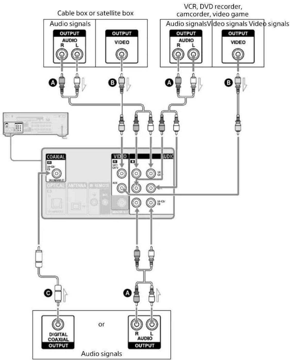
Connecting devices with jacks other than HDMI jacks
Before connecting cables, be sure to disconnect the AC power cord (mains lead).
flowchart
graph TD
    subgraph_Cable_box[" Cable box or satellite box "]
        A1["OUTPUT AUDIO R L"] --> A2["AC"]
        B1["OUTPUT VIDEO"] --> B2["AC"]
    end
    subgraph_Video_Camer["VCR, DVD recorder, camcorder, video game"]
        C1["OUTPUT AUDIO R L"] --> C2["AC"]
        D1["OUTPUT VIDEO"] --> D2["AC"]
    end
    subgraph_Audio_Serial[" Audio signals "]
        E1["COAXIAL IN: SA-CD/CD IN: SIGNALS"] --> E2["OPTICAL OUT: SAT/ CATV"]
        F1["VIDEO OUT: SA-CD/ CD"] --> F2["ALUX"]
        G1["DIGITAL COAXIAL OUTPUT"] --> G2["R AUDIO OUTPUT"]
    end
    H1["Audio signals"] --> I1["OR"]
    I1 --> J1["OR"]
    J1 --> K1["OR"]
    K1 --> L1["OR"]
    L1 --> M1["OR"]
    M1 --> N1["OR"]
    N1 --> O1["OR"]
    O1 --> P1["OR"]
    P1 --> Q1["OR"]
    Q1 --> R1["OR"]
    R1 --> S1["OR"]
    S1 --> T1["OR"]
    T1 --> U1["OR"]
    U1 --> V1["OR"]
    V1 --> W1["OR"]
    W1 --> X1["OR"]
    X1 --> Y1["OR"]
    Y1 --> Z1["OR"]
    Z1 --> AA1["OR"]
    AA1 --> AB1["OR"]
    AB1 --> AC1["OR"]
    AC1 --> AD1["OR"]
    AD1 --> AE1["OR"]
    AE1 --> AF1["OR"]
    AF1 --> AG1["OR"]
    AG1 --> AH1["OR"]
    AH1 --> AI1["OR"]
    AI1 --> AJ1["OR"]
    AJ1 --> AK1["OR"]
    AK1 --> AL1["OR"]
    AL1 --> AM1["OR"]
    AM1 --> AN["OR"]
    AN --> AO["OR"]
    AO --> AP1["OR"]
    AP1 --> AQ["OR"]
    AQ --> AR["OR"]
    AR --> AS["OR"]
    AS --> AT["OR"]
    AT --> AU["OR"]
    AU --> AV["OR"]
    AV --> AW["OR"]
    AW --> AX["OR"]
    AX --> AY["OR"]
    AY --> AZ["OR"]
    AZ --> BA["OR"]
    BA --> BB["OR"]
    BB --> BC["OR"]
    BC --> BD["OR"]
    BD --> BE["OR"]
    BE --> BF["OR"]
    BF --> BG["OR"]
    BG --> BH["OR"]
    BH --> BI["OR"]
    BI --> BJ["OR"]
    BJ --> BK["OR"]
    BK --> BL["OR"]
    BL --> BM["OR"]
    BM --> BN["OR"]
Super Audio CD player, CD player, Turntable*
A Audio cable (not supplied)
B Video cable (not supplied)
© Coaxial digital cable (not supplied)
* To connect a turntable that only has a PHONO output jack, you need to connect a phono equalizer (not supplied) between the turntable and this receiver.
Note
To listen to sound from a device connected to one of the AUDIO IN jacks, do not connect any device to the COAXIAL IN SA-CD/CD jack, the OPTICAL IN TV jack, or an HDMI IN jack labeled with the same device name (such as SAT/CATV, TV, or SA-CD/CD (for AUDIO)).
Tip
- You can connect devices other than those indicated above to the AUDIO IN jacks (SAT/CATV, AUX, and SA-CD/CD).
- You can rename each input whose name appears on the display panel of the receiver. For details, visit the Help Guide.
Connecting another amplifier or TV in Zone 2
HDMI input video/audio signals are output in Zone 2 using the HDMI OUT B/ZONE 2 jack of the receiver.
Before connecting cables, be sure to disconnect the AC power cord (mains lead).
When connecting to only TV in Zone 2
Main zone Zone 2
Recommended connection
Alternative connection
A HDMI cable (not supplied)
When connecting to an amplifier/receiver in Zone 2
Main zone Zone 2
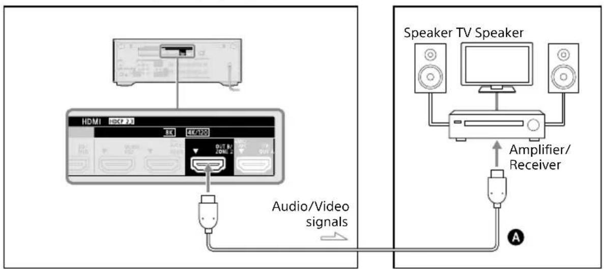
— Recommended connection
Alternative connection
A HDMI cable (not supplied)
Note
- To use this connection, set [HDMI OUT B Mode] in the [HDMI Settings] menu to [Zone2].
- You can only playback input from the HDMI IN jacks in Zone 2. When [SOURCE] is selected, the video and sound that are input from the HDMI IN jack selected in the main zone are played.
- You can only select an input from the HDMI IN jacks in Zone 2. Since the audio signals are output from the HDMI OUT B/ZONE 2 jack as they are, you cannot adjust the volume level on the receiver. Adjust the volume on the device connected to the HDMI OUT B/ZONE 2 jack.
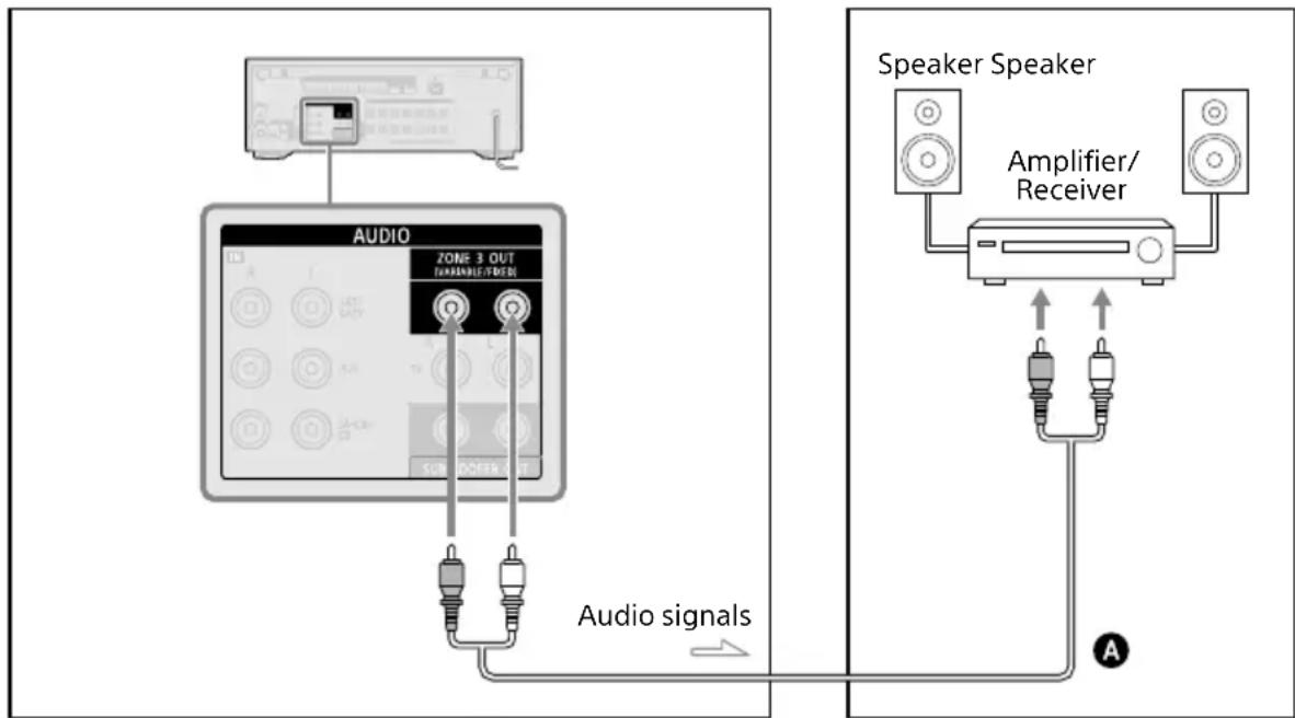
Connecting another amplifier in Zone 3
You can enjoy sound from a device connected to the receiver in a zone other than the main zone. For example, you can watch a DVD in the main zone and listen to a CD in Zone 3. Before connecting cables, be sure to disconnect the AC power cord (mains lead).
Main zone Zone 3
flowchart
graph TD
    A["Speaker Speaker"] -->|Amplifier/Receiver| B["Audio Signal"]
    B --> C["Audio Signals"]
    D["Audio"] --> E["Speaker Receiver"]
    style A fill:#f9f,stroke:#333
    style B fill:#ccf,stroke:#333
    style C fill:#cfc,stroke:#333
    style D fill:#fcc,stroke:#333
A Audio cable (not supplied)
Note
- To enjoy [USB], [Home Network], [Bluetooth Audio], [Chromecast built-in], [Spotify], or [AirPlay] in Zone 3, select [SOURCE] for the zone 3 input, then and switch the main zone input.
- You can select an input from four external inputs (SAT/CATV, AUX, TV, or SA-CD/CD), FM radio, and [SOURCE] in Zone 3. When one of the external inputs is selected, the audio of the device connected to the AUDIO IN jack is played. To play other inputs, such as Bluetooth Audio, or the external digital input from the OPTICAL IN TV jack, the COAXIAL IN SA-CD/CD jack, or the HDMI IN jacks, select the target input for the main zone, and then select [SOURCE] for Zone 3.
- If you set [DSD Native] in [Audio Settings] to [On], no audio signals for DSD content from [USB] or [Home Network] are output to the Zone 3 speakers.
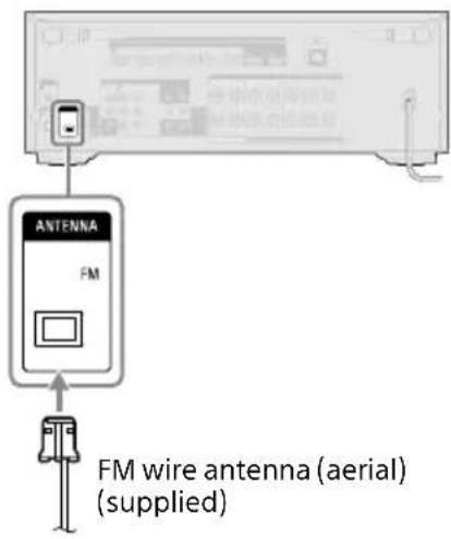
Connecting the Antenna (aerial)
Connect the supplied FM wire antenna (aerial) to the receiver as illustrated below. Before connecting the antenna (aerial), be sure to disconnect the AC power cord (mains lead).
Note
- Be sure to fully extend the FM wire antenna (aerial).
- After connecting the FM wire antenna (aerial), keep it as horizontal as possible.
Connecting to a Network
Select the connection method based on your LAN (Local Area Network) environment. The following illustrations are configuration examples of a home network with the receiver and a server.
When using wired LAN connection
We recommend that you connect the server to the router with a wired connection. Connect your receiver to the network using a LAN cable* (not supplied).
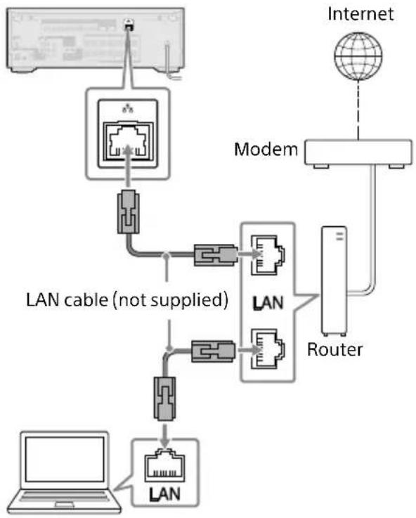
flowchart
graph TD
    A["Internet"] --> B["Modem"]
    B --> C["Router"]
    C --> D["LAN"]
    D --> E["LAN cable (not supplied)"]
    E --> F["Laptop"]
    G["Router"] --> H["Modem"]
    H --> I["Internet"]
    J["Internet"] --> K["Modem"]
    K --> L["Router"]
Server (computer, etc.)
* We recommend using category 7 cables.
When using wireless LAN connection
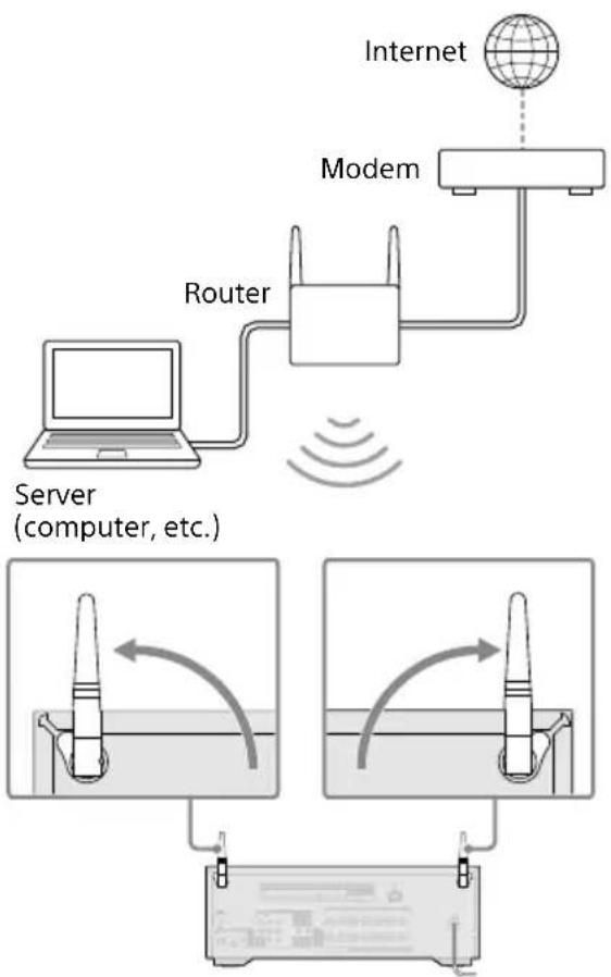
flowchart
graph TD
    A["Internet"] --> B["Modem"]
    B --> C["Router"]
    C --> D["Server (computer, etc.)"]
    D --> E["Test Tube 1"]
    D --> F["Test Tube 2"]
    E --> G["Output Signal"]
    F --> H["Output Signal"]
Note
• Audio playback on a server may occasionally be interrupted if you use a wireless connection.
- When using a wireless connection, stand up both wireless LAN antennas for better performance.
Preparing the Receiver
1 Insert batteries into the remote control (page 6).
2 Assemble the calibration mic stand (page 6).
3 Place the mic stand at your listening position and set the calibration microphone on the mic stand.
Adjust the position of the mic stand so that the calibration microphone is level with your ears.
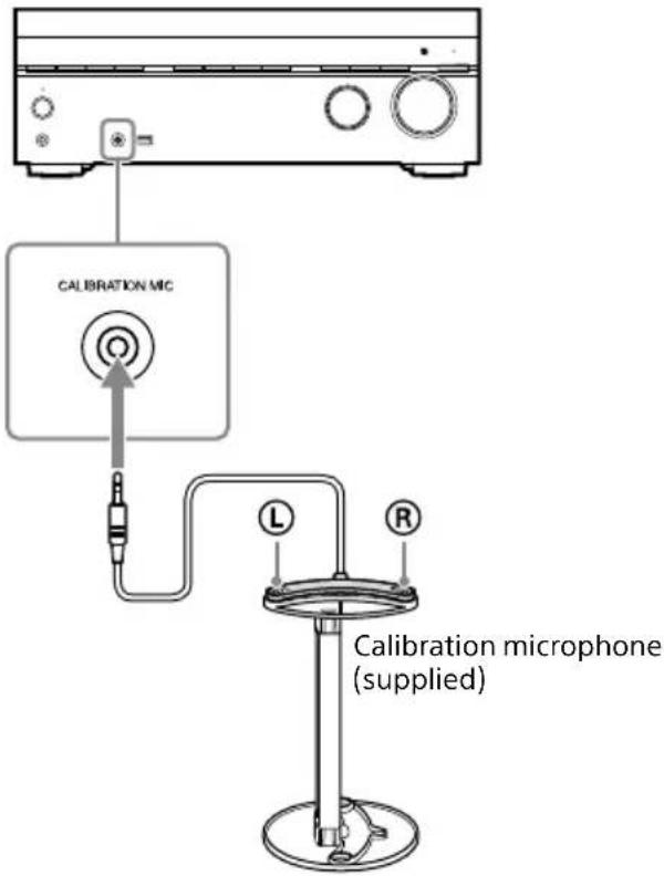
Note
- Fully insert the plug of the calibration microphone into the CALIBRATION MIC jack. If the calibration microphone is not firmly connected, it may not be possible to measure correctly.
• Install the calibration microphone horizontally so that L (left) and R (right) are at the same height.
4 Connect the AC power cord (mains lead) to a wall outlet.
Before connecting the AC power cord (mains lead), be sure to make connections for speakers and the other devices.
"HELLO" appears on the display panel and then switches to "PLEASEWAIT." You cannot turn on the receiver until the "PLEASEWAIT" display disappears.
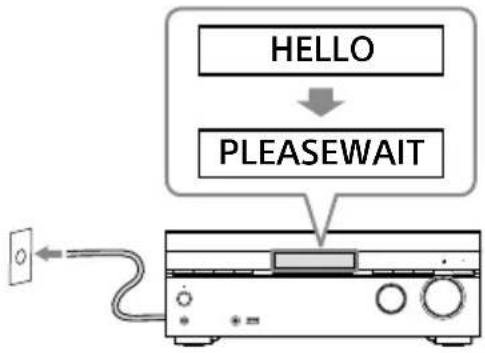
flowchart
graph TD
    A["HELLO"] --> B["PLEASEWAIT"]
    B --> C["Device"]
Setting up the Receiver using the Easy Setup
When you turn on the receiver for the first time or after the receiver is initialized, the Easy Setup screen appears on the TV screen.
Note
It is not possible to perform the Easy Setup procedure using the indications on the front display panel.
1 Turn on the TV, and then switch the input of the TV to the receiver.
2 Press ⏻ (power) to turn on the receiver.
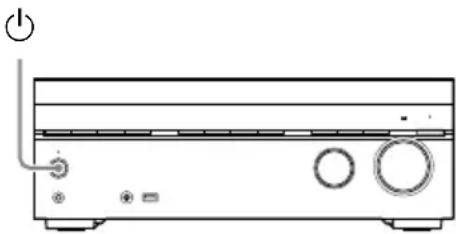
natural_image
Line drawing of a portable electronic device with buttons and a power switch (no text or symbols)You can also turn on the receiver using ⏻ (power) on the remote control.
3 Follow the on-screen instructions to select items using √ ↗ ↗, and confirm with ⊕
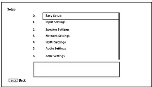
If the Easy Setup screen does not appear or you want to display the Easy Setup screen manually, you can display it by pressing HOME, then select [Setup] – [Easy Setup].
What you can do with Easy Setup
By performing Easy Setup, you can complete:
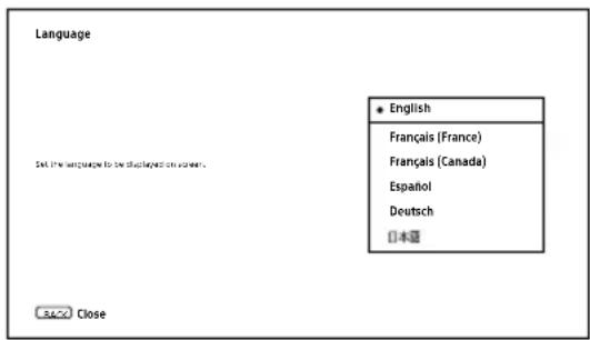
1: Language selection
2: Auto Calibration
Check your speaker system and perform Auto Calibration according to the configuration and arrangement of your speaker system.
3: Internet Settings
Select the network connection method and configure settings to connect the receiver to the network.
Performing Auto Calibration (D.C.A.C. IX)
Before you perform Auto Calibration
- Disconnect the headphones.
- Remove any obstacles between the calibration microphone and the speakers.
- When [Bluetooth Mode] is set to [Transmitter], cancel the setting before performing Auto Calibration.
- For accurate measurement, make sure the environment is quiet and free from noise.
- Set the speaker output to a setting other than "SPK OFF." See "Selecting the front speakers" (page 43).
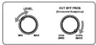
- Confirm the subwoofer setup
- Before using a subwoofer, turn on the subwoofer and turn up the volume. Turn the LEVEL to just before the mid-point.
- When a subwoofer with a crossover frequency function is connected, set the value to maximum.
- When a subwoofer with an auto standby function is connected, set it to off (deactivated).
Note
Depending on the characteristics of the subwoofer you are using, the setup distance value may be different from the actual position.
Auto Calibration operation
Auto Calibration is performed twice.
- 1st calibration: Place the microphone on the mic stand top (①).
- 2nd calibration: Rotate the microphone 90 degrees and place it on the mic stand bottom (②).
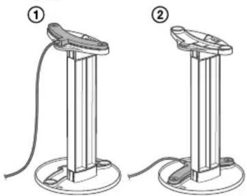
natural_image
Two identical mechanical device setups with a cable and base, labeled ① and ② (no text or symbols on the devices themselves)Note
- The speakers emit very loud sound during the calibration and the volume cannot be adjusted. Be considerate of your neighbors and any children who are present.
- If the muting function has been activated before you perform Auto Calibration, the muting function will shut off automatically.
- It may not be possible to take the correct measurements or to perform Auto Calibration at all if special speakers such as dipole speakers are used.
- If the measurement fails, follow the message, then select [Retry]. For details on the error code and warning message, see "List of messages after Auto Calibration measurements" (page 59).
To cancel Auto Calibration
The Auto Calibration function will be canceled when you perform the following operations, etc. during the measurement process:
- Press ⏻ (power).
- Press the input buttons on the remote control or turn the INPUT SELECTOR on the receiver.
- Press ☒ (muting), HOME, AMP MENU or HDMI OUT.
- Press SPEAKERS on the receiver.
- Change the volume level.
- Connect the headphones.
For details on Auto Calibration, visit the Help Guide.
Selecting the front speakers
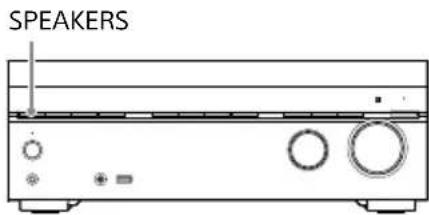
Press SPEAKERS repeatedly.
The indicators on the display panel shows which set of terminals are selected.
- SPA: Speakers connected to the SPEAKERS FRONT A terminals.
- SPB*: Speakers connected to the SPEAKERS SURROUND BACK/HEIGHT (FRONT B/BI-AMP/ZONE 3) terminals.
- SPA+B*: Speakers connected to both the SPEAKERS FRONT A and SPEAKERS SURROUND BACK/HEIGHT (FRONT B/BI-AMP/ZONE 3) terminals (parallel connection).
- (None): "SPK OFF" appears on the display panel. No audio signals are output from any speaker terminals.
* To select "SPB" or "SPA+B", set [Surround Back Speaker Assign] in [Speaker Settings] to [Front B].
Note
This setting is not available when headphones are connected.
Listening/Watching
Playing AV devices/ Listening to FM radio
You can connect AV devices to the receiver to enjoy a wide range of content such as movies and audio.
Also, you can listen to FM broadcasts in high-quality sound through the built-in tuner.
1 Turn on the device you want to play.
2 Turn on the receiver.
3 Turn the TV on, and then switch the input of the TV to the input to which the receiver is connected.
4 Press HOME.
The home menu is displayed on the TV screen.
Depending on the TV, the home menu may take some time to appear on the TV screen.
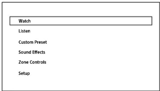
5 Press ✦ to select [Watch] or [Listen], then press
The menu item list appears on the TV screen.
6 Select the device you want to play and start playback.
When you select an input other than the external input, such as [FM TUNER], follow the instructions on the TV screen. For details on operation, visit the Help Guide.
7 Press + / - to adjust the volume.
You can also use MASTER VOLUME on the receiver.
Note
Before you turn off the receiver, be sure to turn down the volume level to avoid damaging your speakers the next time you turn on the receiver.
Tip
- You can turn INPUT SELECTOR on the receiver or press the input buttons on the remote control to select the device you want.
- To turn the volume up or down quickly
- Turn the MASTER VOLUME knob quickly.
- Press and hold one of the △+/- buttons.
- To make fine adjustments
- Turn the MASTER VOLUME knob slowly.
- Press one of the + / - buttons and release it immediately.
Using the Multi-Zone Features
What you can do with the Multi-Zone features
The Multi-Zone features allow you to enjoy movies and audio of devices connected to the receiver in another room. For details on this function, visit the Help Guide.
Main zone:
Main zone is the place where the receiver is installed. You can select input source from all devices connected to the receiver.
Zone 2:
You can only watch video or listen to audio input from the HDMI IN jacks.
Zone 3:
You can listen to audio input from the AUDIO IN jacks, audio played in the main zone, or FM radio audio. You cannot watch video in Zone 3.
Note
- To enjoy [USB], [Home Network], [Bluetooth Audio], [Chromecast built-in], [Spotify], or [AirPlay] in Zone 3, select [SOURCE] for Zone 3 input, and then switch the main zone input.
- When an external input (SAT/CATV, AUX, TV, or SA-CD/CD) is selected in Zone 3, audio of device connected to the AUDIO IN jack is played. To play the external digital input from OPTICAL IN TV jack, COAXIAL IN SA-CD/CD jack, or HDMI IN jacks, select the target input for the main zone, and then select [SOURCE] for Zone 3.
- If you set [DSD Native] in [Audio Settings] to [On], no audio signals for DSD content from [USB] or [Home Network] are output to the Zone 3 speakers.
Setting up Zone 2 and Zone 3
1 Connect TV, amplifier or speaker in each zone (page 37, 38).
2 Turn on the amplifier and TV in Zone 2, or the amplifier in Zone 3.
3 Turn on the TV and receiver in the main zone.
4 Press HOME.
5 Select [Setup] - [Zone Settings].
6 Select either [Zone2 Settings] or [Zone3 Settings].
7 Follow the on-screen instructions to complete the connection and setup.
Enjoying video and sound in Zone 2 or Zone 3
1 Select a zone where you want to watch and listen to content.
Press ZONE 2 ⏻ (power) or ZONE 3 ⏻ (power) on the remote control.
2 Select the target zone to operate, and then select the source signals to output.
① Press ZONE 2 or ZONE 3 on the remote control.
② Press an input button to select source signals while ZONE 2 or ZONE 3 is lit in red.
3 Start playback of the selected input source.
4 Adjust the volume.
When watching/listening to the device in Zone 2
Adjust the volume on the connected device (TV or amplifier/receiver).
When watching/listening to the device in Zone 3
① Press ZONE 3 on the remote control.
② Press (volume) +/− to adjust volume while ZONE 3 is lit in red.
Tip
- You can only playback input from the HDMI IN jacks in Zone 2. When [SOURCE] is selected, the video and sound that are input from the HDMI IN jack selected in the main zone are played.
- If you want to listen to the same sound as main zone in Zone 3, select [SOURCE].
To exit zone function
Press ZONE 2 ⏻ (power) or ZONE 3 ⏻ (power) on the remote control to turn off the target zone.
Selectable input and functional restriction in Zone 2 and Zone 3
| Input Zone 2 Zone | 3 | |
| GAME | 1), 3) | — |
| MEDIA BOX | 1), 3) | — |
| BD/DVD | 1) | — |
| SAT/CATV | 1) | Audio input only |
| VIDEO | 1), 3) | — |
| AUX — Audio input only | ||
| TV — Audio input only | ||
| SA-CD/CD | 1), 3) | Audio input only |
| SOURCE | 2), 3) | ● |
| Bluetooth Audio — — | ||
| FM TUNER — | ● | |
| USB — — | ||
| Spotify | — — | |
| Chromecast built-in | — — | |
| 360RAcast | — — | |
| AirPlay | — — |
1) Only the input signals from devices connected to the HDMI IN jacks are played. You cannot select the input when [Input Mode] is set to other than [Auto] in [Input Settings].
2) Only the input signals from devices connected to the HDMI IN jacks are played.
3) When [HDMI OUT B Mode] is set to [Zone2] in the [HDMI Settings] menu, the video signals that can be played are limited as follows:
- GAME, MEDIA BOX up to 4K/60p 4:4:4
- VIDEO, SACD/CD up to 4K/60p 4:2:0
Enjoying Sound Effects
Enjoying 360 spatial sound
The 360 Spatial Sound Mapping function allows you to enjoy an amazing 360 Spatial Sound experience that makes the sound feel more spacious and as if there are more speakers in the room. In order to reproduce an accurate sound field, it is necessary to perform Auto Calibration (page 42) in advance.
1 Press HOME.
The home menu is displayed on the TV screen.
2 Select [Sound Effects] – [360 Spatial Sound Mapping], and then set to [On].
Note
- [360 Spatial Sound Mapping] cannot be set to [On] unless Auto Calibration (page 42) is performed.
- When a BLUETOOTH device is connected and [Bluetooth Mode] is set to [Transmitter], [360 Spatial Sound Mapping] setting cannot be used.
- This setting is not available when headphones are connected.
- Select a speaker pattern that matches your speaker configuration in [Speaker Settings] (page 18).
- This setting is available when one of the following sound fields is selected:
- Multi Stereo (except for 2-channel content)
-A.F.D. - A.F.D. Movie
– Audio Enhancer (except for 2-channel content)
Tip
You can also press 360SSM on the remote control to activate or deactivate the 360 Spatial Sound Mapping function.
Selecting a sound field
When you select a sound field according to the input source and your preferences, you can enjoy the sounds with added sound field effects.
1 Press HOME.
The home menu is displayed on the TV screen.
2 Select [Sound Effects] - [Sound Field].
3 Press +/↓ to select the sound field you want, then press
Sony recommends selecting a sound field labeled [MOVIE] for movies and a sound field labeled [MUSIC] for music. For details on each sound field, see "Selectable sound fields and their effects" (page 50).
Note
- The sound field will switch to [Headphone (2ch)] automatically when:
- headphones are connected to the PHONES jack.
- BLUETOOTH headphones or BLUETOOTH speakers are connected to the receiver.
- The sound fields for movie and music may not work, depending on the input or the speaker pattern you select, or with audio formats.
- The receiver may play signals at a lower sampling frequency than the actual sampling frequency of the input signals, depending on the audio format.
- Some speakers or the subwoofer may not output sound, depending on the sound field setting.
Tip
You can also select a sound field in the following way:
- press 2CH/MULTI, MOVIE or MUSIC on the remote control.
- press 2CH/MULTI, MOVIE, or MUSIC on the receiver.
Relations between sound fields and speaker outputs
The list below shows which speaker outputs sound when a certain sound field is selected.
2-channel content
| Sound field | Display panel | Front speakers | Center speaker | TV Center speaker | Surround speakers | Surround back speakers | Subwoofer | Height speakers | |
| 2CH/MULTI | 2ch Stereo 2CH STE | REO | ◎ | — — — | — — — | ||||
| Multi Stereo MULTI | ST. | ◎ | ○ ○ | ○ ○ | ○ | 1) | ○ | ||
| Direct (Analog input) | DIRECT | ◎ | — — — | — — — | |||||
| Direct (Others) DIRECT | ◎ | — — — | — | ^2) | — | ||||
| A.F.D.(Auto Format Decoding) | A.F.D. | ◎ | ● ● | ● ● | ○ | 2) | ● | ||
| MOVIE | A.F.D. Movie A.F.D. | MOVIE | ◎ | ○ ○ | ○ ○ | ○ | 1) | ○ | |
| Dolby Mode | DOLBY MODE | ◎ | ○ ○ | ○ ○ | ○ | 1) | ○ | ||
| DTS:X Mode DTS:X | MODE | ◎ | ○ ○ | ○ ○ | ○ | 1) | ○ | ||
| MUSIC | Audio Enhancer A.ENHANCER | ◎ | — — — | — | ^2) | — | |||
— : No sound is output.
© : Outputs sound.
○ : Outputs sound depending on the speaker pattern setting and content to be played back.
● : For Dolby and DTS audio streams, outputs sound depending on the speaker pattern setting. No sound is output for Linear PCM, DSD, or AAC.
1) Sound is output when the following conditions are met:
- A subwoofer is connected.
- Speaker pattern with a subwoofer ([x.1]) is set.
2) Sound is output when the following conditions are met:
- A subwoofer is connected.
- Speaker pattern with a subwoofer ([x.1]) is set.
- [Size] is set to [Small] in [Speaker Settings].
Mult-channel content
— : No sound is output.
◎ : Outputs sound.
○ : Outputs sound depending on the speaker pattern setting and content to be played back.
Note
When no sound is heard, check that all the speakers are securely connected to the correct speaker terminals (page 17), and the correct speaker pattern (page 18) is selected.
| Sound field Display panel Effects of the sound field | |||
| 2CH/MULTI | 2ch Stereo 2CH STEREO | Plays back 2-channel audio signals without adding any surround effects. Monaural and multi-channel audio signals are output after being converted into a 2-channel signal.This sound field is best suited for playing back audio signals as they are from two front speakers only, without adding any virtual surround effects.The sound is output from the front left/right speakers only.There is no sound from the subwoofer. | |
| Multi Stereo MULTI ST. | Outputs sound from all connected speakers.When 2-channel or monaural audio signals are input, the receiver outputs sound from all speakers without adding any surround effects.When multi-channel audio signals are input, sound may not be output from certain speakers depending on the speaker settings or playback content. | ||
| Direct DIRECT | Plays back all audio signals without adding any surround effects. | ||
| A.F.D.(Auto Format Decoding) | A.F.D. | Decodes and plays back audio signals using the optimal processing method according to the audio signal input. | |
| MOVIE | A.F.D. Movie | A.F.D. MOVIE | Produces optimized (recommended) sound according to the stream. The sound is upmixed to enjoy surround at the same time. |
| Dolby Mode DOLBY MODE | Plays back content using Dolby upmixer or virtual technology according to the set speaker layout. | ||
| DTS:X Mode DTS:X MODE | Plays back content using DTS upmixer or virtual technology according to the set speaker layout. | ||
| MUSIC Audio Enhancer A.ENHANCER | Upscales existing sound sources to near high-resolution sound quality with DSEE Ultimate (Digital Sound Enhancement Engine Ultimate). This sound field makes you feel as if you are really at the recording studio or concert. DSEE Ultimate only works on 2-channel sound sources with a sampling frequency of 44.1 kHz or 48 kHz input from the following jacks:- the HDMI IN jacks- the HDMI OUT A (TV) jack*- the OPTICAL IN TV jack- the COAXIAL IN SA-CD/CD jack | ||
| Headphones | Headphone (2ch) HP 2CH | This mode is selected automatically when headphones are connected to the PHONES jack or BLUETOOTH headphones/BLUETOOTH speakers are connected to the receiver. (Other sound fields cannot be selected in this case.)Plays back 2-channel audio signals without adding any surround effects. Sound from monaural and multi-channel audio signals are output after being converted into a 2-channel signal. | |
* eARC or ARC signal input
Note
- Depending on the audio format, if you select [Direct] and play a 5.1ch source when surround speakers and two surround back speakers are connected, the same audio as that from surround speakers will be output from surround back speakers, similar to that of a 7.1ch surround system. The sound level of surround and surround back speakers are adjusted automatically for optimum balance.
- Dolby Atmos is decoded as Dolby TrueHD or Dolby Digital Plus when a sound field other than [Multi Stereo], [A.F.D.], [A.F.D. Movie] or [Dolby Mode] is selected.
Listening with BLUETOOTH headphones/ speakers
1 Press HOME.
The home menu is displayed on the TV screen.
2 Select [Setup] – [Bluetooth Settings] – [Bluetooth Mode], and then set to [Transmitter].
3 Turn on the headphones/speakers and set them to pairing mode.
4 Select the name of the headphones or speakers from [Device List] in [Bluetooth Settings].
If you cannot find your device name in the list, select [Scan].
After "CONNECTING" flashes and the headphone name or speaker name is displayed on the display panel, pairing is complete.
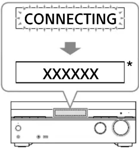
flowchart
graph TD
    A["CONNECTING"] --> B["XXXXXX *"]
    B --> C["Device"]
* "XXXXXX" represents the name of a detected BLUETOOTH device.
5 Press one of the input buttons to select the input you want.
The sound is output from the BLUETOOTH headphones/speakers. No sound is output from the receiver.
6 Adjust the volume of the BLUETOOTH headphones/speakers.
Volume control on the receiver and remote control only works for the BLUETOOTH headphones/speakers.
Note
- The BLUETOOTH device will be reconnected when [Bluetooth Mode] is changed from [Receiver] to [Transmitter]. Press BLUETOOTH TX/RX on the remote control to reconnect quickly.
- You can also press BLUETOOTH TX/RX on the remote control to switch [Bluetooth Mode]. However, you cannot switch [Bluetooth Mode] when "NOT. USE" appears on the display panel. Check if you are already using the Bluetooth function.
- When a headphone is connected to the PHONES jack, BLUETOOTH headphones/speakers cannot be connected.
What you can do with network features
You can enjoy playing back audio content in high-quality audio from a computer or network HDD, or iPhone/iPad/iPod touch or other smartphone or tablet connected to your home network either wired or wirelessly.
You can playback streaming music on the receiver by operating your smartphone with a streaming service-compatible app installed.
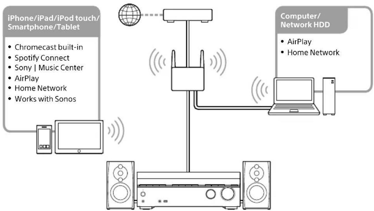
flowchart
graph TD
    A["iPhone/iPad/iPod touch/Smartphone/Tablet"] -->|Chromecast built-in<br>Spotify Connect<br>Sony | Music Center<br>AirPlay<br>Home Network<br>Works with Sonos| B["Computer/Network HDD"]
    A --> C["Device 1"]
    C --> D["Monitor"]
    D --> E["Reverter"]
    E --> F["Computer/Network HDD"]
    F --> G["Computer/Network HDD"]
    style A fill:#f9f,stroke:#333
    style B fill:#ccf,stroke:#333
    style C fill:#cfc,stroke:#333
    style D fill:#fcc,stroke:#333
    style E fill:#cff,stroke:#333
    style F fill:#ffc,stroke:#333
    style G fill:#fcc,stroke:#333
- Chromecast built-in™
You can select music on the Chromecast-enabled app and play it on the receiver. You can also play 360 Reality Audio content on the receiver.
- Spotify Connect
You can select music on the Spotify app and play it on the receiver.
Use your phone, tablet or computer as a remote control for Spotify. Go to spotify.com/connect to learn how.
- Sony | Music Center
You can control your receiver wirelessly using the "Sony | Music Center" app.
- AirPlay
This receiver supports AirPlay. You can enjoy audio content from an iPhone/iPad/iPod touch or your iTunes Library.
• Home Network (DLNA)
You can play content on the server device on your home network.
- Works with Sonos
You can play Sonos sound source/music content on the receiver using the Sonos app.
Additional Information
Saving power
You can save power by setting up the receiver as follows:
- Set [Standby Through] to [Off] in the [HDMI Settings] menu.
- Set [Network/Bluetooth Standby] in the [System Settings] menu to [Off].
- Set [Power] for [Zone2] or [Zone3] in the [Zone Controls] menu to [Off].
Note
If you agree to use the Chromecast built-in function, [Network/Bluetooth Standby] automatically switches to [On].
Reverting to the factory default settings
If the receiver still does not operate properly, reset the receiver as follows.
1 Press HOME.
The home menu is displayed on the TV screen.
2 Select [Setup] - [Resetting].
3 Select [All Settings].
4 Select [Start].
To cancel resetting
Select [Cancel] in step 4.
If you cannot perform resetting using the home menu
1 Press and hold ⏻ (power) on the receiver for more than 10 seconds.
The settings return to their initial status.
Note
- It takes a few minutes for the memory to be cleared completely. Do not turn the receiver off until "RESET" appears on the display panel.
- By resetting, the link with the wireless rear speakers/subwoofer (not supplied) may be lost. In this case, reconnect them by referring to their operating instructions.
Updating the Software
By updating your software to the latest version, you can take advantage of the newest functions.
The new software is available when:
- the "UPDATE" indicator lights up on the display panel.
- a message appears on the TV screen if the [Software Update Notification] is set to [On].
Note
Do not turn the receiver off or disconnect the AC power cord (mains lead) and the LAN cable until the download and update processes are completed. Doing so may cause a malfunction.
1 When you use Sony wireless rear speakers/subwoofer (not supplied), turn on each speaker and make sure the connection with the receiver is established.
The power indicator of the Sony wireless rear speakers/subwoofer (not supplied) lights up in green.
2 Press HOME.
The home menu is displayed on the TV screen.
3 Select [Setup] - [Software Update].
4 Select [Network Update] or [USB Update].
If you select [USB Update], please visit the following customer support website to download the latest software version.
https://www.sony.com/am/support
5 Check the software update progress.
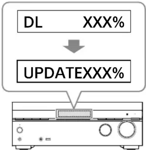
flowchart
graph TD
    A["DL"] -->|XXX%| B["UPDATEXXX%"]
The progress rate is displayed in percentage. The progress of loading software will be displayed as "DL XXX%" for the network update, and "RD XXX%" for the USB update.
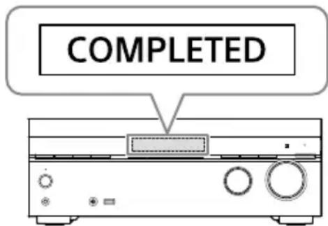
When the update is completed, "COMPLETED" appears on the display panel and the receiver restarts automatically.
Note
- It may take up to about 20 minutes for the update to be completed.
- You cannot restore the old version after updating the software.
- Set [Auto Update] to [On] when you want to perform software updates automatically. Depending on the contents of the updates, software update may be performed even if you set [Auto Update] to [Off]. For details, visit the Help Guide.
- If the update of Sony wireless rear speakers/subwoofer (not supplied) does not work, move them closer to the receiver and update them.
Troubleshooting
If the receiver does not work properly, handle it in the following order.
1 Search for the cause and solution of the issue by referring to these Operating Instructions or Help Guide.
The troubleshooting method is listed in "Troubleshooting."
For the functions that are not mentioned in Operating Instructions, refer to Help Guide.

https://rd1.sony.net/help/ha/ strtaan10/h_zz/


2 Search for the cause and solution of the issue on the Sony support site.
Sony support site provides latest support information and Frequently Asked Questions.
https://www.sony.com/am/support

3 Reset the receiver (page 53).
All the settings of the receiver return to their initial status.

4 Should any problems persist, consult your nearest Sony dealer.
General
The receiver is turned off automatically.
- If [Auto Standby] is set to [On], set it to [Off].
- "PROTECTOR" or "THERMAL" was activated (page 59).
The indicator on the display panel turns off.
- If the PURE DIRECT indicator on the front panel lights up, press PURE DIRECT to turn off this function.
- Press DIMMER on the receiver to adjust the brightness of the display panel.
Video
No image appears on the TV screen.
- Try pressing the input button on the remote control or turning INPUT SELECTOR on the receiver to select the input to which you want to watch.
- Set your TV to the appropriate input mode.
- Make sure that cables are correctly and securely connected to devices.
- Disconnect the HDMI cable from the receiver and TV and then reconnect the cable.
- Change the [HDMI Signal Format] setting of the selected input in the [HDMI Settings] menu. For details, visit the Help Guide.
-
Some playback devices need to be set up. Refer to the operating instructions supplied with each device.
-
Be sure to use a Premium High Speed HDMI Cable with Ethernet, which supports bandwidths up to 18 Gbps. For video signals that require a high bandwidth such as 4K/120p, 8K, etc., be sure to use an Ultra High Speed HDMI Cable that supports bandwidths up to 48 Gbps.
- The output of the HDMI video signals of the receiver may be set to "HDMI OFF". In this case, set to "HDMI A", "HDMI B", or "HDMI A+B" by pressing HDMI OUT on the remote control.
- If you want to play HDCP 2.2 or HDCP 2.3 content, connect the receiver to an HDMI input jack of a TV that is compatible with HDCP 2.2 or HDCP 2.3.
4K or 8K content cannot be displayed at the same resolution as the source.
- Depending on the TV or the video device, 4K or 8K content may not be displayed. Check the video capability and settings of your TV and video device.
- Be sure to use a Premium High Speed HDMI Cable with Ethernet, which supports bandwidths up to 18 Gbps. For video signals that require a high bandwidth such as 4K/120p, 8K, etc., be sure to use an Ultra High Speed HDMI Cable that supports bandwidths up to 48 Gbps.
- If your TV have similar menu for high bandwidth video format, check the setting on the TV menu. For details on the TV menu setting, refer to the operating instructions of the TV.
- Be sure to connect the receiver to an HDMI input jack of a TV or video device that is supporting 4K or 8K. You have to connect an HDMI cable to an HDMI jack that supports HDCP 2.2 or HDCP 2.3 when you use a playback device for 4K or 8K resolution video content, etc.
- Disconnect the HDMI cable from the receiver and TV and then reconnect the cable.
- Supported video signals vary depending on the HDMI IN jack. For details on the supported video signals, see "Video signals supported by HDMI jacks" (page 34).
The home menu does not appear on the TV screen.
- The home menu can only be used when you connect the TV to the HDMI OUT jack on the receiver.
- When you connect the TV to HDMI OUT B/ZONE 2 jack, be sure to set [HDMI OUT B Mode] to [Main] in the [HDMI Settings] menu. Press HDMI OUT repeatedly on the remote control to select "HDMI B" or "HDMI A+B."
- Press HOME to display the home menu.
- Check that the TV is connected correctly.
- Disconnect the HDMI cable from the receiver and TV and then reconnect the cable.
- The home menu may take some time to appear on the TV screen depending on the TV.
HDR (High Dynamic Range) images cannot be displayed in HDR mode.
- Depending on the TV or video equipment, HDR images may not be displayed in HDR mode. Check the video capability and setting of your TV or video equipment.
- Depending on the receiver setting, some video equipment may not output HDR content in HDR mode due to lack of signal bandwidth, even if both TV and video equipment support HDR. In this case, set [HDMI Signal Format] of the selected input to [Enhanced format] or [Enhanced format (4K120, 8K)] in the [HDMI Settings] menu.
Audio
No sound or only a very low level of sound is heard, no matter which device is selected.
- Check that all connecting cables are inserted to their input/output jacks on the receiver, speakers and the devices.
- Check that the receiver and all devices are turned on.
- Check that MASTER VOLUME on the receiver is not set to "VOL MIN."
- Press SPEAKERS on the receiver to select a setting other than "SPK OFF" (page 43).
- Check that headphones are not connected to the receiver.
-
Press ☑ (muting) to cancel the muting function.
-
Try pressing the input button on the remote control or turning INPUT SELECTOR on the receiver to select the input to which you want to watch.
- When [Control for HDMI] is set to [On] or [Audio Return Channel] is set to either [eARC] or [ARC] in the [HDMI Settings] menu:
- Check that the speaker output setting on the TV is set to "Audio System." If you want to listen to sound from the TV speaker, set it to "TV Speaker."
When [Control for HDMI] is set to [Off] and [Audio Return Channel] is set to [Off] in the [HDMI Settings] menu:
- If you want to listen to sound from the TV speaker, set [Audio Out] to [TV + AMP] in the [HDMI Settings] menu. If you cannot play multi-channel audio source, set [AMP]. However, the sound will not be output through the TV speaker.
- Set [Bluetooth Mode] to other than [Transmitter].
- Set [DSD Native] in [Audio Settings] to [Off]. If the speaker assigned as a signal source is not installed, playback is not available during DSD Native playback because content will be played on the target speaker. Also, Zone output is not available because downmix process does not work.
Cannot select the desired input for playback in Zone 2 or Zone 3.
- There are limits to the inputs that can be played in Zone 2 and Zone 3. For details, see "Selectable input and functional restriction in Zone 2 and Zone 3" (page 46).
No sound is heard from the subwoofer or the center speaker.
- Sound may not be output from the target speakers depending on the playback signals or the speaker settings.
- Be sure to select the optimal sound field for the content. For details on relations between sound fields and speaker outputs, see page 48.
No sound is heard from the wireless speaker (not supplied).
- During DVD-Audio or SA-CD playback, no sound will be output from wireless speakers because of copyright protection restrictions. Switch the speaker configuration to wired connection.
Sound heard from the wireless speaker (not supplied) is unstable.
- Do not place metal objects other than a TV near the receiver. The wireless function with the wireless speaker (not supplied) will be affected and the sound will become unstable.
- Do not put the receiver in a metal rack. The wireless function with the wireless speaker (not supplied) will be affected and the sound will become unstable.
The sound is interrupted.
- Sound may be interrupted when the sampling frequency, number of channels or audio format of audio output signals from the playback device is switched.
When a TV is connected to the receiver via an HDMI OUT A (TV) jack that supports the eARC or ARC function, sound from the TV is not output from the speakers connected to the receiver.
- Set [Audio Return Channel] to [eARC] or [ARC] in the [HDMI Settings] menu.
- Make sure that your TV is compatible with the eARC or ARC function.
- Make sure that the HDMI cable is connected to a jack on your TV that is compatible with the eARC or ARC function.
- If you connect to a TV that is compatible with the ARC function but not compatible with the eARC function, set [Audio Return Channel] to [ARC] in the [HDMI Settings] menu.
- If you connect to a TV that is incompatible with both the eARC and ARC functions, set [Audio Return Channel] to [Off] in the [HDMI Settings] menu, and connect the TV to the OPTICAL IN TV jack of this receiver with an optical cable.
There is a time gap between the visual display on the TV and the audio output from the speaker connected to the receiver.
- Change the [A/V Sync] settings in the [Audio Settings] menu.
- Adjust the A/V Sync settings on the TV. For details, refer to the operating instructions of the TV.
- When the sound field is set to [Audio Enhancer], change the sound field to other than [Audio Enhancer]. For details on the sound fields, see "Selectable sound fields and their effects" (page 50).
The surround effect cannot be obtained.
- Be sure to select the optimal sound field for the content. For details on the sound fields, see "Selectable sound fields and their effects" (page 50).
- To activate the virtualizer and obtain the surround effect when the speaker pattern is set to [2.0] or [2.1], set [Sound Field] to [A.F.D.], [A.F.D. Movie], [Dolby Mode] or [DTS:X Mode], set [Upmixer] to [Auto], and set [Virtualizer] to other than [Off].
Volume level of Zone 2 speakers cannot be adjusted.
- You can only select an input from the HDMI IN jacks in Zone 2. Since the audio signals are output from the HDMI OUT B/ZONE 2 jack as they are, you cannot adjust the volume level on the receiver. Adjust the volume on the device connected to the HDMI OUT B/ZONE 2 jack.
The center component of the audio is not output from the TV when using the TV as a center speaker by connecting the S-CENTER OUT jack of the receiver to the S-CENTER SPEAKER IN jack of the TV. (The Acoustic Center Sync function is not working)
- Check that [Control for HDMI] is [On] in the [HDMI Settings] menu.
- Press HOME, select [Setup]
- [Speaker Settings] - [TV/Screen Center Settings] - [TV Center Speaker Mode] and then set to [On].
- Select a sound field other than [2ch Stereo].
- The sound may not be output through the TV speaker depending on the sound source.
- When a BLUETOOTH device is connected and [Bluetooth Mode] is set to [Transmitter], or a headphone is connected, the sound will not be output through the TV speaker.
Network connection
Cannot connect to the network.
- Check that the LAN cable is connected to the receiver when you want to connect the receiver to the network via a wired LAN connection.
- Check the network information. If the connection failed, set up the network connection again.
-
If the receiver is connected through a wireless network, move the receiver and the wireless LAN router/access point closer to each other and perform the setup again.
-
Make sure that you use a wireless LAN router/access point.
- Make sure that the wireless LAN router/access point is turned on.
- Check the settings of the wireless LAN router/access point and perform the setup again. For details on the settings of devices, refer to the operating instructions of the devices.
- Wireless networks are influenced by electromagnetic radiation emitted by microwave ovens and other devices. Move the receiver away from these devices.
Error messages
"PROTECTOR" or "THERMAL" appears on the display panel.
The receiver will automatically turn off after a few seconds. Check the followings:
- There may be an electrical surge or power failure. Unplug the AC power cord (mains lead) and then plug in the cord again after 30 minutes.
- The receiver is covered and the ventilation holes are blocked. Remove the object covering the ventilation holes of the receiver.
- The impedance of the connected speakers is below the rated impedance range indicated on the back panel of the receiver. Reduce the volume level.
-
Unplug the AC power cord (mains lead) and let the receiver cool down for 30 minutes while performing the following troubleshooting:
-
Disconnect all of the speakers and subwoofer.
- Check that the speaker wires are tightly twisted on both ends.
- Connect the front speaker first, increase the volume level and operate the receiver for at least 30 minutes until it completely warms up. Then, connect each additional speaker one by one and test each additional speaker until you detect which speaker is causing the protection error.
After checking the above items and fixing any problems, plug in the AC power cord (mains lead) and turn on the receiver. If the problem persists, consult your nearest Sony dealer.
[Overload has been detected.] appears on the TV screen.
An over-current from the (USB) port was detected. Disconnect the USB device as prompted in the warning message and close the message.
List of messages after Auto Calibration measurements
Error 30
Headphones inserted. Remove headphones and re-measure.
Error 31
SPEAKERS(A/B/A+B/OFF) are off. Re-measure with audio coming out of the SPEAKERS (A/B/A+B/OFF). For details on selecting the front speakers, see "Selecting the front speakers" (page 43).
Error 32
No sound was detected from any channel. Is the measurement microphone damaged? Is it connected to the CALIBRATION MIC jack on the front of this unit?
Error 34
Front speakers are not installed in the correct position. Left/right of the microphone and speakers may be installed in reverse.
* The speaker name in this error message depends on the detected symptom.
Error 35
Center speaker pattern settings and measurement results do not match. Check the center speaker pattern and connection.
* The speaker name in this error message depends on the detected symptom.
Error 36
3D position could not be measured.
Microphone or microphone stand may be misaligned. Return to the correct position and try again. If noisy, measure with as little surrounding noise as possible.
Error 37
- No sound was detected from either the left or right surround speakers. Is the power for the wireless speakers that are used as the surround speakers turned on?
- No sound was detected from either the left or right surround back speakers. Is the power for the wireless speakers that are used as the surr. back speakers turned on?
- To output audio from the connected wireless speakers, update software to the latest version. Press [HOME] on the remote for this unit and select "Setup" to update.
Error 38
It wasn't possible to measure correctly. Move the speaker or microphone position a little and try again. If noisy, measure with as little surrounding noise as possible.
Warning 40
Measurement complete, but it is noisy. It may be possible to measure again, but it is not possible to measure in all environments. Measure with as little surrounding noise as possible.
Warning 41, Warning 42
The input from the measurement microphone is excessive. The speaker and microphone may be too close. Place the speaker and microphone away from each other. If using this unit as a preamplifier, this message may be displayed depending on the connected power amplifier, but it can be used as it is.
Warning 43
The subwoofer distance and phase could not be measured. Noise may be the cause. Re-measure in a quiet surrounding environment.
Warning 44
Measurement finished, but the center speaker positional relationship may be unsuitable. Check the speaker position referring to "Installing speakers" in the Help Guide.
* The speaker name in this warning message depends on the detected symptom.
Precautions
On safety
Should any solid object or liquid fall into the cabinet, unplug the receiver and have it checked by qualified personnel before operating it any further.
On power sources
- Before operating the receiver, check that the operating voltage is identical with your local power supply.
The operating voltage is indicated on the nameplate on the back of the receiver.
- If you are not going to use the receiver for a long time, be sure to disconnect the receiver from the wall outlet. To disconnect the AC power cord (mains lead), grasp the plug itself; never pull the cord.
- The AC power cord (mains lead) must be changed only at a qualified service shop.
- To reduce the risk of electric shock, the speaker cable should be connected to the apparatus and the speakers in accordance with the following instructions.
1) Disconnect the AC power cord from the MAINS.
2) Strip 10 to 15 mm of the wire insulation of the speaker cable.
3) Connect the speaker cable to the apparatus and the speakers carefully so as not to touch the core of speaker cable by hand. Also disconnect the AC power cord from the MAINS before disconnecting the speaker cable from the apparatus and the speakers.
On heat buildup
Although the receiver heats up during operation, this is not a malfunction. If you continuously use this receiver at a large volume, the cabinet temperature of the top, side and bottom rises considerably*. To avoid burning yourself, do not touch the cabinet.
On placement
- Do not install the appliance in a confined space, such as a bookcase.
- Place the receiver in a location with adequate ventilation to prevent heat buildup and prolong the life of the receiver.
- Do not place the receiver near heat sources, or in a place subject to direct sunlight, excessive dust, or mechanical shock.
- Do not place anything on top of the cabinet that might block the ventilation holes and cause malfunctions.
On operation
Before connecting other device, be sure to turn off and unplug the receiver.
On cleaning
Clean the cabinet, panel, and controls with a soft cloth slightly moistened with a mild detergent solution. Do not use any type of abrasive pad, scouring powder, or solvent, such as alcohol or benzine.
On updating
This receiver allows you to update the software automatically when connected to the Internet via a wired or wireless network. You can add new features and use the receiver with more convenience and safety by updating the receiver.
If you do not want to update automatically, set [Auto Update] to [Off].
However, the receiver may update the software automatically for reasons such as safety, even if this function is disabled.
You can also update the software using the settings menu when this function is disabled.
For details on the setting, see "Updating the Software" (page 54).
You may not use the receiver while the software is being updated.
On Internet connection
When connecting the receiver to the Internet, use the router (ADSL modem or optical line termination device with the router function supplied with the Internet provider, or Wi-Fi access point). If you connect to the Internet without using the router, a security problem may occur. If you are not sure that the wall outlet for the network line has the router function, ask your manager of the apartment house or Internet provider.
On BLUETOOTH communication
Supported BLUETOOTH version and profiles
Profile refers to a standard set of functions for various BLUETOOTH product features. See "BLUETOOTH section" in "Specifications" (page 65) for the BLUETOOTH version and profiles supported by this receiver.
Effective communication range
BLUETOOTH devices should be used within approximately 30 meters (98.4 feet) (unobstructed distance) of each other. The effective communication range may become shorter under the following conditions.
- When a person, metal object, wall or other obstruction is between the devices with a BLUETOOTH connection
- Locations where a wireless LAN is installed
- Around microwave ovens that are in use
- Locations where other electromagnetic waves are generated
Effects of other devices
BLUETOOTH devices and wireless LAN (IEEE 802.11b/g/n) device use the same frequency band (2.4 GHz). When using your BLUETOOTH device near a device with wireless LAN capability, electromagnetic interference may occur. This could result in lower data transfer rates, noise, or inability to connect. If this happens, try the following remedies:
- Use this receiver at least 10 meters (33 feet) away from the wireless LAN device.
- Turn off the power to the wireless LAN device when using your BLUETOOTH device within 10 meters (33 feet).
- Install this receiver and BLUETOOTH device as closer to each other as possible.
Effects on other devices
The radio waves broadcast by this receiver may interfere with the operation of some medical devices. Since this interference may result in malfunction, always turn off the power on this receiver and BLUETOOTH device in the following locations:
- In hospitals, on trains, in airplanes, at gas stations, and any place where flammable gasses may be present
- Near automatic doors or fire alarms
Note
- This receiver supports security functions that comply with the BLUETOOTH specification to ensure secure connection during communication using BLUETOOTH technology. However, this security may be insufficient depending on the setting contents and other factors, so always be careful when performing communication using BLUETOOTH technology.
- Sony shall not be held liable in any way for damages or other loss resulting from information leaks during communication using BLUETOOTH technology.
- BLUETOOTH communication is not necessarily guaranteed with all BLUETOOTH devices that have the same profile as this receiver.
- BLUETOOTH devices connected with this receiver must comply with the BLUETOOTH specification prescribed by the Bluetooth SIG, Inc., and must be certified to comply. However, even when a device complies with the BLUETOOTH specification, there may be cases where the characteristics or specifications of the BLUETOOTH device make it impossible to connect, or may result in different control methods, display or operation.
- Noise may occur or the audio may cut off depending on the BLUETOOTH device connected with this receiver, the communications environment, or surrounding conditions.
If you have any questions or problems concerning your receiver, please consult your nearest Sony dealer.
Licenses
- Dolby, Dolby Vision, Dolby Atmos, Dolby Audio, and the double-D symbol are trademarks of Dolby Laboratories Licensing Corporation. Manufactured under license from Dolby Laboratories. Confidential unpublished works. Copyright © 1992 -2021 Dolby Laboratories. All rights reserved.
- Manufactured under license from IMAX Corporation. IMAX® is a registered trademark of IMAX Corporation in the United States and/or other countries. For DTS patents, see http://patents.dts.com. Manufactured under license from DTS, Inc. DTS, DTS:X, Virtual:X, and the DTS:X logo are registered trademarks or trademarks of DTS, Inc. in the United States and other countries. © 2022 DTS, Inc. ALL RIGHTS RESERVED.
- Use of the Works with Apple badge means that an accessory has been designed to work specifically with the technology identified in the badge and has been certified by the developer to meet Apple performance standards.
- This product is protected by certain intellectual property rights of Microsoft Corporation. Use or distribution of such technology outside of this product is prohibited without a license from Microsoft or an authorized Microsoft subsidiary.
- For details of the GPL, LGPL and other software licenses, please refer to [Setup]–[System Settings]–[Software License Information] on the product.
- The software included in this product contains copyrighted software that is licensed under the GPL/LGPL and other licenses which may require access to source code. You may find a copy of the relevant source code as required under the GPL/LGPL (and other licenses) at the following URL.
You may obtain the source code as required by the GPL/LGPL on a physical medium from us for a period of three years after our last shipment of this product by applying through the form at the following URL.
This offer is valid to anyone in receipt of this information.
https://oss.sony.net/Products/Linux/ Please note that Sony cannot answer or respond to any inquiries regarding the content of this source code.
- The Spotify Software is subject to third party licenses found here:
https://www.spotify.com/connect/third-party-licenses.
- Disclaimer regarding services offered by third parties
Network services, content and the (operating system and) software of this product may be subject to individual terms and conditions and changed, interrupted or discontinued at any time and may require fees, registration and credit card information.
Trademarks
- Windows Media is either a registered trademark or trademark of Microsoft Corporation in the United States and/or other countries.
- The LDAC™ name is a trademark of Sony Group Corporation or its affiliates.
- LDAC is an audio coding technology developed by Sony that enables the transmission of High-Resolution (Hi-Res) Audio content, even over a Bluetooth connection. Unlike other Bluetooth compatible coding technologies such as SBC, it operates without any down-conversion of the Hi-Res Audio content*, and allows approximately three times more data** than those other technologies to be transmitted over a Bluetooth wireless network with unprecedented sound quality, by means of efficient coding and optimized packetization.
* excluding DSD format contents
** in comparison with SBC (Subband Coding) when the bitrate of 990 kbps (96/48 kHz) or 909 kbps (88.2/44.1 kHz) is selected
- The Bluetooth® word mark and logos are registered trademarks owned by Bluetooth SIG, Inc. and any use of such marks by Sony Group Corporation and its subsidiaries is under license.
- The terms HDMI™, HDMI High-Definition Multimedia Interface, and the HDMI Logo are trademarks or registered trademarks of HDMI Licensing Administrator, Inc.
- Google, Google Play, Google Home and Chromecast built-in are trademarks of Google LLC. Google Assistant is not available in certain languages and countries.
- Apple, AirPlay, iPad, iPhone and iPod touch are trademarks of Apple Inc., registered in the U.S. and other countries.
- "BRAVIA" logo is a trademark of Sony Group Corporation or its affiliates.
- Wi-Fi®, Wi-Fi Protected Access® and Wi-Fi Alliance® are registered trademarks of Wi-Fi Alliance.
- Wi-Fi CERTIFIED™, WPA™, and WPA2™ are trademarks of Wi-Fi Alliance.
- Being Roon Tested means that Sony and Roon have collaborated to ensure you have the best experience using Roon software and Sony equipment together, so you can just enjoy the music.
- "TRILUMINOS" and "TRILUMINOS" logo are a registered trademark of Sony Group Corporation or its affiliates.
- Spotify and Spotify logos are trademarks of the Spotify Group.*
* Depending on the country and region, this function may not be available.
- All other trademarks and registered trademarks are trademarks or registered trademarks of their respective holders. In this manual, ^TM and ^® marks are not specified.
Specifications
AUDIO POWER SPECIFICATIONS
POWER OUTPUT AND TOTAL HARMONIC DISTORTION (USA Models Only):
With 6 ohm loads, both channels driven, from 20 Hz – 20 000 Hz; rated 100 watts per channel minimum RMS power in stereo mode, with no more than 0.09% total harmonic distortion from 250 milliwatts to rated output.
Amplifier section ^1)
Minimum RMS Output Power
(6 ohms, 20 Hz – 20 kHz, THD 0.09%) 100 W + 100 W
Stereo Mode Output Power
(6 ohms, 1 kHz, THD 0.9%) 120 W + 120 W
Surround Mode Output Power ^2)
(6 ohms, 1 kHz, THD 0.9%) 165 W per channel
^1) Measured under the following conditions: Power requirements 120 V AC, 60 Hz
2) Reference power output for front, center, surround and surround back speakers. Depending on the sound field settings and the source, there may be no sound output.
Frequency response Analog
10 Hz – 100 kHz, +0.5/-2 dB (with sound field, equalizer and 360SSM bypassed)
Input
Analog Sensitivity: 500 mV/50 kilohms S/N ^3) : 105 dB (A, 500 mV ^4) )
Digital (Coaxial) Impedance: 75 ohms S/N: 100 dB (A, 20 kHz LPF)
Digital (Optical) S/N: 100 dB (A, 20 kHz LPF)
Output (Analog) ZONE 3
Voltage: 2 V/1 kilohm
SUBWOOFER Voltage: 2 V/1 kilohm
Equalizer
Gain levels ±10 dB, 1 dB step
3) INPUT SHORT (with sound field and equalizer bypassed).
^4) Weighted network, input level.
FM tuner section
Tuning range
87.5 MHz - 108.0 MHz (100 kHz step)
Antenna (aerial)
FM wire antenna (aerial)
Antenna (aerial) terminals 75 ohms, unbalanced
Video section
Inputs/Outputs
Video: 1 Vp-p, 75 ohms
HDMI Video
Resolution
- 480p/60 Hz
- 576p/50 Hz
• 720p/60 Hz, 50 Hz, 30 Hz, 24 Hz
• 1080i/60 Hz, 50 Hz - 1080p/120 Hz, 100 Hz, 60 Hz, 50 Hz, 30 Hz, 24 Hz
- 4K/120 Hz*, 100 Hz*, 60 Hz, 50 Hz, 30 Hz, 25 Hz, 24 Hz
- 8K/60 Hz*, 50 Hz*, 30 Hz*, 25 Hz*, 24 Hz*
* GAME (for AUDIO) and MEDIA BOX jacks support
Support
HDCP2.3, HDR (HDR10, Hybrid Log-Gamma, Dolby Vision), 3D, Deep Color, ITU-R BT.2020, eARC/ARC, VRR, ALLM For details on supported video formats, visit the Help Guide.
USB section
Ψ (USB) port:
Type A (For connecting USB flash drive)
Maximum current
1A
Network section
Ethernet LAN
100BASE-TX
Wireless LAN
Compatible standards: IEEE 802.11 a/b/g/n/ac
Security: WPA/WPA2-PSK
Radio frequency: 2.4 GHz, 5 GHz
BLUETOOTH section
Communication system
BLUETOOTH Specification version 5.0
Output
BLUETOOTH Specification Power Class 1
Maximum communication range
Line of sight approx. 30 m (98.4 feet) ^1)
Maximum number of devices to be registered 10 devices
Frequency band
2.4 GHz band (2.4000 GHz - 2.4835 GHz)
Modulation method
FHSS (Freq Hopping Spread Spectrum)
Compatible BLUETOOTH profiles ^2)
A2DP (Advanced Audio Distribution Profile) AVRCP (Audio Video Remote Control Profile)
Supported Codecs ^3)
SBC ^4) , AAC, LDAC
Transmission range (A2DP)
20 Hz – 40 000 Hz (LDAC sampling frequency 96 kHz with 990 kbps transmission) 20 Hz – 20 000 Hz (Sampling frequency 44.1 kHz)
1) The actual range will vary depending on factors such as obstacles between devices, magnetic fields around a microwave oven, static electricity, cordless phone, reception sensitivity, antenna's performance, operating system, software application, etc.
2) BLUETOOTH standard profiles indicate the purpose of BLUETOOTH communication between devices.
3) Codec: Audio signal compression and conversion format
4) Subband Codec
Wireless Transmitter/Receiver Section
Communication system
Wireless Sound Specification version 4.0
Frequency band
5 GHz
Modulation method
OFDM
General
Power requirements
120 V AC, 60 Hz
Power consumption 240 W
Standby mode: 0.5 W
(When [Standby Through],
[Network/Bluetooth Standby], and all zone power are set to [Off].)
Network/Bluetooth Standby mode: 3.5 W
(When [Network/Bluetooth Standby] is set to [On], and [Standby Through], and all zone power are set to [Off].)
Dimensions (width/height/depth) (Approx.)
430 mm × 156 mm × 331 mm (17 in ×
6^1/4 in × 13^1/8 in) including projecting parts and controls
Mass (Approx.)
9.4 kg (20 lb 12 oz)
Design and specifications are subject to change without notice.
playable types of audio files
| Codec Extension | |
| MP3 (MPEG-1 Audio Layer III) .mp3 | |
| MPEG-H .mp4 | |
| AAC/HE-AAC ^1) | .m4a, .aac ^2) , .mp4 ^2) , .3gp ^2) |
| WMA9 Standard ^1) | .wma |
| LPCM .wav | |
| FLAC ^1) | .flac |
| DSF ^1) | .dsf |
| DSDIFF ^1), 3) | .dff |
| AIFF ^1) | .aiff, .aif |
| ALAC ^1) | .m4a |
| Vorbis .ogg | |
| Monkey's Audio .ape |
1) The receiver may not play this file format on a home network server.
2) The receiver does not play this file format on a home network server.
3) The receiver does not play DST encoded files.
Note
- Some files may not play depending on the file format, the file encoding, the recording condition, or the home network server condition.
- Some files edited on a PC may not play.
- Fast forward or fast reverse may not be available with some files.
- The receiver does not play coded files such as DRM.
- Some USB devices may not work with this receiver.
- The receiver can recognize Mass Storage Class (MSC) devices.
Supported digital audio formats
The digital audio formats that this receiver can decode depend on the digital audio output jacks of the connected device. This receiver supports the following audio formats. The words in brackets are those indicated on the display panel.
| Digital audio format Maximum number of decoding/rendering channels | Connection with the receiver |
| Dolby Digital [DD] 5.1 COAXIAL/OPTICAL, HDMI, | eARC, ARC |
| Dolby Digital Plus [DD+]1) | 7.1 HDMI, eARC, ARC |
| Dolby Atmos - Dolby Digital Plus [ATMOS]1),2) | HDMI, eARC, ARC |
| DTS [DTS] 5.1 COAXIAL/OPTICAL, HDMI, | eARC, ARC |
| DTS 96/24 [DTS] 5.1 COAXIAL/OPTICAL, HDMI, | eARC, ARC |
| LPCM [LPCM] 7.1/2.0 COAXIAL/OPTICAL(2.0), | HDMI(7.1), eARC(7.1), ARC(2.0) |
| Dolby TrueHD [DTHD]1) | 7.1 HDMI, eARC |
| Dolby Atmos TrueHD [ATMOS]1),2) | HDMI, eARC |
| Dolby Atmos [ATMOS] 5.1.2, 7.1, or 7.1.23) | HDMI, eARC |
| DTS-ES DISCRETE (DTS-ES Discrete 6.1) [DTS] | 6.1 COAXIAL/OPTICAL, HDMI, eARC, ARC |
| DTS-ES MATRIX(DTS-ES Matrix 6.1) [DTS] | 6.1 COAXIAL/OPTICAL, HDMI, eARC, ARC |
| DTS-HD High Resolution Audio [DTS-HD]1) | 7.1 HDMI, eARC |
| DTS-HD Master Audio [DTS-HD]1) | 7.1 HDMI, eARC |
| DTS Express [DTS-HD] 5.1 HDMI, eARC | |
| DTS:X Master Audio [DTS:X]1) | 5.1.2, 7.1, or 7.1.2) |
| DTS:X [DTS:X]1) | 5.1.2, 7.1, or 7.1.2) |
| DSD [DSD]4),5) | 5.1 HDMI |
^1) Audio signals are output in another format if the playback device does not correspond to the actual format. For details, refer to the operating instructions of the playback device.
2) Dolby Atmos is decoded as Dolby Digital Plus or Dolby TrueHD if the speaker pattern is set to 2.0, 2.1, 3.0, 3.1, 4.0, 4.1, 5.0 or 5.1 and [Virtualizer] is set to [Off].
3) Available only when [SpeakerRelocation/PhantomSurroundBack] is set to [Type A] or [Type B].
4) This format is not output to wireless headphones.
5) This format is not output to wireless speakers.
Consultez : https://www.sony.com/electronics/support
Service Center 12451 Gateway Blvd., Fort Myers, FL 33913
natural_image
Line drawing of a handheld cable with a connector (no text or symbols)natural_image
Diagram showing a device being processed from a left-side component to an external casing (no text or symbols present)Remarque
11 Prises IR REMOTE IN/OUT
1 Touches ⏻ (alimentation) (MAIN, ZONE 2, ZONE 3)
MAIN, ZONE 2, ZONE 3
GAME, MEDIA BOX, BD/DVD, SAT/CATV, VIDEO, AUX, TV, SA-CD/CD, OTHERS
▶II (lecture/pause) ^2)
Saut, lecture, pause.
PRESET +/-
flowchart
graph TD
    TML --> FHL
    TML --> FDR
    TML --> FHR
    FHL --> FL
    FDR --> FR
    FHR --> CNT
    SW --> SDL
    SDL --> SL
    SBL --> SBR
    SBR --> SDR
    SBR --> SR
    CNT --> ICLR
    ICLR --> CNT
    ICLR --> FR
    ICLR --> FDR
    ICLR --> FHR
    ICLR --> FHL
    ICLR --> FHL
    ICLR --> FHL
    ICLR --> FHL
    ICLR --> FHL
    ICLR --> FHL
    ICLR --> FHL
    ICLR --> FHL
Astuce

natural_image
Diagram of a cable connector with a rotating arrow indicating rotation (no text or symbols)Remarque
natural_image
Pure electrical circuit lines without any symbolsEnceintes surround Enceinte centrale
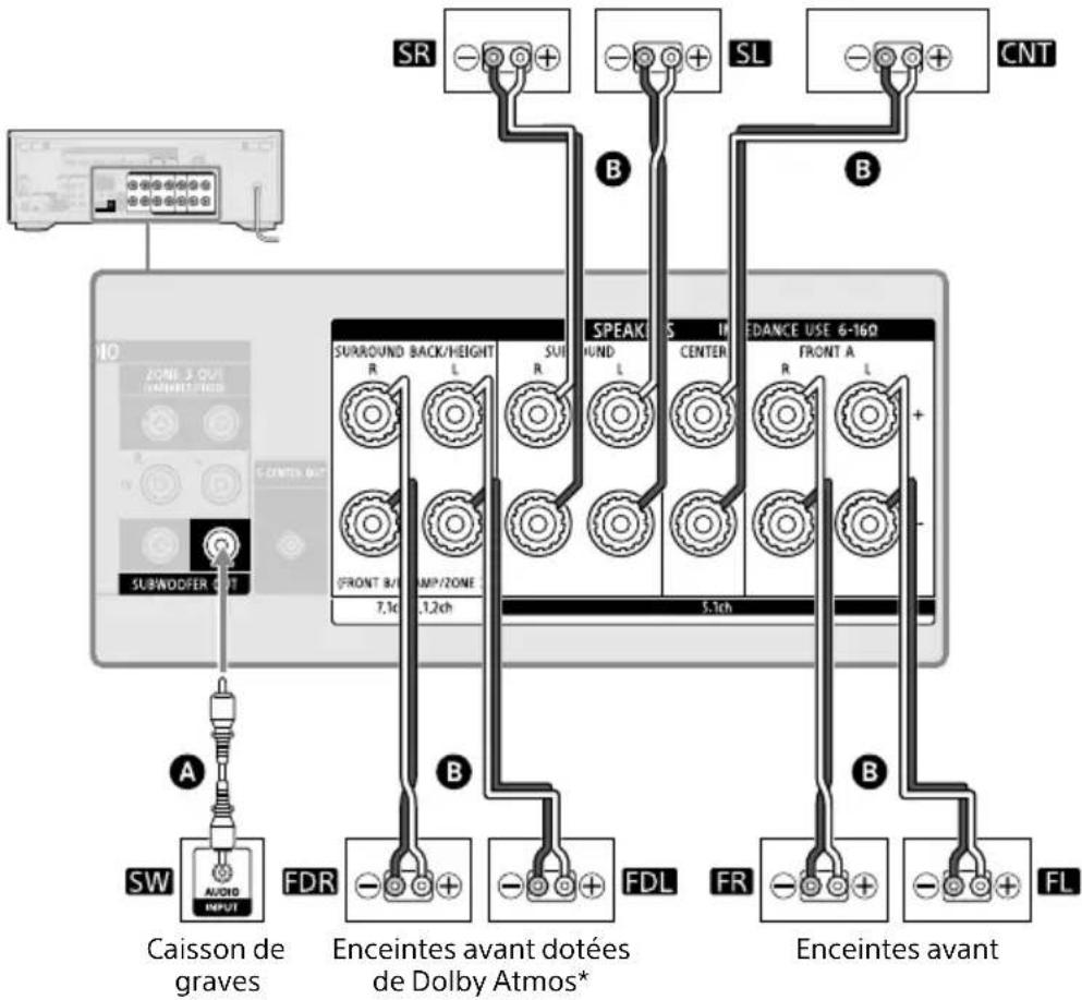
flowchart
graph TD
    A["Caisson de graves"] --> B["SW"]
    B --> C["OUTPUT"]
    D["SubWODDER OUT"] --> E["Switch"]
    F["RS"] --> G["+"]
    H["SL"] --> I["+"]
    J["CNT"] --> K["+"]
    L["SURROUND BACK/HEIGHT R"] --> M["L"]
    N["SUI R"] --> O["L"]
    P["SPEAK ROUND"] --> Q["S"]
    R["SPEAK L"] --> S["S"]
    T["SPEAK CENTER"] --> U["S"]
    V["SPEAK FL"] --> W["FDR"]
    X["SPEAK FR"] --> Y["FDL"]
    Z["SPEAK FL"] --> AA["FL"]
    AB["FR"] --> AC["+"]
    AD["ENCEINTES avant dotées de Dolby Atmos*"] --> AE["7,1c"]
    AF["5,1ch"] --> AG["1,2ch"]
    AH["ENDANCE USE 6-160 FRONT A"] --> AI["R"]
    AJ["ENDANCE USE 6-160 FRONT A"] --> AK["L"]
natural_image
Simple line drawing of a room with two labeled items (L and R) and a central object, no text or symbols present.① 30^
② 100^-120^
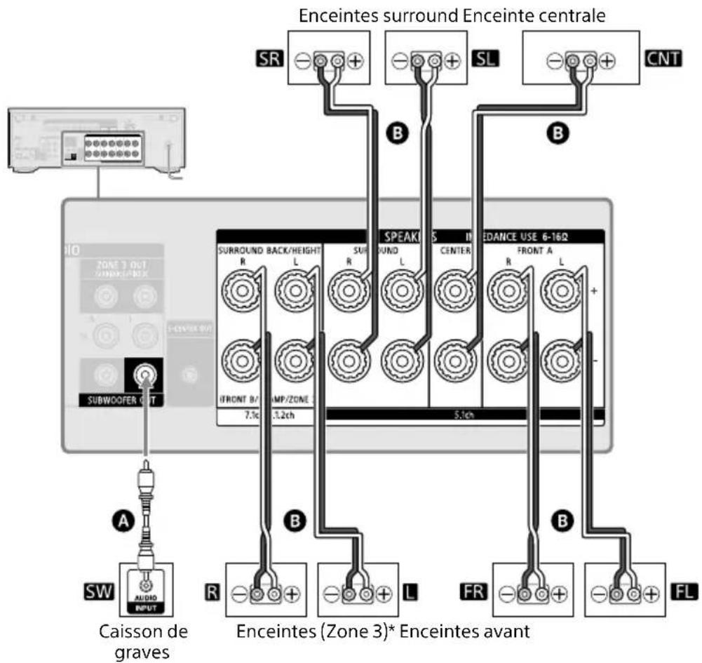
Enceintes surround Enceinte centrale
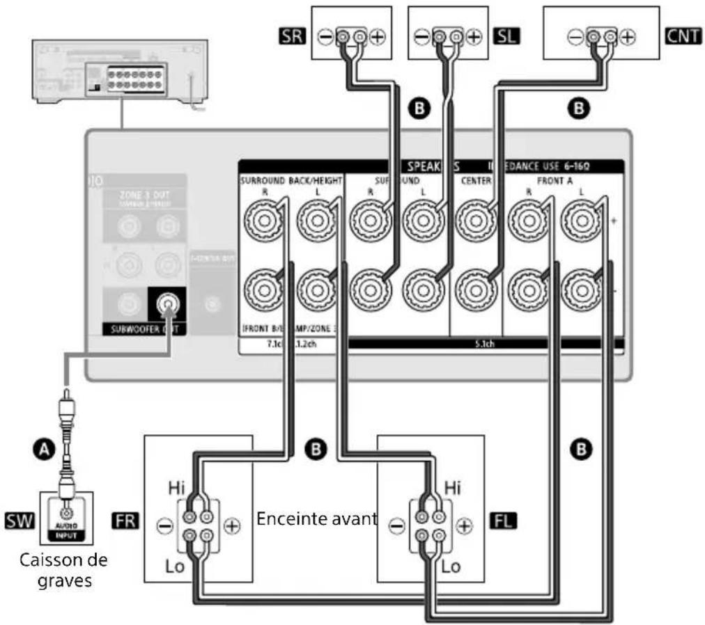
A Câble audio (non fourni)
Remarque
flowchart
graph TD
    A["HELLO"] --> B["PLEASEWAIT"]
    B --> C["Device"]
natural_image
Line drawing of a portable electronic device with indicator lights and ports (no text or symbols)Remarque
natural_image
Two identical mechanical device setups with a cable and base, labeled ① and ② (no text or symbols on the devices themselves)Remarque
- Chromecast built-in™
- Sony | Music Center
https://www.sony.com/am/support
https://www.sony.com/am/support

Plage de communication effective
Visite: https://www.sony.com/electronics/support
Contacto: Sony Customer Information Service
Parte responsible: Sony Electronics Inc.
natural_image
Line drawing of a cable with a connector and cable strap (no text or symbols)natural_image
Diagram showing a device component being processed from a left-side view, with no visible text or symbols.Nota
MAIN, ZONE 2, ZONE 3
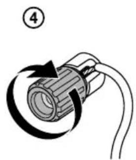
natural_image
Diagram of a cylindrical connector with a curved arrow indicating rotation or movement (no text or symbols)Nota
natural_image
Pure electrical circuit lines without any symbolsnatural_image
Simple line drawing of a room with two labeled items (L and R) and a central object, no text or symbols present.① 30^
② 100^-120^
Altavoces envolventes Altavoz central
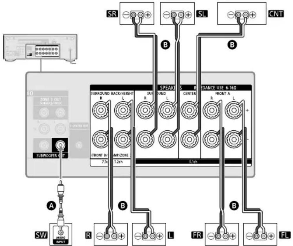
Altavoz
potenciador
de graves
Altavoces (Zona 3)* Altavoces delanteros
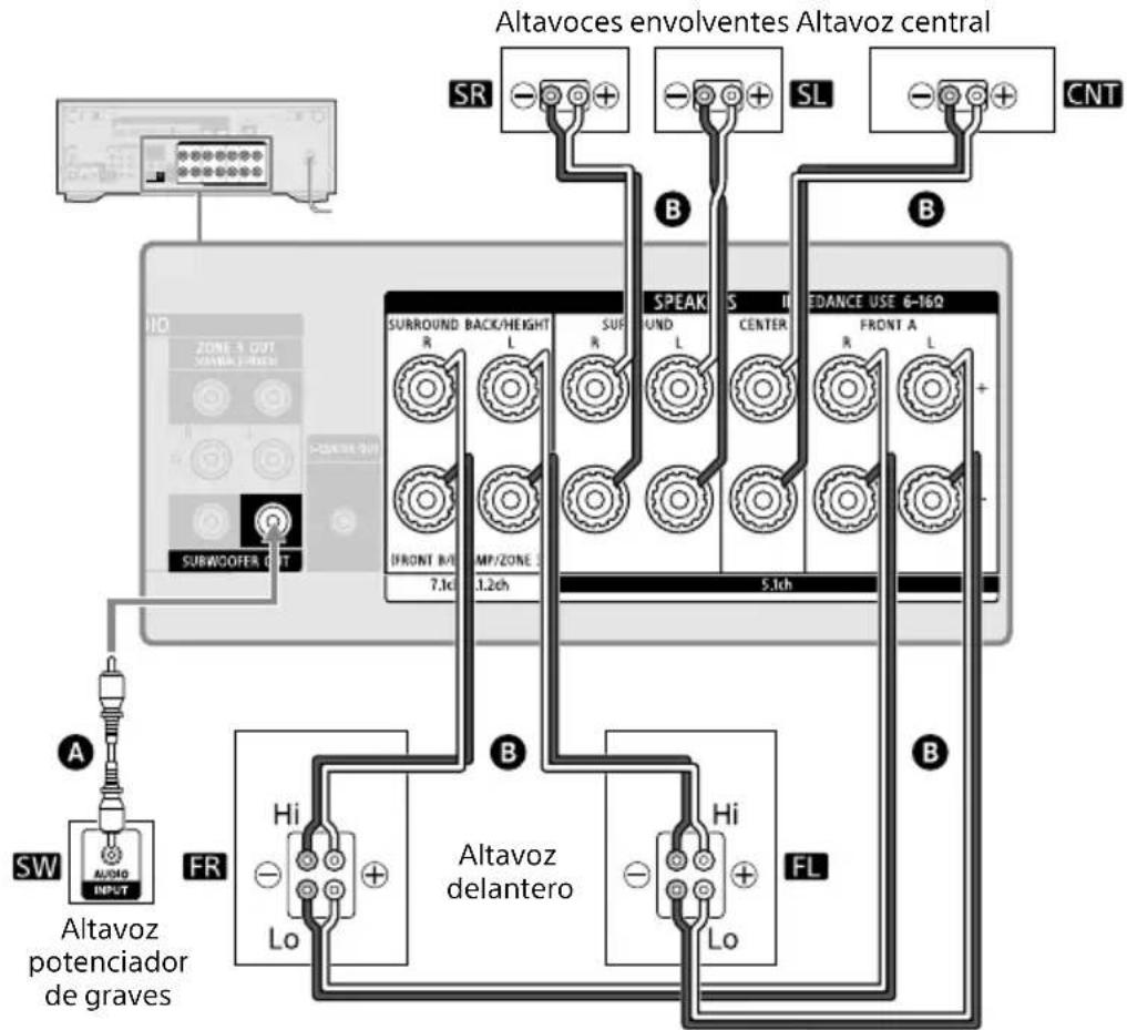
flowchart
graph TD
    A["HELLO"] --> B["PLEASEWAIT"]
    B --> C["Device"]
natural_image
Line drawing of a portable electronic device with buttons and a power switch (no text or symbols)Nota
natural_image
Two identical mechanical device setups with a cable and base, labeled ① and ② (no text or symbols on the devices themselves)Nota
- Chromecast built-in™
- Sony | Music Center
https://www.sony.com/am/support
flowchart
graph TD
    A["DL"] --> B["XXX%"]
    B --> C["UPDATEXXX%"]
    C --> D["Device with LCD panel"]
https://www.sony.com/am/support

S/N: 100 dB (A, 20 kHz LPF)
Digital (Óptica)
S/N: 100 dB (A, 20 kHz LPF)
Salida (Analógica)
ZONE 3
HDCP2.3, HDR (HDR10, Hybrid Log-Gamma, Dolby Vision), 3D, Deep Color,
ITU-R BT.2020, eARC/ARC, VRR, ALLM
Operating Instructions
SA-RS5
Owner's Record
The model and serial numbers are located on the bottom of the speakers.
Record the serial numbers in the space provided below. Refer to them whenever you call upon your Sony dealer regarding the speakers.
Model No. SA-RS5
Serial No
WARNING
The AC adaptor is not disconnected from the mains as long as it is connected to the AC outlet, even if the speakers themselves have been turned off.
To reduce the risk of fire, do not cover the ventilation opening of the speakers with newspapers, tablecloths, curtains, etc.
Do not expose the speakers to naked flame sources (for example, lighted candles).
To reduce the risk of fire or electric shock, do not expose these speakers to dripping or splashing, and do not place objects filled with liquids, such as vases, on the speakers.
As the mains plug of AC power adaptor is used to disconnect the AC power adaptor from the mains, connect it to an easily accessible AC outlet. Should you notice an abnormality in it, disconnect it from the AC outlet immediately.
Do not install the speakers in a confined space, such as a bookcase or built-in cabinet.
Do not expose batteries or appliances with battery-installed to excessive heat, such as sunshine and fire.
Do not place this product close to medical devices.
This product (including accessories) has magnet(s) which may interfere with pacemakers, programmable shunt valves for hydrocephalus treatment, or other medical devices. Do not place this product close to persons who use such medical devices. Consult your doctor before using this product if you use any such medical device.
RECYCLING RECHARGEABLE BATTERIES
Rechargeable batteries are recyclable. You can help preserve our environment by returning your used rechargeable batteries to the collection and recycling location nearest you.
For more information regarding recycling of rechargeable batteries, visit https://www.sony.com/electronics/eco/environmental-management
5-034-500-11(1)
©2022 Sony Corporation Printed in China
- Retain the original product literature for future reference.
- Do not expose the batteries (battery pack or batteries installed) to excessive heat such as sunshine, fire or the like for a long time.
- Do not subject the batteries to extreme low temperature conditions that may result in overheating and thermal runaway.
For customers in the U.S.A.
NOTE:
These speakers have been tested and found to comply with the limits for a Class B digital device, pursuant to Part 15 of the FCC Rules. These limits are designed to provide reasonable protection against harmful interference in a residential installation. These speakers generate, use and can radiate radio frequency energy and, if not installed and used in accordance with the instructions, may cause harmful interference to radio communications. However, there is no guarantee that interference will not occur in a particular installation. If these speakers do cause harmful interference to radio or television reception, which can be determined by turning the speakers off and on, the user is encouraged to try to correct the interference by one or more of the following measures:
- Reorient or relocate the receiving antenna.
- Increase the separation between the speakers and receiver.
- Connect the speakers into outlets on a circuit different from that to which the receiver is connected.
- Consult the dealer or an experienced radio/TV technician for help.
If you have any questions about this rear speaker: Visit: https://www.sony.com/electronics/support Contact: Sony Customer Information Service Center at 1-800-222-Sony (7669) Write: Sony Customer Information Service Center 12451 Gateway Blvd., Fort Myers, FL 33913
Supplier's Declaration of Conformity
Trade Name: SONY
Model No.: SA-RS5
Responsible Party: Sony Electronics Inc.
Address: 16535 Via Esprillo, San Diego, CA 92127 U.S.A.
Telephone No.: 858-942-2230
This device complies with part 15 of the FCC rules.
Operation is subject to the following two conditions: (1) This device may not cause harmful interference, and (2) this device must accept any interference received, including interference that may cause undesired operation.
For customers in Canada
These speakers contain licence-exempt transmitter(s)/receiver(s) that comply with Innovation, Science and Economic Development Canada's license-exempt RSS(s).
Operation is subject to the following two conditions:
(1) These speakers may not cause interference; and
(2) These speakers must accept any interference, including interference that may cause undesired operation of the speakers.
These speakers complies with ISED radiation exposure limits set forth for an uncontrolled environment and meets RSS-102 of the ISED radio frequency (RF) Exposure rules. These speakers should be installed and operated keeping the radiator at least 20cm or more away from person's body.
5.15 - 5.35 GHz band is restricted to indoor operations only.
Data transmission is always initiated by software, which is the passed down through the MAC, through the digital and analog baseband, and finally to the RF chip. Several special packets are initiated by the MAC. These are the only ways the digital baseband portion will turn on the RF transmitter, which it then turns off at the end of the packet. Therefore, the transmitter will be on only while one of the aforementioned packets is being transmitted. In other words, this device automatically discontinue transmission in case of either absence of information to transmit or operational failure.
Precautions
On safety
- Should any solid object or liquid fall into the rear speaker, unplug the rear speaker and have it checked by qualified personnel before operating it any further.
- Do not climb on the rear speaker, as you may fall down and injure yourself, or the rear speaker damage may result.
On the AC adaptor
Use only the supplied AC adaptor. To avoid damaging the unit, do not use any other AC adaptor.
On power sources
- Before operating the rear speaker, check that the operating voltage is identical to your local power supply. The operating voltage is indicated on the nameplate at the bottom of the rear speaker.
- If you are not going to use the rear speaker for a long time, be sure to disconnect the rear speaker from the wall outlet (mains). To disconnect the AC power cord (mains lead), grasp the plug itself; never pull the cord.
- One blade of the plug is wider than the other for the purpose of safety and will fit into the wall outlet (mains) in only one way. If you are unable to insert the plug fully into the outlet, contact your dealer.
- The AC power cord (mains lead) must be changed only at a qualified service shop.
On heat buildup
- Although the rear speaker heats up during operation, this is not a malfunction. If you continuously use this rear speaker at high volume, the rear speaker temperature at the rear and bottom rises considerably. To avoid burning yourself, do not touch the rear speaker.
On placement
- Do not place the rear speaker near heat sources or in a place subject to direct sunlight, excessive dust, or mechanical shock.
- Do not place metal objects other than a TV around the rear speaker. Wireless functions may be unstable.
- If the rear speaker is being used in combination with a TV, VCR, or tape deck, noise may result and picture quality may suffer. In such a case, place the rear speaker away from the TV, VCR, or tape deck.
- Use caution when placing the rear speaker on a surface that has been specially treated (with wax, oil, polish, etc.), as staining or discoloration of the surface may result.
- The speakers of this rear speaker are not of magnetically shielded type. Do not place magnetic cards on the rear speaker or near it.
If you encounter color irregularity on a nearby TV screen
Color irregularities may be observed on certain types of TV sets.
On cleaning
Clean the rear speaker with a soft, dry cloth. Do not use any type of abrasive pad, scouring powder, or solvent such as alcohol or benzine.
Others
- At high temperature, the charging may stop or the volume may reduce to protect the battery.
Caution: Do not handle damaged or leaking rechargeable batteries.
Indoor use only.
For the speakers
The nameplates are located on the bottom of the speakers.
For the AC adaptor
Labels for AC adaptor model No. and Serial No. are located at the bottom of the AC adaptor.
- Do not dismantle, open or shred secondary cells or batteries.
- In the event of a cell leaking, do not allow the liquid to come in contact with the skin or eyes. If contact has been made, wash the affected area with copious amounts of water and seek medical advice.
- Do not use any charger other than that specifically provided for use with the equipment.
- Secondary cells and batteries need to be charged before use. Always use the correct charger and refer to the manufacturer's instructions or equipment manual for proper charging instructions.
- After extended periods of storage, it may be necessary to charge and discharge the cells batteries several times to obtain maximum performance.
- Dispose of properly.
CAUTION
You are cautioned that any changes or modifications not expressly approved in this manual could void your authority to operate these speakers.
These speakers must not be co-located or operated in conjunction with any other antenna or transmitter.
These speakers comply with FCC radiation exposure limits set forth for an uncontrolled environment and meet the FCC radio frequency (RF) Exposure Guidelines. These speakers should be installed and operated keeping the radiator at least 20cm or more away from person's body.
Compliance with FCC requirement 15.407(c) Data transmission is always initiated by software, which is the passed down through the MAC, through the digital and analog baseband, and finally to the RF chip. Several special packets are initiated by the MAC. These are the only ways the digital baseband portion will turn on the RF transmitter, which it then turns off at the end of the packet. Therefore, the transmitter will be on only while one of the aforementioned packets is being transmitted. In other words, this device automatically discontinue transmission in case of either absence of information to transmit or operational failure.
Frequency Tolerance: ±20 ppm or less
- Even if you do not intend to use the rear speaker for a long time, charge the battery to its full capacity once every 6 months to maintain its performance.
- When the amount of time that the built-in battery can be used seems significantly shorter, it could mean that the rechargeable built-in battery has expired.
If you have any question or problem concerning your rear speaker, please consult your nearest Sony dealer.
About Compatible Models for the Rear Speaker
The SA-RS5 rear speaker works only with the specified model. For information about compatible models, visit Sony's website.
In these Operating Instructions, the operations are described for speakers used with the compatible model HT-A7000.
Note
You may need to update the software depending on the connected device. To update the rear speaker, you need to connect the rear speaker to the AC outlet (mains) using the AC adaptor (supplied). For details about updating, refer to Operating Instructions of the compatible model.
Note
When using th speaker stand off the cover of flathead screw side of the cov