FSP11330 - Power bank VOLTCRAFT - Free user manual and instructions
Find the device manual for free FSP11330 VOLTCRAFT in PDF.
| Product type | Stabilized fixed-voltage power supply |
| Brand | Voltcraft |
| Model | FSP11330 |
| Output voltage | 13.8 V DC |
| Continuous output current | 30 A |
| Temporary output current (max. 5 min) | 32 A |
| Continuous output power | 415 W |
| Mains power supply | 230 V~ (±10%) / 50 Hz |
| Protection class | 1 (with grounding) |
| Mains fuse | T4A/250 V (5 x 20 mm) |
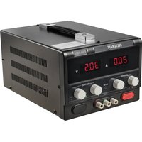
| Display | Needle instrument for DC current (ammeter) |
| Output terminals | Screw terminal sockets (red +, black -), compatible with 4 mm plugs |
| Cooling | Active fan |
| Operating temperature | +10°C to +35°C |
| Max. relative humidity | 85% (non-condensing) |
| Package contents | Power supply, instruction manual |
| Intended use | Connection of low-voltage consumers (12 V, 13.8 V or 24 V) |
| Maintenance | Cleaning with a clean, dry, antistatic cloth; fuse replacement |
| Safety | Protection against short circuits, overload and overheating |
| Care | No regular maintenance required except occasional cleaning |
Frequently Asked Questions - FSP11330 VOLTCRAFT
User questions about FSP11330 VOLTCRAFT
0 question about this device. Answer the ones you know or ask your own.
Ask a new question about this device
Download the instructions for your Power bank in PDF format for free! Find your manual FSP11330 - VOLTCRAFT and take your electronic device back in hand. On this page are published all the documents necessary for the use of your device. FSP11330 by VOLTCRAFT.
USER MANUAL FSP11330 VOLTCRAFT
Fixed-voltage Power Unit
GB OPERATING INSTRUCTIONS Page 15 - 25
© NOTICE D'ÉMLPOI Page 26 - 36
GB These Operating Instructions accompany this product. They contain important information on setting up and using your Voltage Detector. You should refer to these instructions, even if you are buying this product for someone else.
Please retain these Operating Instructions for future use!
The contents page on page 16 lists the contents of these instructions together with the relevant page number.
In purchasing this Voltcraft® product, you have made a very good decision for which we should like to thank you.
You have acquired an above-average quality product from a brand family which has distinguished itself in the field of measuring, charging and network technology by particular competence and permanent innovation.
With Voltcraft®, you will be equal to difficult tasks as an ambitious hobbyist just as much as a professional user. Voltcraft® offers you reliable technology at an extraordinarily favourable cost-performance ratio.
We are certain: your start with Voltcraft will at the same time be the commencement of a long and profitable co-operation.
We wish you much enjoyment with your new Voltcraft® product!
Table of Contents
Introduction 15
Table of Contents 16
Intended Use 16
Safety instructions and danger warnings ....18
Scope of delivery....20
Operating elements (see fold-out page) ......21
Commissioning 21
Connecting the mains cable 21
Connecting a consumer....21
Servicing and cleaning....23
Replacing the fuse 23
Troubleshooting....24
Disposal 25
Technical data ....25
Intended Use
These stabilised fixed-voltage power units are suitable for the connection and operation of extra-low-voltage consumers.
The following information is to be observed, depending on the device which you have purchased.
Model output voltage - max. output current
FSP-1122 12 Volt DC 2A continuous operation / transient 4A
FSP-1243 24 Volt DC 3A continuous operation / transient 5A
FSP-1132 13.8 Volt DC 2A continuous operation / transient 4A
FSP-1134 13.8 Volt DC 4A continuous operation / transient 6A
FSP-1136 13.8 Volt DC 6A continuous operation / transient 8A
FSP-1138 13.8 Volt DC 8A continuous operation / transient 10A
FSP-11312 13.8 Volt DC 12A continuous operation / transient 15A
FSP-11320 13.8 Volt DC 20A continuous operation / transient 22A
FSP-11330 13.8 Volt DC 30A continuous operation / transient 32A
The designation "transient" is defined with <5 minutes!
The indicator instrument supplies information about any output current.
If exceeded or in case of a short, this will lead with each of the power units listed to overloading and thus to destruction.
The power unit is structured in compliance with protection class 1. It is only approved for connection to shockproof sockets with protective grounding and an alternating current of 230V\~ /50 Hz commonly used in households.
Any use in damp rooms or outdoors or under adverse ambient conditions is not permitted. The following are adverse ambient conditions:
- wetness or excessive humidity
- dust or combustible gases, vapours or solvents,
- strong vibrations
Use other than that described above will damage the product and may involve other risks, such as shorts, fire or electric shock etc. Do not modify or convert any part of the product. The safety instructions have to be observed at all times!
Safety instructions and danger warnings

The guarantee will expire in case of damage caused by failure to comply with these operating instructions! We do not accept liability for damage to property or injury to persons caused by mishandling or non-compliance with the safety instructions.
This device left the factory in perfect condition in terms of safety engineering.
To maintain this status and ensure safe operation, you, as user, must comply with the safety instructions and warnings contained in these instructions for use. The following symbols must be observed:

Note! Read the instructions for use.

This equipment is CE-tested and complies with the EMC directive 89/336/EEC and the low-voltage directive 73/23/EEC.

Safety isolating transformer
- Electric appliances and accessories should be kept out of the reach of children!
- In commercial institutions, the accident prevention regulations of the Employer's Liability Insurance Association for Electrical Systems and Operating Materials are to be observed.
- In schools and training centres as well as at hobby and DIY workshops, the use of power packs must be supervised by adequately trained personnel in a responsible manner.
- For safety and licensing (CE) reasons, unauthorised conversion and/or modifications to the product are not permitted.
- Do not expose the device to high temperatures, dampness or strong vibration or excessive mechanical loads.
- Never touch the device or the plug with wet or moist hands. There is a risk of a fatal electric shock!
- Live components may be exposed if covers are opened or parts are removed unless this can be done by hand.
- Before opening it, disconnect the device from all voltage sources.
- Capacitors in the device may still be charged even if the device has been disconnected from all voltage sources.
- Never switch the power unit on immediately after it has been taken from a cold to a warm environment. Under adverse conditions, the resulting condensation could destroy the device. Allow the device to reach room temperature before switching on.
- The plug-in power unit generates heat during operation; ensure that it is adequately ventilated. Do not cover the ventilation apertures of the device!
- Do not leave mains power supplies and the connected consumers in operation unattended.
- Only fuses of the type stated and rated current specified may be used. The use of repaired fuses is not permitted under any circumstances.
- Avoid the use of bare metallic cables.
- In the case of series switching of the outputs of several power units, voltages (> 35 VDC) are generated which are dangerous if contacted.
- Power supply units are not designed for use on human beings or animals.
- The power unit is not a charger. To charge accumulators, use suitable chargers with a charging current cut-off.
- If you have reason to assume that safe operation is no longer possible, take the device out of operation immediately and secure it against inadvertent operation. It can be assumed that risk-free operation is no longer possible if
- the device shows visible signs of damage
- the device no longer functions and
- has been stored for longer periods under unfavourable conditions or
- has been subjected to considerable stress in transit.
- You should also observe the safety instructions in the individual sections or in the operating instructions of the connected devices.
Scope of delivery
*Fixed-voltage power unit Operating Instructions
Operating elements
(see fold-out page)
1 DC screw-terminal jacks (red = plus / black = minus)
2 Indicator instrument for DC current (ammeter)
3 Operating switch (I = ON / 0 = OFF)
4 Fan opening / device cooling
5 Refrigerating machine connection for mains cable
6 Fuse holder for the mains fuse
Commissioning

Before commissioning, both the intended purpose of use and the safety instructions and technical data are to be observed!
Make sure before commissioning that the device of suitable for the purpose of use for which it is to be used.
Connecting the mains cable
- Connect the optional earth-protected contact mains cable to the mains connection jack (5) on the power unit. Make sure it is plugged properly.
- Connect the mains cable to an earth-protected mains socket with earth wire.
- Switch on the power unit on the operating switch (3). The switch lights up during operation.
Connecting a consumer
In selecting the connecting cables (cable), make sure that the cable cross-section is adequate (on account of the current load/cable losses) and that the insulation is intact.
The output voltage is, depending on the type and design, fixed to 12 V or 13.8 V or 24 V direct voltage (=DC).
The rated current has, depending on the design of the device, a maximum of 30A.
For a period of a maximum of 5 minutes, the power unit can be exposed to a slightly higher load (always observe the "Intended Purpose of Use"!).
- Make sure the consumer is switched off.
- Connect the plus pole (+) of the consumer to the red terminal screw jack "+" (1) and
- the minus pole (-) of the consumer to the black terminal jack "-" (1).
- 4-mm standard connectors could be used for this purpose but we strongly recommend the connection through 20 A using terminal screw connectors (the jack heads can be screwed on!).
- The power consumption of the connected consumers is shown on the current display (2).

Make sure that the consumers are switched off when connected to the power unit. Sparks may be generated when a consumer which has been switched on is connected to the jacks. This may damage the terminal screw connectors as well as the connected cables.
If the power units are no longer required, disconnect them from the mains.
In the case of a short, the mains devices must be disconnected from any load within a maximum of 5 minutes as they can be destroyed otherwise.
In case of longer operation with the rated load (output voltage times output current), the surface of the housing or the cooling element becomes very hot.

Caution! Danger of burning! Therefore, make sure that there is adequate ventilation of the power unit and never operate it partly or fully covered to avoid any damage.
Servicing and cleaning
The power units are maintenance-free apart from the need to replace the fuses and cleaning them once in a while. Use a clean, lint-free, antistatic and dry cloth to clean the device. Do not use any abrasive or chemical agents or detergents containing solvents.
Replacing the fuse
If it is no longer possible to switch on the power unit, the mains fuse is probably defective.
Proceed as follows to replace the mains fuse:
- switch off the power unit and remove all the connection and mains cables.
- Release the bayonet lock on the fuse holder at the rear with slight pressure in the direction of the arrow (a quarter revolution).
- Replace the defective fuse with a new fine-wire fuse (5 x 20 mm) of the same type and rated current. You can find the fuse data in the technical data.
- Insert the fuse holder and lock it in the reverse order.

Make sure that only fuses of the type stated and rated current specified are used as a replacement. The use of repaired fuses or the bridging the fuse holder is not permitted.
Troubleshooting
By purchasing the power unit, you have acquired a product that is reliable and operationally safe.
However, problems and malfunctions can occur.
For this reason we want to describe how to eliminate potential malfunctions:

Always observe the safety instructions!
| Fault Possible cause | |
| The power unit Does the green operating switch (3) on the does not work power unit light up?Check the mains voltage (you may also want to check the mains fuse in the device or the earth switch). | |
| Connected Is the polarity correct?consumers: Is the power over unit overloaded (display 2)?do not function. Check the technical data of the consumers. | |
Check the technical safety of the device regularly for damage to the housing etc.

Any other repair work may only be carried out by specialists who are familiar with the hazards involved and with the relevant regulations. The warranty will lapse in the case of unauthorized modifications and repairs on or inside the device.
Disposal

If the product is no longer functional and can no longer be repaired, dispose of it in accordance with the relevant statutory regulations.
Technical data
Voltage supply ......230V\~(+/- 10%)/50Hz
Current indicator ....Indicator instrument class 5
Working temperature .....+10°C to +35°C
Rel. humidity ....max. 85 (non-condensing)
| Item-No. | Model Output | con- DC- DC- sumption vol | Output C o m pen- R i pple Fuse t ampere power sat ion 5x20 | |||||
| 51 14 10 | FSP-1122 | 50 Watt | 12V | 2(4)A | 25 W | 10mV | <2.5mV | T0.8A/250V |
| 51 14 09 | FSP-1243 | 120 Watt | 24V | 3(5)A | 72 W | <250mV | <5mV | T0.8A/250V |
| 51 07 87 | FSP-1132 | 60 Watt | 13.8V | 2(4)A | 30 W | 10mV | <2.5mV | T0.8A/250V |
| 51 07 88 | FSP-1134 | 100 Watt | 13.8V | 4(6)A | 55 W | 10mV | <2.5mV | T0.8A/250V |
| 51 08 00 | FSP-1136 | 140 Watt | 13.8V | 6(8)A | 85 W | <15mV | <2.5mV | T0.8A/250V |
| 51 08 01 | FSP-1138 | 180 Watt | 13.8V | 8(10)A | 110 W | <15mV | <2.5mV | T1.0A/250V |
| 51 08 32 | FSP-11312 | 400 Watt | 13.8V | 12(15)A | 165 w | <15mV | <2.5mV | T1.6A/250V |
| 51 14 22 | FSP-11320 | 450 Watt | 13.8V | 20(22)A | 280 W | <20mV | <30mV | T2.5A/250V |
| 51 14 26 | FSP-11330 | 680 Watt | 13.8V | 30(32)A | 415 W | <30mV | <50mV | T4A/250V |
The power figure in brackets demotes brief, maximum current drain for a maximum of 5 minutes.
F Introduction
Cher client,
© Copyright 2011 by Voltcraft®
GB Impressum /legal notice in our operating instructions
These operating instructions are a publication by Voltcraft®, Lindenweg 15, D-92242 Hirschau/Germany, Phone +49 180/586 582 7 (www.voltcraft.de).
All rights including translation reserved. Reproduction by any method, e.g. photocopy, microfilming, or the capture in electronic data processing systems require the prior written approval by the editor. Reprinting, also in part, is prohibited.
These operating instructions represent the technical status at the time of printing. Changes in technology and equipment reserved.
© Copyright 2011 by Voltcraft®
© Copyright 2011 by Voltcraft®
© Copyright 2011 by Voltcraft®
V4_0111_01/HK