66471 - Model making Märklin - Free user manual and instructions
Find the device manual for free 66471 Märklin in PDF.

| Product Type | Transformer for model railways |
| Brand | Märklin |
| Model | 66471 (32 VA) |
| Input Voltage | 230 V ~ 50/60 Hz |
| Output Voltage | 16 V~ (yellow terminal) ; 4-16/24 V~ (red terminal) |
| Power | 32 VA max, 2 A |
| Protection Rating | IP40 |
| Main Functions | Speed control, direction change, thermal protection |
| Usage | Märklin H0 and 1 layouts, alternating current |
| Approximate Dimensions | 100 x 60 x 80 mm |
| Approximate Weight | 0.5 kg |
| Maintenance and Cleaning | Check cord and housing regularly; do not use if damaged |
| Safety | Not suitable for children under 15 years; do not carry by cord; use on a fixed, dry surface |
| Spare Parts and Repairability | Cord not replaceable; repair only by Märklin service |
| Compatible Accessories | Power track K (2290, 2292), C track (74046, 74040), terminal set 5654 for track 1 |
| General Information | Compliant with EMC standards; indoor dry use only |
Frequently Asked Questions - 66471 Märklin
User questions about 66471 Märklin
0 question about this device. Answer the ones you know or ask your own.
Ask a new question about this device
Download the instructions for your Model making in PDF format for free! Find your manual 66471 - Märklin and take your electronic device back in hand. On this page are published all the documents necessary for the use of your device. 66471 by Märklin.
USER MANUAL 66471 Märklin
márklín
Transformer
66470
Deutsch 2
English 9
Français 16
Nederlands 23
Español 30
Italiano 37
Svenska 44
Dansk 51
Inhaltsverzeichnis
Dabei beachten.
natural_image
Three technical diagrams showing different types of electrical or mechanical components with cross-sectional views (no text or symbols)- Safety Information for the Operation of Märklin Transformers 10
- Connecting the Transformer 13
- Operations with the Transformer 14
- Short Circuit or Overload on a Transformer 15
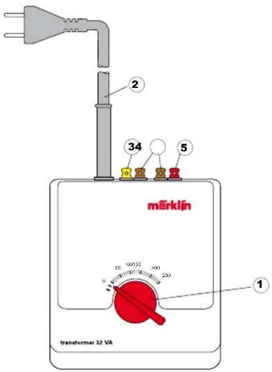
1 - Speed controller
2 - Power cord
3 - Yellow terminal clip ("L" = accessory power)
4 - Brown terminal clip ("0" = ground return)
5 - Red terminal clip ("B" = track power)
Not suitable for children under 15 years.
The transformer must not be moved while the train is being operated. After the transformer has been turned off, it must never be carried by holding it by its power cord.
- Read the following safety information before using a Märklin transformer for the first time:
- All transformers must be plugged only into an outlet with the household current indicated on the face plate of the transformer.
Example: Identification plate for the 230 volt transformer.

- This transformer is designed exclusively to be used indoors.
- Mount the transformer on a sturdy base. Never operate the transformer on a base that is wet or that is readily flammable.
- This transformer is not a toy. It is designed for the control of a model railroad layout.
- The transformer must be unplugged from the electrical outlet before being moved. If the transformer has been in operation, let it cool off before moving it.
- Inspect the condition of the power cord and the transformer housing at regular intervals for damage. This visual inspection should only be done when the power cords for all of the transformers being used are unplugged from the household current. If you have the least suspicion that the transformer is damaged, you should not use it again until it has been thoroughly inspected and repaired by an authorized service organization (example: Märklin Service Department). The power cord for the transformer must never be replaced. In this instance dispose of the transformer in an authorized manner, or send it to the Märklin Service Department for exchange.
The following safety precautions must always be observed when connecting more than one transformer to a model railroad layout or setup:
- The power cords for all existing transformers connected to the layout must first be unplugged when connecting electrical power consumers (examples: feeder connec-
- The alternating current outputs of two or more transformers must never be connected with one another.
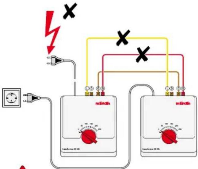
Important Safety Risk!
Under adverse conditions it is highly dangerous, if the yellow or red sockets/terminals for
two or more transformers are connected with each other in addition to the connections between the brown ground sockets/terminals. In such a situation if the power cord for
one transformer is still plugged into a household current outlet, a dangerous alternating current will be present in the bare metal parts of the power cords plugs for the other transformers.
Always observe the following:
The power cords for several transformers should therefore always be plugged into a common power distribution strip. The transformers must always be connected to or disconnected from the household current by plugging or unplugging the power cord for the distribution strip!
- Electrical power consumers (examples: feeder connections, turnouts, signals, lights, etc.) must never be connected to two or more transformers at the same time, because this situation will create the dangerous alternating current described above.
Important:
Two or more solenoid accessories connected together to a switch or to a circuit track must not receive their power from different transformers.
- Never touch any bare metal parts on a layout, before the entire layout is completely without power, i. e. all transformers must be disconnected from the household current.
- A locomotive must never be stopped continuously over the separation point between two track power circuits in conventional operation with alternating current transformers!
2. Connecting the Transformer
Make sure that the power cords for all of the transformers used with your layout are disconnected from the household current before connecting a transformer to the layout!
Possible Uses for the Transformer
Train operation with AC current for Märklin H0 or 1. Conventional hookup of turn outs and signal mechanisms. Conventional hookup of model railroad lighting.
Feeder Tracks
K Track: 2290, 2292
One 2292 interference suppression set should be used with each transformer used to operate trains.
Feeder Wire Sets
K-Track: 5904, C-Track: 74046, 74040
One 74046 interference suppression set should be used with each transformer used to operate trains.
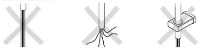
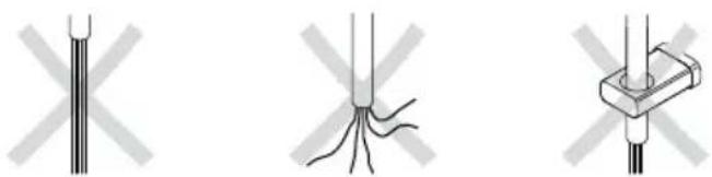
Preparing the wire and making connections with it
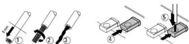
Pay particular attention when doing this
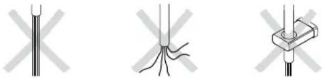
natural_image
Three technical diagrams showing different types of electrical or mechanical components with cross marks, no text or symbols present.Connect the red third rail wire from the feeder track to the red terminal clip ("B" = track power) on the 32 W Transformer. Then connect the brown ground return wire from the feeder track to the brown terminal clip ("0" = ground) on the 32 W Transformer → Figure 1, page 58.

Important!
The feeder wires from the layout to the transformer must never be plugged into a household power outlet. Make sure your children are aware of this danger!
Several feederTracks
On medium size and larger layouts power must be fed to the track at several points. We recommend that you install a feeder track every 2 to 3 meters (approx. 6 to 9 feet). Figure 2, page 58.
Several track circuits
In order to be able to control several locomotives separately, the layout must be divided into several track circuits by installing third rail insulators (7522 for K track, 74030 for C track). Each track circuit has its own 32 W Transformer with at least one feeder track. Please be sure to observe at all times the safety precautions given above when using several transformers → Figure 5 and 6, page 60/61.
Connecting the 32 W Transformer to Märklin 1 Layouts
The 32 W Transformer is suitable for use only in dry areas With Märklin 1 track the 5654 terminal clip set is used to feed power to the track. — Figure 3, page 59 One 104 770 interference suppression set should be used with each transformer used to operate trains.
Connecting Lights or Solenoid Accessories
Model railroad lights or solenoid accessories such as turnout or signal mechanisms are connected to the constant 16 volt AC current output on a transformer. All of the transformers described in these instructions have a pair of terminals for this connection (yellow + brown terminal clips).
Model railroad lights in buildings and/or street lights are connected directly to the yellow "L" terminal clip and brown "0" terminal clip on the 32 W Transformer.
The diagram for connections for model railroad lights can be found in Figure 4, page 59. The diagrams for connections for a turnout mechanism or a signal mechanism can be found in Figures 7 and 8, page 62/63.
Important: The model railroad lights or solenoid accessories connected to the transformer must be rated for 16 volts AC

A light or solenoid accessory must never be connected to two different transformers at the same time.
If two solenoid accessories are connected to the same circuit track or control box, then both solenoid accessories must be powered from the same transformer.
3. Operations with the Transformer
Model railroad with one transformer: Plug the power cord into a wall outlet.
Model railroad with several transformers: Plug the power cords for the transformers into a power strip and plug the power cord for the latter into a wall outlet. If you have a power strip with an on/off switch, turn this on after having carried out the steps above.
Operating Trains with the 32 W Transformer
The locomotive's speed is changed by turning the speed control knob on the 32 W Transformer.
Turn to the right – the locomotive runs faster
Turn to the left – the locomotive runs slower
Turn to the left to the "0" setting – the locomotive stops.
Changing direction
The locomotive's direction is reversed by turning the speed control knob to the left past the "0" setting.
4. Short Circuit or Overload on a Transformer
A built-in thermal switch protects the Transformer from damage in case of an overload or a short circuit. Locomotives on the layout will come to a stop, accessories cannot be operated and all lamps connected to the Transformer will go out.
The following procedure is recommended:
- Unplug the power cords for all transformers from their outlets.
- Look for the cause of the short circuit on the layout and correct it.
- After about 1 minute the thermal switch will go back to being on. After this amount of time has passed, all Transformers can be placed in operation again.
If the Transformer should shut off again and you are unable to locate a short circuit, then the Transformer is overloaded. In this case the number of users connected to the Transformer must be reduced.
Other Information
All Märklin products as delivered conform to the relevant regulations on preventing interference with radio and television reception. Worn out materials and/or faulty maintenance of the product as well as operation not in accordance with the instructions can lead to increased interference with radio and television reception. An information sheet on this subject is available on request.
The wiring diagrams that apply to the different turnouts or signals can be found in the instructions the come with these products.
Checking the Polarity
When two or more train control transformers for different track circuits are used on a layout, it may happen that different polarities for the transformers may cause a strong spark on the pickup shoe of a locomotive passing over the separation point between two track circuits. In this instance the plug on the power cord for one of the transformers must be removed from its outlet, turned 180° and plugged back into the outlet.
Table des matières
Attention aux risques!
Ne pas oublier
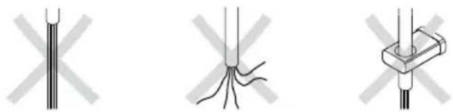
natural_image
Three technical diagrams showing different types of electrical or mechanical components with cross-hatching (no text or symbols)Let daarbij op
natural_image
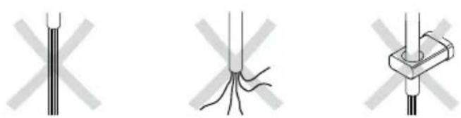
Three technical diagrams showing different types of electrical or mechanical components, including a vertical rod, branching wires, and a clamp (no text or symbols present)Detalles a observar
natural_image
Three technical diagrams showing different types of electrical or mechanical components, including a rod, wires, and a bracket (no text or symbols present)natural_image
Three technical diagrams showing different types of electrical or mechanical components with cross-sectional views (no text or symbols)Observera därvid

natural_image
Three technical diagrams showing different types of electrical or mechanical components with cross-hatching (no text or symbols)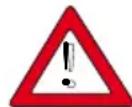
Læg her mærke til