
HDPD90 - Receiver ALPINE - Free user manual and instructions
Find the device manual for free HDPD90 ALPINE in PDF.

| Product Type | Digital Audio Receiver with Signal Processor (DSP) |
| Brand / Model | Alpine HDPD90 |
| Dimensions (W x D x H) | 278 mm x 256 mm x 58 mm |
| Net Weight | 4.5 kg |
| Supply Voltage | 9 ~ 16 V (12V negative ground) |
| Standby Power Consumption | ≤ 0.1 W |
| Output Power (nominal) | CH1~8 : 50W per channel (4Ω, 14.4V, 10% THD) ; CH9~12 : 80W per channel |
| Total Harmonic Distortion | ≤ 0.01% (4Ω, 1W) |
| Signal-to-Noise Ratio | ≥ 100 dB (A-weighted) |
| Frequency Response | 20 Hz ~ 40 kHz (4Ω, 1W) |
| Sampling Rate | 192 kHz / 32 bits |
| Number of Input Channels | 12 high-level channels + 2 RCA channels + optical + coaxial + Bluetooth |
| Number of Output Channels | 12 high-level channels + 10 RCA channels |
| Built-in Equalizer | Input: 10-band parametric/graphic ; Output: 31-band parametric/graphic |
| Built-in Filters | Independent high-pass and low-pass per channel (Linkwitz-Riley, Bessel, Butterworth) |
| Connectivity | USB 2.0 (for PC), High-definition Bluetooth, control wire (sold separately) |
| Software Functions | PC software for advanced settings (Windows XP/7/8/10), signal generator, RTA |
| Preset Sound Effects | 6 storable effect data groups |
| Adjustable Output Delay | 0 ~ 20 ms (0 ~ 692 cm, 0 ~ 273 inches) |
| Care and Cleaning | Use a soft, dry cloth ; do not use solvents |
| Operating Temperature | -20°C to +60°C (inside vehicle) |
| Box Contents | Main unit, 2x13P input cable, USB 2.0 cable, mechanical screws ×4, self-tapping screws ×4, mounting bracket |
| Warranty / Support | See full manual ; repair by authorized Alpine dealer |
Frequently Asked Questions - HDPD90 ALPINE
User questions about HDPD90 ALPINE
0 question about this device. Answer the ones you know or ask your own.
Ask a new question about this device
Download the instructions for your Receiver in PDF format for free! Find your manual HDPD90 - ALPINE and take your electronic device back in hand. On this page are published all the documents necessary for the use of your device. HDPD90 by ALPINE.
USER MANUAL HDPD90 ALPINE
Accessory List ....4
Connections and Functions ...... 5
Connections and Functions ...... 6
Indicators 7
Computer S software 8
Precautions installation .... 8
Computer S software Introduction .8
Connection and Temperature Display 9
Connection Settings 9
Temperature Display 9
File Settings 9
Option Setting 9
Signal Generator Settings .....10
Signal Selection ...... 10
Volume 10
Sine Wave Frequency ..... 10
Output Signal Selection .....10
Input Link Settings ....10
Output Link Settings 10
Built-in AMP ....10
Firmware Up date Settings .....11
Restore Factory Settings ......11
Shutdown dela y setting .....11
Language Settings ...... 11
View A bout 11
Encrypti on Settings 11
Master volume setting 12
Function Page Select ion ...... 12
Home Page 12
Main Source Selection ..... 13
Main Source Attenuation
Setting 13
Mix Source Selection .....13
Preset Sound Effect Settings13
Enter EQ 13
Type selection 13
Channel Mute Setting ..... 14
Link Settings 14
EQ Adjustment 14
Equalizer Settings ...... 15
Channel Settings ...... 16
X-Over 16
Output EQ 16
Bridge Mode 16
Delay 17
Mix 17
RTA 17
Specifications 19
Function Parameter 20
Instr uctions
Warning
Points for Safe Use
- Please read this manual carefully before using the machine and system components. This manual contains instructions on how to use this product safely and effectively. If failure to follow the instructions in this manual causes malfunctions, Alpine will not assume any responsibility.
- This manual uses various i cons to explain how to use this product safely, and reminds you to pay attention to the dangers that may be caused by improper connection and operation. The meaning of these icons will be explained below. A complete understanding of the meaning of these icons is very important for the correct use of this manual and this is system.

Warning
- It is very dangerous to operate this system while driving. The user should stop before operating the software.
- Road conditions and laws take precedence over the information displayed on the map: When driving, you should abide by actual traffic restrictions and conditions.
- This software is specially designed for this machine and cannot be used in combination with other hardware.

Warning
This symbol indicates important instructions. Failure to heed these instructions can result in serious injury or even death.
Do not use any features that will d istract you while d riving
Any function that affects your concentration should only be used a fter t he car h as come to a complete stop. To use these functions, please park your vehicle i n a safe place first. Otherw ise, an accident may result.
Do not disass emb le or mod ify Otherw ise, it may cause an accident, fire or electric shock.
The volum e must be mainta ined at a level where t he noise outside t he c ar c an be hea rd while d riving Inaudible emergency v ehicle sirens and road warning signals (train in intersections, etc.) are very dangerous and may cause accidents. In addition, excessive volume may cause hearing loss.
This product is only suitable for cars with 12V negative grounding Other wise, it may cause a fire and other accidents.
Smal l o bje cts s uch as bol ts o r sc rews sh ould be kept ou t o f t he reach of c hild ren Swallowing small objects may cause serious injury. Once swallowed by mistake, please immediately medical.
When replacing the fuse, you must choose a fuse with the correct amp ere va lue Otherw ise, it may cause a fire or electric shock.
Do not block the ventilation hole so heat sink. Otherwise, it may cause internal heat build-up and may cause a fire.
This product can only be used in 12V mobile applications If used in n on-designed application s, it may cause fire, electric shock or other injuries.
Make the correct connecti on If it is not connected properly, it may cause fire or product damage.
Before wiring, disconnect the cable from the negative terminal of the battery Otherwise, it may cause electric shock or injury due to electrical short circuit.
Do not let the cable be entang led with sur rounding objects
Arrange the wires and cables in accordance with the requirement s of the manu al to prevent them from becoming obstructive while driving. Cables or wires that obstruct or hang on the steering wheel, s hift lever, brake pedal, etc. are extremely dangerous.
Do not splice cables
Do not cut the cable insulation to supply power to other equipment. Other wise, the current carrying capacity of the wire will be exceeded, resulting in fire or electric shock.
Do not damage the pipe or wiring when dri lling When drilling holes in the chassis for installation, be careful not to touch, damage or obstruct the pipes, fuel lines, fuel tanks or wires. If you don't pay attention, it can cause fire.
Do not use b olts or nuts in brakes or steering systems for grounding conne ctions
Never use bolts or nuts used in brakes or steering systems (or any other safety-related systems) or fuel tanks for installation or grounding connections. The use of such parts will cause the car controller to fail, resulting in fire and so on.
Do not install on the steering wheel or gear leve r, etc., which may h inde r th e o peration of the car
Otherw ise, it will obstruct the front line of sigh t or obstruct moving parts, etc., causing serious accidents.

Notice
This symbol indicates important instructions. Failure to heed these instructions may result in injury or major property damage.
When there is a p problem, p lease stop using it imme diately
Otherw ise, it may cause personal i injury or damage to th e product. Please return this product to an authorized Alpine dealer or the nearest Alpine serv ice center for repair.
As k professional s for wiring and installation The wiring and installation of this product require professional skills and experience. For safety reasons, please contact the dealer where you purchased the product for installation.
Use designated accessories and install securely. Make sure to use only designated accessories.
The use of n on-designated parts may cause internal damage to the device, or it may not be securely installed in place. This can cause parts to loosen and cause danger or product failure.
Arrange the wires to avoid crimping or being sq ueezed by sharp metal edges
The arrangement of wires and cables should be far away from moving parts (such as seat tracks) or sharp edges or corners. This will a void crimping and damage to the wires. If the wiring passes through a metal hole, a rubber gasket should be used to prevent the wire in sulation from being cut by the edge of the metal hole.
Do not install in high humidity or dusty location s
Avoid installing the device in a location with high humidity or dust. Moisture or dust invades the device and can cause product failure.

Precautions
Prod uct cleaning
Please use a dry soft cloth to clean the product regularly. If the dirt is difficult to remove, soak a soft cloth with water only. An y other solvent may disolve.
temperature
Before turning on the machine, please make sure that the temperature in the car is between +60°C and -20°C.
Maintai n
If you encounter a problem, do not repair it yourself. Please return this product to an authorized Alpine dealer or the nearest Alpine service center for repair.
Installation lo cation
- This machine cannot be installed in any of the following places:
• Near direct sunlight and heat sources
- Places with high humidity and near water
sources
- Dusty places
- Locations subject to severe vibration
Copyright Notice
The Bluetooth® word mark and logo are registered trademarks held by Bluetooth SIG, Inc. Alpine Electronics has obtained permission to use the word mark and logo, and other trademarks and trade names belong to their respective owners.
Preparati on work
Accessory List
| Machine Screw×4 | Self-tapping Screw×4 | Mounting Brackets × 2 |
 |  |  |
| 2×13P Input Cable | USB 2.0 Cable | External Bluetooth Module |
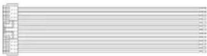 |  | 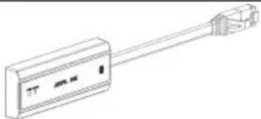 |
| Main Unit | ||
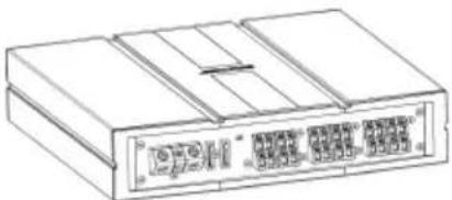 | ||
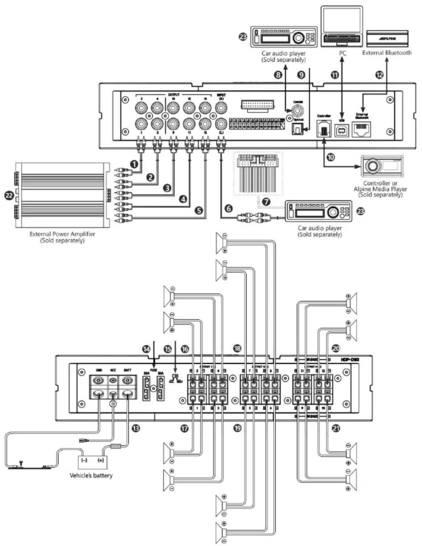
①②③④⑤ Pre-Out jacks
5 groups of RCA audio signal output, which can be connected to an external power amplifier.
⑥ RC A Audio Input jac ks
1 groups of RCA audio signal in put, which can be connected to the RCA audio signal output of car a udio player.
⑦ High Level Input Connector
Connect to the high-level output of the car audio player.
⑧ C oaxial Input j ack
Connect the car audi o coaxial cable, switch the audio s ource of the machine to the digital signal i nput, and play the coaxial digital signal.
⑨ Optical Input jack
Connect the car audio optical fiber cable, switch the audio source of the e mac hine to the digital signal input, and play the optical digital signal.
⑩ C ontroller Conn ector (Sold se parately)
System expansion interface.
⑪ US B 2.0 connector
It can be connected to a computer via a USB 2.0 ca ble for detailed tunin g operations and settings.
⑫ External Bluetooth connector
Choose high-definit ion Bluetooth as the input signal, or connect HDP-D90 mobil e phone tuning software. After the connection is successful, the Blu etooth is always on.
⑬ Power Supply Terminal
Connect the car battery.
⑭ Fuse
When the switch is pulled to the "ACC" terminal, ACC starts the machine; when it is pulled to the "HOST" terminal, the machine is started by the high level input signal H1-/H1+.
⑯⑰ C H1-4 S peaker Outp ut Terminals
The a multiplier output of the machine is connected to the speaker.
⑱⑲ C H5-8 S peaker Outp ut Terminals
The a multiplier output of the machine is connected to the speaker.
⑳ C H9-12 Speaker Out put Terminal s
The a multiplier output of the machine is connected to the speaker.
External Power Amplifier (So ld se parately)
Connect an external power amplifier r.
□ C ar Audio Player ( Sold se parately)
Connect the car audio player.
To prevent external noise from entering the audio system.
- The in stallation position of the machi ne and t he wiring arrangement s hould be at least 10cm away from t he automobile wiring harness.
• Try to keep the battery power cord away from other wires. - Securely connect the ground wire to the bare metal contacts of the car chassis (remove any paint, dirt or grease if necessary).
- If you want to attach an optional noise suppressor, please try to keep it away from the machine when connecting. Your Alpine dealer has various types of noise suppressors, please contact them for details.
- Your Alpine dealer is proficient in noise prevention methods, please consult your dealer for details.
Indicators
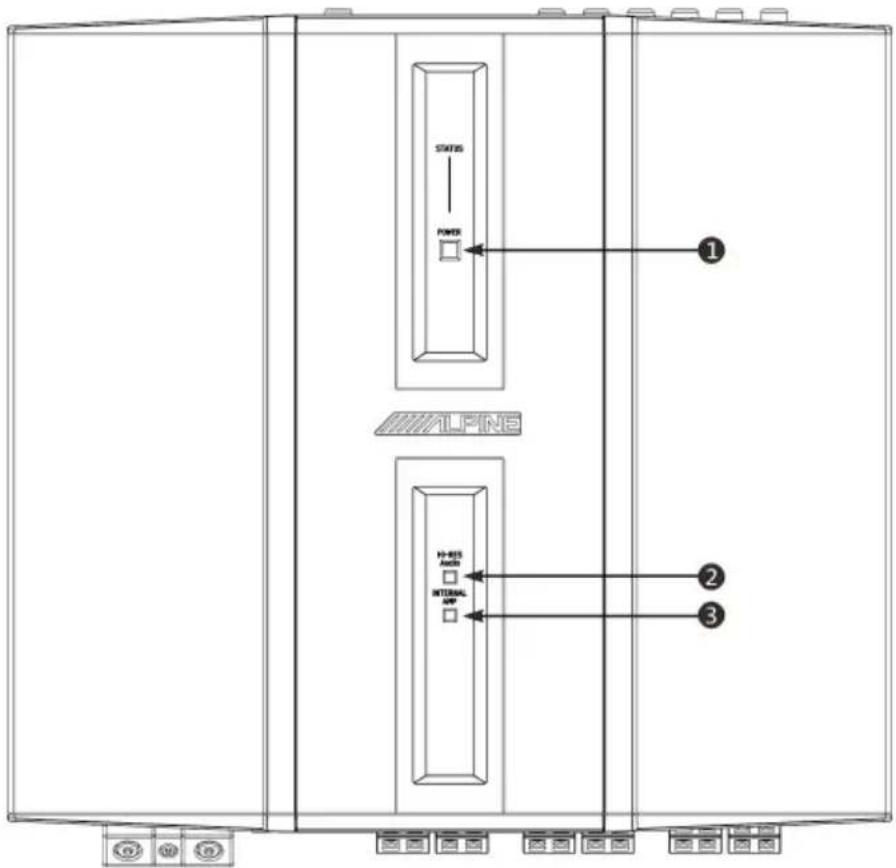
① Power and Protection Indi cator
Within 2 seconds of booting, the indicator light will show red;
In the protection state, the indicator light shows red light;
When working normally, the indicator light shows blue light ;
When s hutting down, t he indicator light is off.
② H i-Res S signal Indicator
When the optical fiber/coaxial input signal is Hi-Res standard signal, the in dicator light is always on (red light);
When there is no Hi -Res standard sign al for analog input and optical/coaxial input signal, the indicator light t is off.
③ Internal Amplifier Indicator
When the Internal power amplifier is turned on, the indicator light is always on (red light);
When the Internal power amplifier is turned off, the indi cator light goes out.
Computer Software
Precautions installation
- The software can only be used under the Microsoft ® Windows ® operating system.
Operating system: Windows XP, Windows Vista, Windows 7, Windows 8, Wind ows 10
CPU : 1.6GHz or higher
Memory card: 1GB or higher
Hard Disk: 512MB or more free space
Computer screen resolution: 1280*768 or high er
- Before connecting the HDP-D90 machine to the computer, please in stall the HDP-D90 computer software correctly.
• After installing the HDP-D90 software, you can tune and set the HDP-D90 mac hine on the computer.
*This function is mainly for manufacturers and distributors.
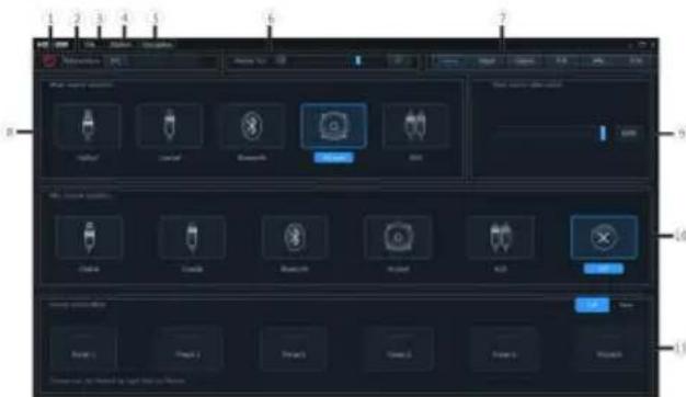
Computer Software Introduction
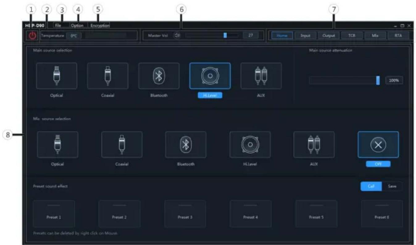
1 The host is powered on.
2 Connect one end of the USB 2.0 cable to the "USB" port of the host, and connect the other end to the USB port of the computer.
3 Double-click t he HDP-D90 software icon to open the software.
① Online switch.
② Temperature display.
③ Load or save the tuning file.
④ Select the function setting.
⑤ Encryption and decryption of tuning data.
⑥ Adjust the total volume.
⑦ Function page selection.
⑧ Editing area of function page
Connection and Temperature Display
Setting items:
Connection and temperature display
Setting content:
Connection/disconnected/temperature display
Connection Settings
1 Connect the USB cable and open the software, it will automatically go on line.
After the connection is successful, the connection icon will show green [ ]°

2 After online, click the connection icon to disconnect. When not online, the connect
icon will display red [ ], and click the connection icon again to go online again.
Temperature Display
Detect the temperature on the surface of the machine and display the current temperature value.

File Settings
Click [File] to enter the loading or saving scene file page.
■ Load or save presets file page
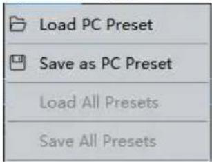
Setting items:File
Setting content: Load PC Preset/Save as PC
Preset/Load All Presets/Save All Presets
Load PC Preset
The scene file previously saved on the
computer can be loaded as the current machine working scene.
Save as PC Preset
The current machine work scene file can be saved to the computer for later recall.
Load All Presets
Load the files of t he entire mac hine previously saved on the computer to the machine (including the current work ing scene, machine preset scene, output chan nel configuration data, etc.), and copy all the mach ine data that has been debugged to the e currently connected machine.
Save All Presets
Save all data on the current online machine as a computer file (including the current working scene, machine preset scene, out put channel configuration data, etc.) for later recall when the whole machine is copied.
Option Setting
Click [Option] to enter the setting page.
■ Setting page
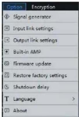
| Signal generator | |
| Signal select ion | |
| Volume | |
| Sine wave frequency | |
| Output signal selection | |
| Input link settings | |
| Output link settings | |
| Built-in AMP | |
| Firmware update | |
| Restore factory settings | |
| Shutdown delay | |
| Language | |
| About | |
Signal Generator Settings
Select [Signal Generator] from the opt ion page to enter the signal generator setting page.
■ Signal generator page
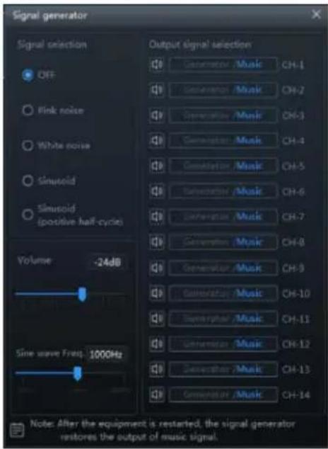
Test whether the out put signal is normal when there is no music playing.
Signal Selection
Setting item: signal selection
Setting content: OFF (initial setting)/pink noise/white noise/sinu solid/sinu solid(positiv e half-cycle)
Volume
Setting item: volume
Setting content: -60dB\~0dB (Initial setting: -24dB)
Sine Wave Frequency
Setting item: sine wave frequency
Setting content: 20Hz\~40kHz (initial setting: 1000Hz)
Output Signal Selection
Setting item: output signal selection
Setting content: generator/music output (initial setting)
Input Link Settings
Select [Input link settings] from the option page to enter the input link settings page.
■ Enter the input link settings page

Setting items: setting the functions that need to be combined with input
Setting content: channel EQ/X-Over/channel phase/channel volum e/channel mute
Output Link Settings
Select [Output link settings] from the option page to enter the ou tput link settings setting page.
■ Output link settings setting page
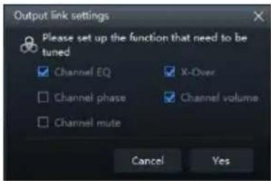
Setting item: Set the function that needs to be combined with the output
Setting content: chann el
EQ/X-Over/channel phase/channel
volume/channel mute
Built-in AMP
Select [Built-in AMP] from the options page to enter the build t-in power amplifier setting page.
■ Built-in AMP page

Setting item: Built-in AMP
Setting content: on (in itial setting) / off
Firmware Update Settings
Select [Firmware Update] from the options page to enter the firmware update setting page.
■ Firmware update page

Setting item: Firmware update
1 Click the ">" button to select the upgrade file.
2 Click the "Update" button to upgrade the firmware. The upgrade progress reaches 100%, indicating that the firmware upgrade is successful.
3 Click the "OK" button to exit the firmware update. After t he update, the machine will automatically restart to work.
Select [Restore Factory Settings] from the options page to enter the factory reset page.
■ Restore factory settings page

Setting item: restore factory settings
1 Click the "OK" button to restore all the data set in the e machine to the factory default state.
Shutdown delay setting
Select [Shutdown Dela y] from the e options page to enter the sh utdown delay setting page.
■ Shutdown delay page

Setting item: shutdown del ay
Setting content: 0\~255s (initial value: 0s)
Language Settings
Setting item: langua ge
Setting content: Chinese/English
View About
Select [About] from the options page to enter the about page.
■ About page

You can view the version number.
Encryption Settings
Click [Encry ption] to enter the encry ption page, and click [Decr ypt] to enter the decr yption page.
■ Encrypti on/decryption page


Setting item: encryption/decryption
1 Encrypti on: Enter the password to encrypt the tuning data.
2 Decry ption: You can enter a pa ssword, clear data or restore factory settings.
- The initial password is: "888 888".
- Encryption of EQ frequency, Q value, gain, delay, ch annel, ph ase equ alizer and other tuning data.
- Encryption only encrypts a single group of audio data currently in use, not all data of the whole machi ne.
- The encry pted sound data data can be stored as preset sound effects or computer files, and copying a nd transmission will not affect the encry pted state.
Master volume setting

Setting item: Master volume
Setting content: 0\~35 (initial value: 27)
1 You can adjust the total volume by pressing and holding the left mouse button, dragging the volume fader left or right, or scrolling the mouse wheel.
2 Click the main volume【】button to set the total volume mute【】click again to cancel the mute (it will a automatically cancel the mute when the main volume is adjusted).
Function Page Selection
The function page can be switched.

| Home page | |
| Main source selection | |
| Main source attenuation setting | |
| Mix source s election | |
| Preset s ound effects | |
| Input EQ | |
| Output EO | |
| TCR | |
| Mix | |
| RTA | |
Home Page
■ Home page
Main source attenuation/Mix
source selecti on/Preset sound effects
Main Source Selection

Setting items: Main source selection
Setting content: Optical/Coaxial/Bluetooth/
High Level/AUX
Main Source Attenuation Setting

You can press and hold the left button of the mouse to move the fader left or right or scroll the mouse wheel, or press the up and down keys of the keyboard to set the attenuation. The Mix source is equivalent to mixing g. The greater the attenuation of the main sound source, the lower the main volume, adjustable value: 0%\~100%.
Setting items: Main source attenuation
Setting content: 0% to 100% (default 100%)
- Note: When the current audio source mode is selected, the audio source mode can no longer be superim posed, otherwise the Mix source is invalid, and the optical fiber and coaxial cannot be mixed and superimposed.
Mix Source Selection

Setting items:Mix source
selection
Setting content: Optical/Coaxial/Bluetooth/
High Level/AUX/OFF
Preset Sound Effect Settings

1 Click [Call] to recall the pre-stored sound
effects.
2 Click [Save] to store the adjusted sound effect data.
3 Click the right mouse button to delete the preset sound effects. Or [Save] 6 groups of preset sound effects can be set
Setting items: Preset s ound effect settings
Setting content: Call/save/delete
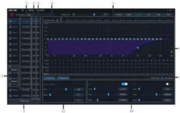
Enter EQ
■ Enter EQ page
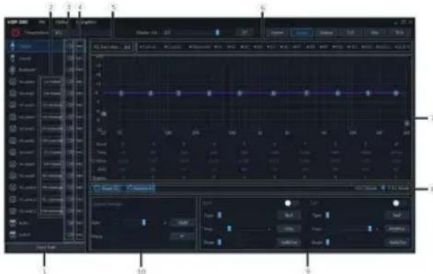
Setting items: Enter EQ
Setting content: Type selection/channel mute/link setting/EQ a djustment/equalizer setting/channel setting /X-Over setting
① Click to enter the in put type selection box.
② Customize the input channel type.
③ Mute button.
④ Joint adjustment button.
⑤ EQ gain step selection.
⑥ Chan nel display sele ction button.
⑦ EQ editing and display area.
⑧ Equalizer settings.
⑨ X-Over.
⑩ Chan nel settings.
Type selection
Custom input channel type
You can configure your favorite channel type according to your hobby.
■ Input type custom page
1 Click the channel type custom box.
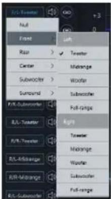
2 Select the input channel type in the pop-u p window. Set the input type in the input type setting dialog box. There are tweeter, midrange, woofer, subwoofer and full-range options in the front; tweeter, midrange, woofer, subwoofer and full-range options are available in the rear; F/C-tweeter, F/C-mid range, R/C-tweeter and R/C-midrange options are available in the center; L-subwoofer, R-subwoofer and C-subwoofer options are available in the subwoofer; L-surround and R-surround options are available in the surround;
Input type selection
■ Input type selection page
1 Select the desired channel type.
2 Click the [Enter] button to configure the channel type. At this time, the input channel type is fixed and cannot be configured.
3 S elect Customized or [Clear] to clear all input channel types. At this time, you can customize the input channel types.
Channel Mut e Setting
Setting items: Channel mute Setting content: Mute/off
Link Settings
■ Link group page

1 Select the input link function in the options, refer to "Input link settings" (refer to page 10).
2 Click t he link button.
3 Select the link group on the link selection page.
Setting items:Link
Setting content: Joint debuggin g 1/
joint debu gging 2/j oint 3/j oint 4/joint 5/ joint 6/joint 7/j oint 8/cancel link
EQ Adjustment
The input h as 10 bands of EQ adjustable, and there are two in terfaces of graphic equalization and parametric equalization.
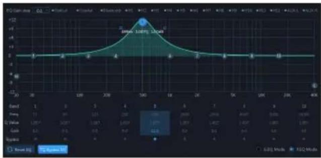
PEG page
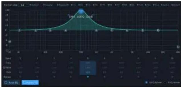
GEQ page
EQ gain step
Setting items: EQ gain step
Setting content:0.1 (in itial setting)/0.5/1
EQ curve display
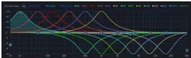
Click the channel display selection button to display the curve of the channel.
EQ settings
1 Select the input channel to be adjusted.
2 When the mouse moves to the serial number position, hold down, drag up and down to adjust the equalizer gain, drag left and right to adjust the equalizer frequency; when the mouse moves to the left and right blue boxes, hold down and drag to adjust the equalizer Q value. You can also set the frequency, Q value and gain by directly inputting the value, scrolling the mouse wheel, and the up and down keys on the keyboard.
Adjustable frequency range: 20Hz\~40kHz; Adjustable range of Q value: 0.404\~28.852;
Gain adju stable range: -12.0 dB \~+ 12.0 dB.
- Note: The gain is adjustable in the graphic equalization interface, and the frequency and Q value are not adjustable. In the parameter equalization interface, the frequency, Q value and gain are
adjustable.
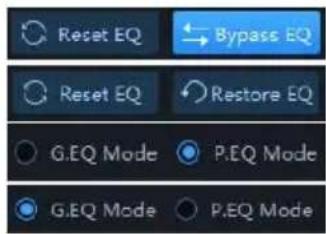
Equalizer Settings
-
When there is EQ adjustment, the direct equalization button appears.
-
Through Equalization: When the current channel equalize r is turned on, this button will be displayed [ ], click [Through Equalization] or the through dot to make a ll equalizers of the current channel inactive (through).
-
After clicking the "Yes" button, the button will be restored to the [R estore Balan ce] state [ Reset EQ Restore EQ ]. Then click [Restore EQ] and all equalizers of the current channel will return to the last activated state.
-
Click [Reset EQ], the parameters of all equalizers of the current channel return to the initial state: the frequency is evenly distributed, the input Q value is 2.515, the output Q value is 1.007, and the gain is 0.0dB.
-
Click [Parametric Equalization] to pop up a warning box "Confirm GEQ to PEQ mo de?", press OK to switch to [Graphic Equalization], click [Graphic Equalization] to pop up a warning box "Confirm PEQ to GEQ mo de?", press OK to confirm Switch [parameter equalization]. In the parametric equalization mode, the frequency, Q value and gain are adju stable, while in the graphic equalizer mod e, the frequency and Q value are fixed, and only the equ alizer gain can be adjusted.
Channel Settings
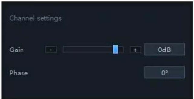
Setting items: Preset sound effect settings Setting content: Gain/phase
- Gain setting: The gain can be adjusted by directly inputting the value, scrolling the mouse wheel, the up and down keys on the keyboard, or clicking g "-" or "+". Adjustable range: -60dB\~6dB.
- Phase setting: normal phase or reverse phase s witch.
X-Over

Setting items:X-Over settings
Setting content: Type/frequency y/slope
- Type settings: Link-Ril, Besse l and Butter-W.
- Frequency setting: The frequen cy can be adjusted by directly i nputting t he value, scrolling the mouse wheel, th e up and down keys on the keyboard, or clicking "-" or "+". Adjustable range: 20Hz\~40000Hz.
- Slope (slope) setting: the drop-d own menu options are -6dB /Oct, -12dB/Oct, -18dB /Oct, -24dB /Oct, -30dB/Oct, -36dB /Oct, -42dB /Oct, -48dB/ Oct is optional.
- Note: When the slope is -6 dB/Oct, the type is displayed as "Null".
Output EQ
■ Output EQ page
Setting items: Output EQ
Setting content: Type selection/channel mute/link setting /EQ adjustment/ Bridge Mode equalizer setting/channel setting/X-Over setting
① Click to enter the ou tput type selecti on box.
② Stereo and handover switch.
③ Customize the output channel type.
④ Mute button.
⑤ Joint debugging button.
⑥ EQ gain step selection.
⑦ Chan nel dis play s election button.
⑧ EQ editing and display area.
⑨ Equalizer settings.
⑩ X-Over.
⑪ Chan nel settings.
Type selection of ou tput EQ settings, ch annel mute, joint tuning settings, EQ adjustment, equalizer settings, channel settings, filter settings refer to "Input EQ Settings" (page 13 to page 16)
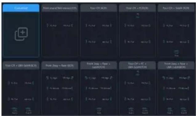
Bridge Mode
The output channel 9 can be bridged with the output channel 11, and the output channel 11 can be bridged with the output channel 12. The power can be increased in bridge mode.
Delay

① Delay adjustment.
② Delay group selection.
③ Delay value display window.
Setting items: Delay setting
Setting content: Delay/delay group
- Delay adjust ment: The delay can be adjusted by directly in putting the value, scrolling the mouse wheel or the up and down keys on the keyboard.
- Delay group: select the delay group, and the channels with t he same dela y group can be adjusted together.
- The delay units a re ms (milliseconds), in ch (inches) and cm (centimeters).
Delay range: 0.000\~20 .000 milliseconds;
0\~692 cm;
0\~273 in ches.
Mix

After the HDP D90 machine set s the sound source signal in to the audio processor, it is divided into the e volume of each output channel,
and the purpose of mixing and mixing can be achieved by adjusting the volume of each sound source in the channel. In the passive input mod e, the frequency division is set by the PC terminal; in the active input mode, the frequency division is set by the original vehicle host it self.
RTA

- Display window: The window size can be the largest screen and can be zoomed freely.
- Select the display channel:
(1) Output : Click t he drop-down list to select the spectrum dynamics of the output channel.
(2) Fixed: Only the spectrum dynamics of the currently selected output channel can be displayed, and other output channels cannot be switched.
(3) Follow: Follow the output channel clicked by the mouse to switch and display the spectrum dynamics of the selected output channel.
(4) Signal gain: hold down the mouse and push the fader left and right to adjust the sign al gain.
(5) Sensitivity: There are high, medium and low options. The higher the sensitivity, the more sensitive the frequency spectrum jumps.


Information on the disposal of waste electrical and electronic equipment and batteries (applicable to countries that at adopt a garbage collection system) If you want to dispose of this product, do not mix it with general household waste. In accordance with regulations that require proper disposal, recycling and recycling, there is a separate collection system for waste electronic products. Please contact your local authorities to find the location of the recycling facility closest to you. Proper recycling and waste disposal help conserve resources while preventing harmful effects on human health and the environment.
Specifications
| Per forma nce | ||
| Power Output | Rated: 4Ω, 14.4V, 10%THD | CH1 ~ 8: 50 W, CH9 ~ 12: 80W |
| THD+N | RCA: 1W into 4Ω | ≤0.01% |
| S/N | RCA: A-wt | ≥100dB |
| Input Volt age | High level | 26Vpp |
| RCA | 8Vpp | |
| Output Voltage | High level | CH1 ~ 8: 40 Vpp, CH9 ~ 12: 50Vpp |
| RCA | 10Vpp | |
| Frequency Response | 1W into 4 Ω | 20Hz ~ 40k Hz |
| Gene ral | ||
| Input Imped ance | High level | 14Ω |
| RCA | 10kΩ | |
| System Sampling Rate | 192kHz/32bit | |
| Operating Voltage | 9 ~ 16V | |
| Standby Power Consu mption | ≤0.1W | |
| REM Start Input | High level( H1-/H1+),AC C optiona l | |
| REM Start Output | 12V(0.2A) | |
| Weight | 4.5kg | |
| Dimensions | Width | 278mm |
| Depth | 256mm | |
| Height | 58mm | |
Function Parameter
| Outputs | 12ch High-level2ch RCAOptical / Coaxial Digital SignalBluetooth Audio |
| Outputs | 12ch High-level10ch RCA |
| Output Channel Signal Gain | Range: -60dB ~ +6dB |
| Output Signal Equalizer | Type: Parametric / Graphic EqualizerFrequency: 20Hz ~ 40kHz (1Hz steps)Q value: 0.404 ~ 28 .852Gain: -12.0dB ~ +12.0 dB (0.1dB steps) |
| Output Signal Divide r | pass indepe ndent filters,Filter type: Li nk-Ril, Bessel, Butter-WFilter crossover point : 20Hz ~ 40kHz (1Hz steps)Filter slone: -6dB /Oct ~ -48dB/Oct |
| Output Phase | Normal phase or reverse phase (0° ~ 360°) |
| Output Delay | 0.000 ~ 20.000ms ·0 ~ 692c m ·0 ~ 273in ch |
| Preset Sound Effects | 6 sound data presets |
Table des m atières
Instructions
Instructions 1
Avertissement .... 1


Programas in for málicos
Ajuste de archivos

Elemento de ajuste : ajuste de filtro


设定项目:主页
设定项目:辅助音源选择
设定内容:光纤/同轴/蓝牙/高电平/AUX/关闭
预置音效设置

设定项目:输入 EQ
-12dB/Oct -18dB/Oct -24dB/Oct -30dB /Oct
-36dB/Oct -42dB/Oct -48dB/Oct 可选择。
设定项目:输出 EQ
① 延时调节。

Auburn Hills, Michigan 48 326, U.S.A.
Phone 1-800-ALPINE-1 (1-800-257-4631)
ALPS ALPINE EUR OPE GmbH
Ohmstrasse 4.85716 Unterschleissheim, Germany
Phone: +49 (0) 89-32 42 640
For contact information on your respective country,
please visit www.alpine-europe.com.
ALPS ALPINE EUR OPE GmbH
Aurora House, Deltic Avenue, Rooksley, Milton Keynes,
MK13 8LW, United Kingdom
Phone: 0345-313-1640
ALPINE E LECTRONICS OF AUSTRALIA PTY., LTD.
161-165 Princes Highway,
Hallam Victoria 3803, Australia
Phone 03-8787-1200
阿尔卑斯(中国)有限公司
The 9th Towers, Tower B, 24th Floor, Unit TNBO 1-03,
33/4 Rama 9 road, Huay Kwang, Bangkok, 10310, Thailand
Phone +66 (2) 090 959 6
アルバインマーケティング株式会社

- INSTR UCTIONS
- WARNING
- POINTS FOR SAFE USE
- NOTICE
- PRECAUTIONS
- COPYRIGHT NOTICE
- PREPARATI ON WORK
- INDICATORS
- ① POWER AND PROTECTION INDI CATOR
- ② H I-RES S SIGNAL INDICATOR
- ③ INTERNAL AMPLIFIER INDICATOR
- COMPUTER SOFTWARE
- PRECAUTIONS INSTALLATION
- CONNECTION AND TEMPERATURE DISPLAY
- CONNECTION SETTINGS
- TEMPERATURE DISPLAY
- FILE SETTINGS
- SAVE AS PC PRESET
- LOAD ALL PRESETS
- SAVE ALL PRESETS
- OPTION SETTING
- SIGNAL GENERATOR SETTINGS
- SIGNAL SELECTION
- VOLUME
- SINE WAVE FREQUENCY
- OUTPUT SIGNAL SELECTION
- INPUT LINK SETTINGS
- OUTPUT LINK SETTINGS
- BUILT-IN AMP
- FIRMWARE UPDATE SETTINGS
- SHUTDOWN DELAY SETTING
- LANGUAGE SETTINGS
- VIEW ABOUT
- ENCRYPTION SETTINGS
- MASTER VOLUME SETTING
- FUNCTION PAGE SELECTION
- HOME PAGE
- MAIN SOURCE SELECTION
- MAIN SOURCE ATTENUATION SETTING
- MIX SOURCE SELECTION
- PRESET SOUND EFFECT SETTINGS
- ENTER EQ
- TYPE SELECTION
- CUSTOM INPUT CHANNEL TYPE
- INPUT TYPE SELECTION
- CHANNEL MUT E SETTING
- LINK SETTINGS
- EQ ADJUSTMENT
- CHANNEL SETTINGS
- X-OVER
- OUTPUT EQ
- BRIDGE MODE
- DELAY
- MIX
- RTA
- SPECIFICATIONS
- TABLE DES M ATIÈRES
- INSTRUCTIONS
- PROGRAMAS IN FOR MÁLICOS
- AJUSTE DE ARCHIVOS
- 预置音效设置
Brand : ALPINE
Model : HDPD90
Category : Receiver