
U504.7 - Earplug LD Systems - Free user manual and instructions
Find the device manual for free U504.7 LD Systems in PDF.
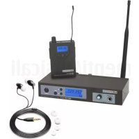
| Product type | Wireless in-ear monitoring system (transmitter + pocket receiver) |
| Brand | LD Systems |
| Model | U504.7 (band 470-490 MHz) |
| Transmission frequency range | 470 - 490 MHz |
| RF channels | 12 channels per group |
| RF groups | 1 |
| Selectable transmission power | 2 mW, 10 mW, 30 mW |
| Transmission method | FM, mono/stereo |
| Audio frequency response (transmitter) | 35 Hz - 16 kHz |
| Audio frequency response (receiver) | 40 Hz - 16 kHz |
| Signal-to-noise ratio (transmitter) | 93 dB |
| Distortion (THD+N) | < 0.3 % |
| Line inputs (transmitter) | 2 x Combo XLR/TRS 6.3 mm |
| Headphone output (receiver) | 3.5 mm stereo jack |
| Receiver battery life | Approximately 10 hours with AA batteries |
| Transmitter power supply | 12-18 V DC via power adapter |
| Receiver power supply | 2 AA 1.5 V batteries |
| Transmitter dimensions (W x H x D) | 212 x 43 x 123 mm |
| Transmitter weight | 0.66 kg (with antenna) |
| Receiver dimensions (W x H x D) | 64 x 100 x 24 mm (without antenna) |
| Receiver weight | 0.095 kg |
| Included accessories | Power adapter, BNC antenna, 19" rack mount kit, 2 AA batteries, user manual |
| Main features | Infrared synchronization, OLED display, 3-band equalizer with parametric mids, switchable limiter, 3-level squelch, panel lock, 10 user presets, mono/stereo/Focus mode |
| Maintenance and cleaning | Clean with a dry cloth. Do not open the device. Use only recommended accessories. |
| Safety | Do not expose to water or flames. Disconnect during storms. Avoid prolonged exposure to >90 dB SPL. Use at a maximum altitude of 2000 m. |
| Repairability | Contains no user-serviceable parts. Refer servicing to qualified personnel. |
Frequently Asked Questions - U504.7 LD Systems
User questions about U504.7 LD Systems
0 question about this device. Answer the ones you know or ask your own.
Ask a new question about this device
Download the instructions for your Earplug in PDF format for free! Find your manual U504.7 - LD Systems and take your electronic device back in hand. On this page are published all the documents necessary for the use of your device. U504.7 by LD Systems.
USER MANUAL U504.7 LD Systems
SAFETY INSTRUCTIONS 3
INTRODUCTION 5
CONNECTIONS, OPERATING AND DISPLAY ELEMENTS 5
TRANSMITTER 5
POCKET RECEIVER 7
MANUFACTURER'S DECLARATIONS 19
DEUTSCH
We have designed this product to operate reliably over many years. LD Systems stands for this with its name and many years of experience as a manufacturer of high-quality audio products. Please read this User's Manual carefully, so that you can begin making optimum use of your LD Systems product quickly.
You can find more information about LD-SYSTEMS at our Internet site WWW.LD-SYSTEMS.COM
SAFETY INFORMATION
- Please read these instructions carefully.
- Keep all information and instructions in a safe place.
- Follow the instructions.
- Observe all safety warnings. Never remove safety warnings or other information from the equipment.
- Use the equipment only in the intended manner and for the intended purpose.
- Use only sufficiently stable and compatible stands and/or mounts (for fixed installations). Make certain that wall mounts are properly installed and secured. Make certain that the equipment is installed securely and cannot fall down.
- During installation, observ e the applicable safety regulations for your country.
- Never install and operate the equipment near radiators, heat registers, ovens or other sources of heat. Make certain that the equipment
is always installed so that is cooled sufficiently and cannot overheat. - Never place sources of ignition, e.g., burning candles, on the equipment.
- Ventilation slits must not be blocked.
- Keep a minimum distance of 20 cm around and above the device.
- Do not use this equipment in the immediate vicinity of water (does not apply to special outdoor equipment - in this case, observe the special instructions noted below. Do not expose this equipment to flammable materials, fluids or gases. Avoid direct sunlight!
- Make certain that dripping or splashed water cannot enter the equipment. Do not place containers filled with liquids, such as vases or drinking vessels, on the equipment.
- Make certain that objects cannot fall into the device.
- Use this equipment only with the accessories recommended and intended by the manufacturer.
- Do not open or modify this equipment.
- After connecting the equipment, check all cables in order to prevent damage or accidents, e.g., due to tripping hazards.
- During transport, make certain that the equipment cannot fall down and possibly cause property damage and personal injuries.
- If your equipment is no longer functioning properly, if fluids or objects have gotten inside the equipment or if it has been damaged in anot her way, switch it off immediately and unplug it from the mains outlet (if it is a powered device). This equipment may only be repaired by authorized, qualified personnel.
- Clean the equipment using a dry cloth.
- Comply with all applicable disposal laws in your country. During disposal of packaging, please separate plastic and paper/cardboard.
- Plastic bags must be kept out of reach of children.
- Please note that changes or modifications not expressly approved by the party responsible for compliance could void the user's authority to operate the equipment.
FOR EQUIPMENT THAT CONNECTS TO THE POWER MAINS
- CAUTION: If the power cord of the device is equipped with an earthing contact, then it must be connected to an outlet with a protective ground. Never deactivate the protective ground of a power cord.
- If the equipment has been exposed to strong fluctuations in temperature (for example, after transport), do not switch it on immediately. Moisture and condensation could damage the equipment. Do not switch on the equipment until it has reached room temperature.
- Before connecting the equipment to the power outlet, first verify that the mains voltage and frequency match the values specified on the equipment. If the equipment has a voltage selection switch, connect the equipment to the power outlet only if the equipment values and the mains power values match. If the included power cord or power adapter does not fit in your wall outlet, contact your electrician.
- Do not step on the power cord. Make certain that the power cable does not become kinked, especially at the mains outlet and/or power adapter and the equipment connector.
- When connecting the equipment, make certain that the power cord or power adapter is always freely accessible. Always disconnect the equipment from the power supply if the equipment is not in use or if you want to clean the equipment. Always unplug the power cord and power adapter from the power outlet at the plug or adapter and not by pulling on the cord. Never touch the power cord and power adapter with wet hands.
- Whenever possible, avoid switching the equipment on and off in quick succession because otherwise this can shorten the useful life of the equipment.
- IMPORTANT INFORMATION: Replace fuses only with fuses of the same type and rating. If a fuse blows repeatedly, please contact an authorised service centre.
- To disconnect the equipment from the power mains completely, unplug the power cord or power adapter from the power outlet.
- If your device is equipped with a Volex power connector, the mating Volex equipment connector must be unlocked before it can be removed. However, this also means that the equipment can slide and fall down if the power cable is pulled, which can lead to personal injuries and/or other damage. For this reason, always be careful when laying cables.
- Unplug the power cord and power adapter from the power outlet if there is a risk of a lightning strike or before extended periods of disuse.
-
The appliance is not to be used by persons (including children) with reduced physical, sensory or mental capabilities, or lack of experience and knowledge.
-
Children must be instructed not to play with the device.
-
If the power cord of the device is damaged, do not use the device. The power cord must be replaced by an adequate cable or assembly from an authorized service center.

CAUTION:
To reduce the risk of electric shock, do not remove cover (or back). There are no user serviceable parts inside. Maintenance and repairs should be exclusively carried out by qualified service personnel.
The warning triangle with lightning symbol indicates dangerous uninsulated voltage inside the unit, which may cause an electrical shock.

The warning triangle with exclamation mark indicates important operating and maintenance instructions.

Warning! This device is designed for use below 2000 metres in altitude.

Warning! This product is not intended for use in tropical climates.
CAUTION! HIGH VOLUMES IN AUDIO PRODUCTS!
This device is meant for professional use. Therefore, commercial use of this equipment is subject to the respectively applicable national accident prevention rules and regulations. As a manufacturer, Adam Hall is obligated to notify you formally about the existence of potential health risks.
Hearing damage due to high volume and prolonged exposure: When in use, this product is capable of producing high sound-pressure levels (SPL) that can lead to irreversible hearing damage in performers, employees, and audience members. For this reason, avoid prolonged exposure to volumes in excess of 90 dB.
NOTE: This equipment has been tested and found to comply with the limits for a Class B digital device, pursuant to Part 15 of the FCC Rules. These limits are designed to provide reasonable protection against harmful interference in a residential installation. This equipment
generates, uses and can radiate radio frequency energy and, if not installed and used in accordance with the instructions, may cause harmful interference to radio communications. However, there is no guarantee that interference will not occur in a particular installation. If this equipment does cause harmful interference to radio or television reception, which can be determined by turning the equipment off and on, the user is encouraged to try to correct the interference by one or more of the following measures:
- Reorient or relocate the receiving antenna.
- Increase the separation between the equipment and receiver.
- Connect the equipment into an outlet on a circuit different from that to which the receiver is connected.
- Consult the dealer or an experienced radio/TV technician for help.
INTRODUCTION
Unlimited freedom of movement on the stage and always perfect monitor sound directly in your ear – this is why we developed the wireless U500 in-ear monitoring systems in Germany. Their clear, modern design and easy operation make them the perfect choice, and not just for beginners. The reliable radio transmission and the low-frequency response of 40 Hz to 16 kHz ensure professional performance. U500 in-ear sets are available in five frequency bands.
LDU5047IEM - In-Ear Monitoring-System 470 - 490 MHz
LDU5051IEM - In-Ear Monitoring-System 514 - 542 MHz
LDU505IEM - In-Ear Monitoring-System 584 - 608 MHz
LDU506IEM - In-Ear Monitoring-System 655 - 679 MHz
LDU508IEM - In-Ear Monitoring-System 823 - 832 MHz + 863 - 865 MHz
- Reliable in-ear monitoring with over 100 m range
• 96 channels to choose from - 2,10 or 30 mW ERP selectable transmit power
- Convenient infrared synchronisation
- User name and memory input for 10 custom presets
- wide frequency response
• 3-band EQ with parametric mids - Switchable limiter
• Operation in stereo or mono mode - Direct monitoring via headphone output on transmitter
- Bodypack with three-stage switchable squelch
- 10-hour bodypack operating time with two AA batteries
- Up to 12 systems can be used simultaneously
- U500 IEM transmitter compatible with U300 IEM bodypacks
LDU50XIEM includes
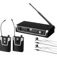
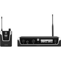
transmitter, BNC antenna, pocket receiver, receiver antenna, mains adapter, 2x AA batteries, 19-inch rack mounting kit, user manual
LDU50xIEMHP includes
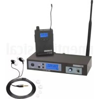
transmitter, BNC antenna, pocket receiver, receiver antenna, stereo-in-ear earphone, power adapter, 2x AA batteries, 19-inch rack mount kit, user manual
Please note
The use of the wireless microphone system may require a license, depending on the country of use. For detailed information please contact the relevant authority in your country.
CONNECTIONS, OPERATING AND DISPLAY ELEMENTS
TRANSMITTER
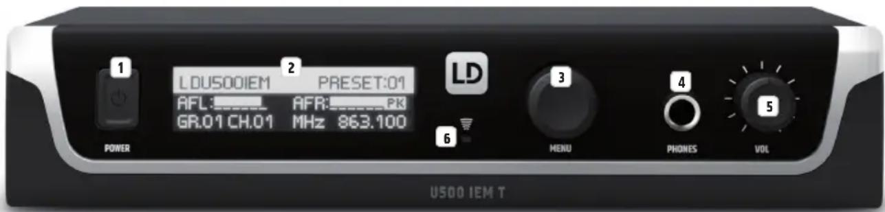
1 POWER
On/off switch. Press and hold the button for approximately 1 second to turn the device on or off. Press the button briefly (!) to go directly from the editing menu to the main display.
2 OLED DISPLAY
Multifunctional OLED graphic display for displaying the transmission frequency, frequency group and channel, individual user name, preset number and audio level for the left and right input channels on the main display. The menu items, sub-menu items and corresponding editing options are displayed in the editing menu.
3 MENU
Rotary-push encoder for navigating in the editing menu and for adjusting system settings and changing values in the corresponding menu items. Starting from the main display, the overall volume can be adjusted directly by turning the rotary-push encoder.
4 HEADPHONES
Headphone output with 6.3 mm stereo jack socket for controlling the audio signal directly at the transmitter. The headphone output signal is routed before the MONO/STEREO circuit and after INPUT GAIN, LIMITER and EQUALIZER. There is a high pass filter in the headphone output signal path.
5 VOL
Volume control for the integrated HEADPHONE output.

Infrared interface for synchronising the relevant system settings of the receiver with the transmitter (e.g. radio frequency).
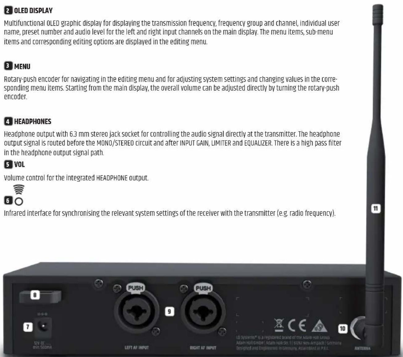
7 DC SOCKET
Low-voltage socket for the power supply of the device (12V DC 500mA, plus internal). Please use only the mains adapter supplied.
CABLE STRAIN-RELIEF
Use the strain relief for the flexible cable of the mains adapter to protect the transmitter's
low-voltage socket and the mains adapter's low voltage plug from accidental damage, and also avoid unintentional removal of the plug.
9 AF INPUT LEFT / RIGHT
Balanced line inputs left and right with XLR / 6.3 mm jack combo sockets.
10 ANTENNA
BNC connection for the supplied transmitter antenna.
11 TRANSMITTER ANTENNA
Transmitter antenna with BNC connection.
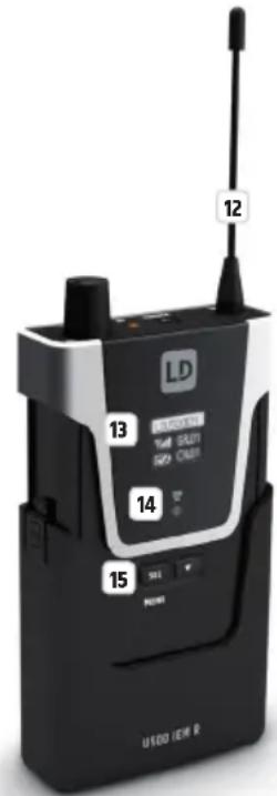
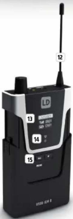
POCKET RECEIVER
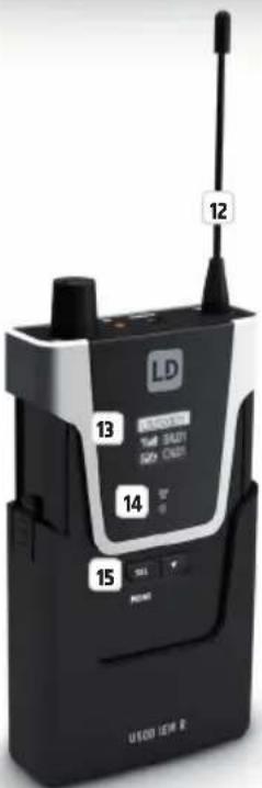
12 ANTENNA
Removable antenna of the pocket receiver. For optimum reception, do not cover or kink. Make sure that the antenna is firmly connected to the receiver during operation (hand-tighten the antenna's screw thread without tools).
13 OLED DISPLAY
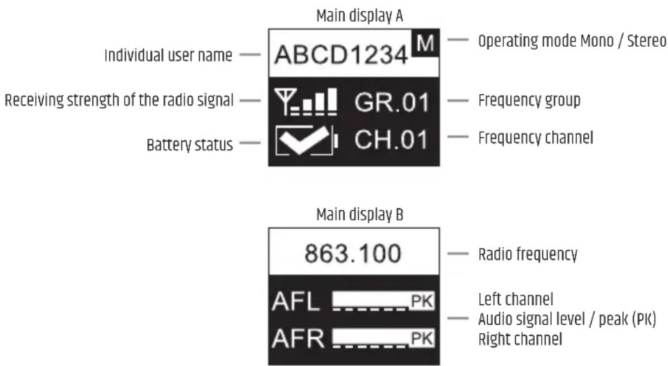
Multifunctional OLED graphic display for displaying the frequency group and the radio channel, the individual user name, the reception strength and the battery status as well as the audio level for the left and right channel. The menu items, sub-menu items and corresponding editing options are displayed in the editing menu.

Infrared interface for synchronising the relevant system settings of the receiver with the transmitter (e.g. radio frequency).
15 MENU / SEL AND
Control key for navigating in the editing menu, adjusting system settings and changing values in the corresponding menu items. To make the keys accessible for operation, press the two markers on the sides of the battery compartment cover and pull it down from the housing until it stops.
16 ANTENNA CONNECTION
Antenna connection with screw thread.
17 HEADPHONES
3.5 mm stereo jack socket for connecting earphones or headphones.
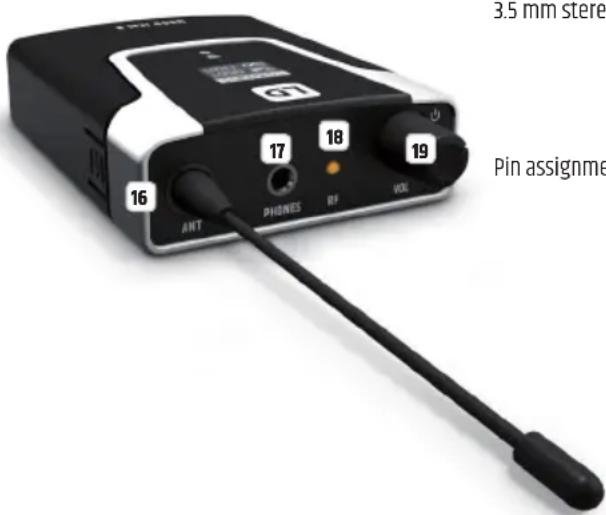

18 RF
The RF indicator LED lights up when a radio signal is available. If the LED does not light up during operation, check whether the radio channel of the receiver matches the radio channel of the transmitter or reduce the distance between receiver and transmitter.
19 ON / OFF - VOL
Turn the volume control clockwise over the snap-in point to turn on the receiver and further to the right to increase the volume. Turn the knob anticlockwise to decrease the volume and over the snap-in point to turn off the receiver. Always keep the volume at a comfortable level to avoid hearing damage.
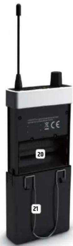
20 BATTERY COMPARTMENT
To replace the batteries, open the battery compartment of the pocket receiver by simultaneously pressing both markers on the sides of the battery cover and pulling it downwards from the housing as far as it will go. Remove the used batteries and replace with new batteries (2x AA/LR6, alkaline), following the diagram in the battery compartment. Now slide the battery compartment cover back onto the housing until it clicks into place. If you do not use the receiver for a long time, remove the batteries to prevent damage to the receiver from leaking batteries.
21 BELT CLIP
On the back of the pocket receiver there is a belt clip that can be used to attach the receiver to a trouser waistband, belt or similar.
To establish a radio connection between transmitter and receiver, the frequency group and channel or radio frequency of both devices must match. When putting the wireless transmission system into operation, be sure to position the receiver in the direct line of sight of the transmitter.
MAIN DISPLAY
After switching on the transmitter, the greeting "Welcome" is displayed briefly. The main display then appears with the following information: individual user name, preset number, level of the audio input signals with peak display, frequency group and channel (GR.xx and CH.xx) and the current radio frequency in MHz.

VOLUME
Starting from the main display, the overall volume can be adjusted directly by turning the rotary-push encoder MENU from 00 to 50. The display changes automatically to the corresponding display when the encoder is turned. After about 3 seconds of inactivity, the main display is automatically restored; pressing the encoder switches to the main display immediately.

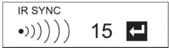
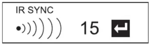
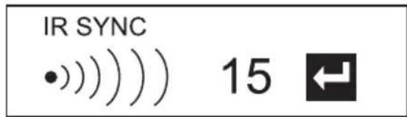
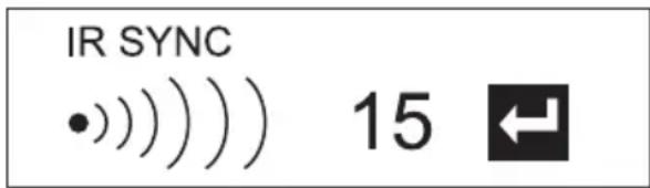
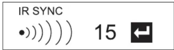
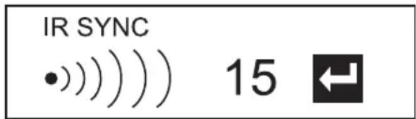
INFRARED SYNCHRONISATION (IR SYNC RUN)
To synchronise the pocket receiver with the radio frequency set in the transmitter and the individual user name, bring the infrared interface of the receiver into direct visual contact with the infrared interface of the transmitter (distance approx. 10 cm) and switch on the receiver. Now press the rotary-push encoder of the transmitter (MENU) to enter the main menu and select IR SYNC RUN (highlighted) by turning the encoder. Press MENU again to start the synchronisation process. After a few seconds the process is completed and the display of the receiver changes for a short time to "IR SYNC √", thereby confirming successful synchronisation. To cancel the operation, press MENU. Briefly (!) press POWER to return directly to the main display; after about 12 seconds of inactivity the main display will appear automatically. Please note: Direct sunlight can interfere with the synchronisation process.
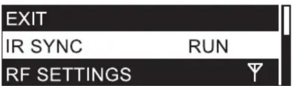
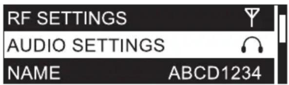
RADIO UNIT CONFIGURATION (RF SETTINGS)
Press the transmitter's rotary-push encoder (MENU) to enter the main menu, then turn the encoder to select RF SETTINGS (highlighted). Press the encoder again to enter the sub-menu and select the desired sub-menu item by turning the encoder, then confirm by pressing the encoder. If you change a value by turning the encoder, confirm the value change by pressing the encoder. The sub-menu items and the corresponding information can be found in the following table. Briefly (!) press POWER to return directly to the main display; after about 12 seconds of inactivity the main display will appear automatically.

| GROUP | 01 |
| CHANNEL | 01 |
| FREQ. MAN | 863.100 |
| RF POWER | 10mW |
| EXIT RF SETT. |
| RF SETTINGS (change value = turn encoder, confirm value change = press encoder) | ||
| GROUP U5047IEM frequency group 1U5051IEM frequency group 1U505IEM frequency groups 1 - 10U506IEM frequency groups 1 - 10U508IEM frequency groups 1 - 8 | Select group and confirm 2x | |
| CHANNEL Frequency channel 1 - 12 Select channel and confirm 2x | ||
| FREQ MAN | Set radio frequency manually | Step 1: Set frequency in 1 MHz increments and confirmStep 2: Set frequency in 25 kHz increments and confirm |
| RF POWER Set transmit power 470 - 490 MHz: 2mW / 10mW / 30mW | 514 - 542 MHz: 2mW / 10mW / 30mW584 - 608 MHz: 2mW / 10mW / 30mW655 - 679 MHz: 2mW / 10mW / 30mW823 - 832 MHz: 2mW / 10mW / 30mW, 863 - 865 MHz: 2mW / 10mW | |
| EXIT RF SETT. Exit sub-menu (press encoder) | ||
Information about transmit power and squelch setting in the bodypack receiver:
Select a low transmit power if the transmitter and receiver are in close proximity to each other; the squelch in the receiver should also be set to a low level as a guide. For greater distances between transmitter and receiver, select a higher transmit power and adjust the squelch in the receiver accordingly. For more information on setting the squelch, refer to the "SQUELCH SETTING" section under "POCKET RECEIVER OPERATION" in this manual. In any case, make sure that the transmitter and receiver have direct eye contact and that no obstacles between the transmitter and receiver can interfere with radio operation.
Depending on the situation, different settings may be required for trouble-free operation. Please note that when other transmitters are used in the vicinity this increases interference that may cause problems with the radio connection. Selecting a different radio frequency can avoid interference in this case.
CAUTION! BEFORE adjusting the squelch, make sure that the receiver volume is set to the lowest possible level, as changing the squelch threshold may cause loud background noise that can potentially inflict hearing damage as well as damage to connected headphones or earphones.
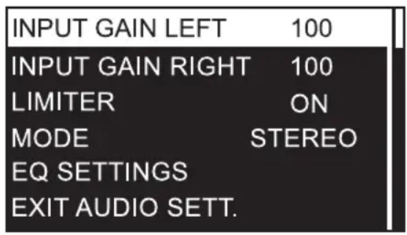
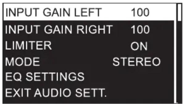
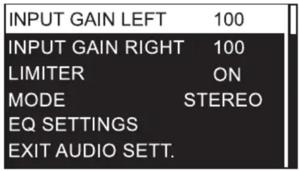
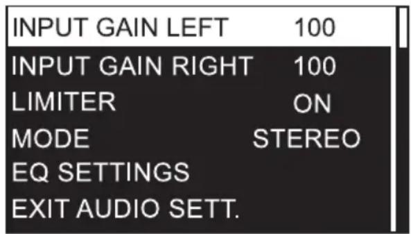
AUDIO SETTINGS
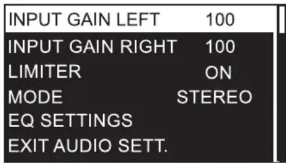
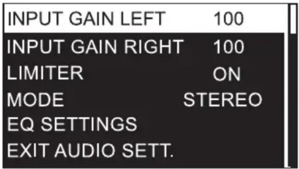
Press the transmitter's rotary-push encoder (MENU) to enter the main menu, then turn the encoder to select AUDIO SETTINGS (highlighted). Press the encoder again to enter the sub-menu and select the desired sub-menu item by turning the encoder. Confirm your entry by pressing the encoder. If you change a value by turning the encoder, confirm the value change by pressing the encoder. The sub-menu items and the corresponding information can be found in the following table. Briefly (!) press POWER to return directly to the main display; after about 12 seconds of inactivity the main display will appear automatically.
| AUDIO SETTINGS (change value = turn encoder, confirm value change = press encoder) | |||
| INPUT GAIN LEFT | Input gain left channel | 000 - 100 | For an optimum signal-to-noise ratio, set the signals left and right as high as possible, but make sure the PEAK indicator does not appear in the display, or only briefly, in order to avoid signal distortion. Adjust the output level of the playback device if necessary. |
| INPUT GAIN RIGHT input gain | right channel 000 - 100 | ||
| LIMITER | Activate / deactivate input limiter | ON = enabled (recommended)OFF = disabled | |
| MODE Setting the operating mode to Mono / StereoThe selected operating mode is shown in the display of the receiver (M = Mono, S = Stereo) | MONO = Input signals left and right are summed to a mono signal.Shift the signal to the left or right on the receiver (BALANCE).STEREO = playback of the input signal in stereo. Setting the balance on the receiver (BALANCE)Activate the STEREO mode in the transmitter even if you want to use the FOCUS mode in the pocket receiver. | ||
| EQ SETTINGS | BASS EQ | G: +/- 15dB | Bass frequency gain from -15dB to +15dB |
| f: 60Hz / 80Hz / 100Hz / 200Hz Setting the bass frequency | |||
| MIDDLE EQ G: | +/- 15dB Centre frequency gain from -15dB to +15dB | ||
| f: 500Hz / 1000Hz / 1500Hz / 2500Hz | Setting the centre frequency | ||
| Q: 0.50 / 0.75 / 1.00 / 1.25 Setting the Q-factor | |||
| TREBLE EQ G: | +/- 15dB Treble frequency gain from -15dB to +15dB | ||
| f: 10.0kHz / 12.5kHz / 15.0kHz / 17.5kHz | Setting the treble frequency | ||
| EXIT EQ SETT. | Exit equalizer menu (press encoder) | ||
| EXIT AUDIO SETT. Exit sub-menu (press encoder) | |||
INDIVIDUAL USERNAME (NAME)
Press the transmitter's rotary-push encoder (MENU) to enter the main menu, then turn the encoder to select NAME (highlighted) and press the encoder to confirm. Now set the individual name (up to 8 digits) by turning the encoder to select a letter, character or number for the first digit of the name and confirm by pressing the encoder. This is followed by the input for the second digit and so on. Once the name is complete, press the encoder again to confirm. Briefly (!) press POWER to return directly to the main display; after about 12 seconds of inactivity the main display will appear automatically.


Press the transmitter's rotary-push encoder (MENU) to enter the main menu, then turn the encoder to select BRIGHTNESS (highlighted) and press the encoder to confirm. Select the 3-step display brightness (HIGH = high, MID = medium, LOW = low) by turning the encoder as desired and press 2x on the encoder to confirm. Briefly (!) press POWER to return directly to the main display; after about 12 seconds of inactivity the main display will appear automatically.


Press the transmitter's rotary-push encoder (MENU) to enter the main menu, then turn the encoder to select PANEL LOCK (highlighted) and press the encoder to confirm. To lock the control elements, select ON by turning the encoder and press the encoder twice to confirm. Briefly (!) press POWER to return directly to the main display; after about 10 seconds of inactivity the main display will appear automatically. If one of the POWER controls or the MENU rotary-push encoder is pressed, "PANEL LOCK ON" briefly appears on the display and setting changes are blocked. To unlock the controls, press and hold the rotary-push encoder for about 2 seconds and select OFF in the PANEL LOCK menu item to permanently allow operation using the controls.


SAVE PRESET
Settings under RF SETTINGS, AUDIO SETTINGS and the individual name can be stored in up to 10 different presets. Once you have made the appropriate settings, press the transmitter's rotary-push encoder (MENU) to enter the main menu, then turn the encoder to select SAVE PRESET (highlighted) and press the encoder to confirm. Now select the preset number you want to use for saving by turning the encoder (01 - 10), confirm by pressing the encoder, then select YES by turning the encoder and confirm by pressing the encoder twice. If you want to cancel the process, select NO and likewise confirm. Briefly (!) press POWER to return directly to the main display; after about 12 seconds of inactivity the main display will appear automatically.


LOAD PRESET
Press the transmitter's rotary-push encoder (MENU) to enter the main menu, then turn the encoder to select LOAD PRESET (highlighted) and press the encoder to confirm. Now select the preset number you want to load by turning the encoder (01 - 10), confirm by pressing the encoder, then select YES by turning the encoder and confirm by pressing the encoder twice. If you want to cancel the process, select NO and likewise confirm. Briefly (!) press POWER to return directly to the main display; after about 12 seconds of inactivity the main display will appear automatically.


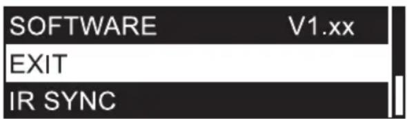
VIEW SOFTWARE VERSION (SOFTWARE)
Press the rotary-push encoder of the transmitter (MENU) to enter the main menu and then select SOFTWARE (highlighted) by turning the encoder. Briefly (!) press POWER to return directly to the main display; after about 12 seconds of inactivity the main display will appear automatically.

LEAVE MAIN MENU (EXIT)
To leave the main menu and return to the main display, select EXIT (highlighted) by turning the rotary-push encoder and press the encoder. Briefly (!) press POWER to return directly to the main display; after about 12 seconds of inactivity the main display will appear automatically.
To establish a radio connection between transmitter and receiver, the channel group and channel number or the radio frequency of the two devices must match.
When putting the wireless transmission system into operation, be sure to position the receiver in direct line of sight with the transmitter.
MAIN DISPLAY
Shortly after switching on the pocket receiver, the main display A appears with the following information: Individual user name, operating mode, radio signal reception strength, battery status, frequency group and channel.
Alternatively, the main display B is shown with the radio frequency in MHz and the level of the left and right audio signal with peak display (PK).
Briefly press the ▼ button to switch between the two display variants.
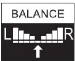
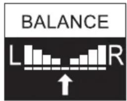
SET VOLUME BALANCE (BALANCE / FADER)
MONO mode: Activate MONO mode in the transmitter. The two channels left and right are mono summed. In the receiver, the mono signal can be shifted to the left or right in BALANCE. Press SEL (MENU) for about 2 seconds to enter the main menu, then, if not already selected, press SEL repeatedly to select BALANCE (highlighted) and press ▼ to confirm. Now move the signal to the left or right as desired by pressing ▼ (repeatedly if necessary). To exit, press SEL, select EXIT again by pressing SEL and press ▼ to confirm. The main display will automatically appear after approximately 5 seconds of inactivity.
STEREO mode: Activate STEREO mode in the transmitter. A stereo signal available to the transmitter is also reproduced in stereo in the pocket receiver (deactivate FOCUS mode - FOCUS OFF). In the receiver, the balance between the left and right channel can be set in the menu item BALANCE. Press SEL (MENU) for about 2 seconds to enter the main menu, then, if not already selected, press SEL repeatedly to select BALANCE (highlighted) and press ▼ to confirm. Now adjust the balance as desired by pressing ▼ (repeatedly if necessary). To exit, press SEL, select EXIT by pressing SEL again and press ▼ to confirm. The main display will automatically appear after approximately 5 seconds of inactivity.

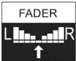
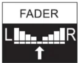
FOCUS mode: The two channels left and right are played back in the middle and the volume balance between the two channels can be adjusted directly on the pocket receiver (e.g. left channel mixer mono sum, right channel solo vocals). Activate STEREO mode in the transmitter. Press SEL (MENU) on the pocket receiver for about 2 seconds to enter the main menu, then press SEL repeatedly to select FOCUS (highlighted) and press the ▼ arrow button to confirm. Press ▼ again to activate the FOCUS ON mode. Confirm by pressing SEL and now select FADER by pressing SEL repeatedly if necessary and press ▼. Now adjust the balance as desired by pressing ▼ (repeatedly if necessary). To exit, press SEL, select EXIT by pressing SEL again and press ▼ to confirm. The main display will automatically appear after approximately 5 seconds of inactivity.


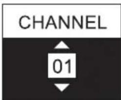
SET FREQUENCY CHANNEL (CHANNEL)
Press SEL (MENU) for about 2 seconds to enter the main menu, then press SEL repeatedly to select CHANNEL (highlighted) and press ▼ to confirm. Now select the desired frequency channel by pressing ▼ (repeated if necessary). To exit, press SEL, select EXIT again by pressing SEL and press ▼ to confirm. The main display will automatically appear after approximately 5 seconds of inactivity.

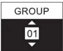
SET FREQUENCY GROUP (GROUP)
Press SEL (MENU) for about 2 seconds to enter the main menu, then press SEL repeatedly to select GROUP (highlighted) and press ▼ to confirm. Now select the desired frequency group (depending on the model) by pressing ▼ (repeated if necessary). To exit, press SEL, select EXIT again by pressing SEL and press ▼ to confirm. The main display will automatically appear after approximately 5 seconds of inactivity.

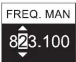
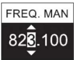
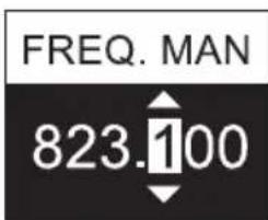
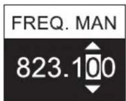
MANUALLY SET THE RADIO FREQUENCY (FREQ. MAN.)
Press SEL (MENU) for about 2 seconds to enter the main menu, then press SEL repeatedly to select FREQ. MAN. (highlighted) and press ▼ to confirm. Now select the radio frequency range below 820, 830 or 860 MHz by pressing ▼ (repeatedly if necessary) and press SEL again to set the frequency in 1 MHz increments using ▼. Then press SEL to adjust the radio frequency in 100kHz increments by pressing ▼ and press SEL again to adjust the radio frequency in 25kHz increments. To exit, press SEL, select EXIT again by pressing SEL and press ▼ to confirm. The main display will automatically appear after approximately 5 seconds of inactivity.

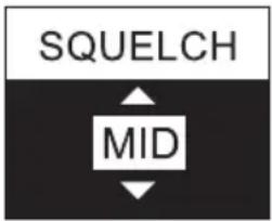
ADJUST NOISE BARRIER (SQUELCH)
The 3-stage squelch prevents unwanted noise when the transmitter is off. In addition, sudden noise is suppressed if the signal transmitted from the transmitter to the receiver is not strong enough (e.g. due to the distance being too great). CAUTION! BEFORE adjusting the squelch, make sure that the receiver volume is set to the lowest possible level, as changing the squelch threshold may cause loud background noise that can potentially inflict hearing damage as well as damage to connected headphones or earphones. Set the squelch (when the transmitter is off) to the lowest setting where ambient noise is still effectively suppressed (LOW / MID / HI). In the "HI" setting, the transmission range may be reduced under unfavourable circumstances. Press SEL (MENU) for about 2 seconds to enter the main menu, then press SEL repeatedly to select SQUELCH (highlighted) and press ▼ to confirm. Now select the desired setting by pressing ▼ (repeatedly if necessary). To exit, press SEL, select EXIT again by pressing SEL and press ▼ to confirm. The main display will automatically appear after approximately 5 seconds of inactivity.

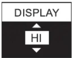
SET DISPLAY BRIGHTNESS (DISPLAY)
Press SEL (MENU) for about 2 seconds to enter the main menu, then press SEL repeatedly to select DISPLAY (highlighted) and press ▼ to confirm. Now select the desired setting by pressing ▼ (repeatedly if necessary) (HI = brightness high / LOW = brightness low). To exit, press SEL, select EXIT again by pressing SEL (repeatedly if necessary) and press ▼ to confirm. The main display will automatically appear after approximately 5 seconds of inactivity.

LEAVE MAIN MENU (EXIT)
To exit the main menu and return to the main display, select EXIT (highlighted) by pressing SEL repeatedly (highlighted) and then press ▼. After approximately 5 seconds of inactivity, the main display will appear automatically.

BATTERY STATUS
The battery charge status is shown in the display and continuously updated (main display A). 📋 appears when the batteries are fully charged, □ indicates a charge status of approx. 70% and □ indicates a charge status of approx. 30%. As soon as a critically low charge status is reached, the display changes to "LOW BATTERY" approximately every 3 seconds, the □ symbol for "low battery" appears and a pure tone at approx. 500Hz is emitted via the headphone socket as an acoustic warning signal. Replace depleted batteries immediately.

TROUBLESHOOTING
| PROBLEM DISPLAY SOLUTION | ||
| No audio signal or level too low | Receiver: Reception is not indicated by RF LED. Check if the transmitter is turned on. | |
| Receiver: Display lighting is switched off Check that the receiver is switched on and that the battery charge status is sufficient. | ||
| Receiver: Reception is not indicated by RF LED. Transmitter: Device is switched on. Audio signal is available. | Check that the radio frequency of the transmitter and receiver is the same.Check the transmit power.Reduce the distance between transmitter and receiver.Make sure that there is a direct line of sight between transmitter and receiver.Make sure that the antennas of transmitter and receiver are correctly connected, not covered and not kinked.Reduce the level of noise reduction (SQUELCH) | |
| Receiver: Reception is indicated by RF LED. Check whether an audio signal is present at the transmitter.If necessary, increase the signal level of the playback device or check the GAIN setting in the transmitter. | ||
| Distortion and interference | Receiver: Reception is indicated by RF LED. | Remove possible sources of interference (digital devices, other radio systems).Increase the level of noise reduction (SQUELCH) at the receiver. |
| Distorted sound Receiver: "LOW BATTERY" is displayed.Receiver: Peak is shown AF PK in the receiver and transmitter display. | Check the headphone output of the transmitter.Make sure that the available signal is "clean".If necessary, reduce the signal level of the playback device or lower the audio level GAIN in the transmitter. | |
RECOMMENDATIONS FOR ERROR PREVENTION
- when using a radio transmitter and a radio receiver on your body at the same time, position the two devices as far apart from each other as possible.
- Do not install the radio receiver and radio transmitter together in a rack, and position a receiver rack as far away from a transmitter rack as possible.
- When rack-mounting transmitters or receivers, maintain at least half a height unit between the two.
- Use separate power supplies for transmitter and receiver and do not use the same power supply for wireless systems made by different manufacturers.
TECHNICAL DATA
Model Number: LDU5047IEMT LDU5051IEMT LDU505IEMT LDU506IEMT LDU508IEMT
Product type: In-Ear monitoring In-Ear monitoring In-Ear monitoring In-Ear monitoring In-Ear monitoring
Type: Transmitter Transmitter Transmitter Transmitter Transmitter
Transmission frequency range: 470 - 490 MHz 514 - 542 MHz 584 - 608 MHz 655 - 679 MHz 823 - 832 MHz,
863 - 865 MHz
RF-groups: 1110108
RF-channels: 12 12 12 12 12
| Transmission method: | FM, mono/stereo | FM, mono/stereo | FM, mono/stereo | FM, mono/stereo | FM, mono/stereo |
| Rated HF output power: | 2 mW, 10 mW,30 mW | 2 mW, 10 mW,30 mW | 2 mW, 10 mW,30 mW | 2 mW, 10 mW,30 mW | 823 - 832 MHz2 mW, 10 mW,30 mW863 - 865 MHz2 mW, 10 mW |
| Antenna gain: | 2 dBi | 2 dBi | 2 dBi | 2 dBi | 2 dBi |
| Antenna connector: | BNC | BNC | BNC | BNC | BNC |
| Audio frequency response (- 3dB): | 35 Hz - 16000 Hz | 35 Hz - 16000 Hz | 35 Hz - 16000 Hz | 35 Hz - 16000 Hz | 35 Hz - 16000 Hz |
| THD+N @ 1kHz, +4dBu input signal: | < 0.3 % | < 0.3 % | < 0.3 % | < 0.3 % | < 0.3 % |
| S/N -ratio @ 1kHz, A-weighted: | 93 dB | 93 dB | 93 dB | 93 dB | 93 dB |
| Dynamic range @ 1kHz, non-weighted: | 88 dB | 88 dB | 88 dB | 88 dB | 88 dB |
| Input sensitivity: | - 9 dBu (all gain controls full, stereo mode) | - 9 dBu (all gain controls full, stereo mode) | - 9 dBu (all gain controls full, stereo mode) | - 9 dBu (all gain controls full, stereo mode) | - 9 dBu (all gain controls full, stereo mode) |
| Max. input level: | 18 dBu (gain controls set to 90, TX Volume control set to 38, stereo mode) | 18 dBu (gain controls set to 90, TX Volume control set to 38, stereo mode) | 18 dBu (gain controls set to 90, TX Volume control set to 38, stereo mode) | 18 dBu (gain controls set to 90, TX Volume control set to 38, stereo mode) | 18 dBu (gain controls set to 90, TX Volume control set to 3B, stereo mode) |
| CMRR IEC: | < 45 dB | < 45 dB | < 45 dB | < 45 dB | < 45 dB |
| Line inputs: | 2 | 2 | 2 | 2 | 2 |
| Line input connectors: | XLR (balanced)/ Combo TRS6.3 mm | XLR (balanced)/ Combo TRS6.3 mm | XLR (balanced)/ Combo TRS6.3 mm | XLR (balanced)/ Combo TRS6.3 mm | XLR (balanced)/ Combo TRS6.3 mm |
| Input impedance: | 12 kohms | 12 kohms | 12 kohms | 12 kohms | 12 kohms |
| Controls: | POWER on-off-button, MENU rotary-push-encoder, phones volume | POWER on-off-button, MENU rotary-push-encoder, phones volume | POWER on-off-button, MENU rotary-push-encoder, phones volume | POWER on-off-button, MENU rotary-push-encoder, phones volume | POWER on-off-button, MENU rotary-push-encoder, phones volume |
| Indicators: Multifunctional | OLED-display | Multifunctional OLED-display | Multifunctional OLED-display | Multifunctional OLED-display | Multifunctional OLED-display |
| Power consumption (nominal): | 3.5 W | 3.5 W | 3.5 W | 3.5 W | 3.5 W |
| Operating voltage: | 12 - 18 V DC | 12 - 18 V DC | 12 - 18 V DC | 12 - 18 V DC | 12 - 18 V DC |
| Voltage input connector: | 5.3 mm barrel jack, plus inside | 5.3 mm barrel jack, plus inside | 5.3 mm barrel jack, plus inside | 5.3 mm barrel jack, plus inside | 5.3 mm barrel jack, plus inside |
| Ambient temperature (in operation): | 0 °C - 35 °C | 0 °C - 35 °C | 0 °C - 35 °C | 0 °C - 35 °C | 0 °C - 35 °C |
| Relative humidity: | < 80 %(non-condensing) | < 80 %(non-condensing) | < 80 %(non-condensing) | < 80 %(non-condensing) | < 80 %(non-condensing) |
| Dimensions (W x H x D): | 212 x 43 x 123 mm | 212 x 43 x 123 mm | 212 x 43 x 123 mm | 212 x 43 x 123 mm | 212 x 43 x 123 mm |
| Weight: 0.66 kg(with antenna) | 0.66 kg(with antenna) | 0.66 kg(with antenna) | 0.66 kg(with antenna) | 0.66 kg(with antenna) | 0.66 kg(with antenna) |
| Accessories included: Power adapter,BNC-antenna, 19"rack mount kit | Power adapter,BNC-antenna, 19"rack mount kit | Power adapter,BNC-antenna, 19"rack mount kit | Power adapter,BNC-antenna, 19"rack mount kit | Power adapter,BNC-antenna, 19"rack mount kit | Power adapter,BNC-antenna, 19"rack mount kit |
Model Number: LDU5047IEMR LDU5051IEMR LDU505IEMR LDU506IEMR LDU508IEMR
| Product type: In-Ear monitoring In-Ear monitoring In-Ear monitoring In-Ear monitoring | |||||
| Type: Bodypack receiver, non-diversity | Bodypack receiver, non-diversity | Bodypack receiver, non-diversity | Bodypack receiver, non-diversity | Bodypack receiver, non-diversity | |
| Transmission frequency range: 470 - 490 MHz 514 - 542 MHz 584 - 608 MHz 655 - 679 MHz 823 - 832 MHz, | |||||
| RF-groups: 1110 | 10 | 8 | |||
| RF-channels: | 12 | 12 | 12 | 12 | 12 |
| Phones output: | 3.5 mm stereo jack | 3.5 mm stereo jack | 3.5 mm stereo jack | 3.5 mm stereo jack | 3.5 mm stereo jack |
| Phones minimum impedance: | 16 ohms | 16 ohms | 16 ohms | 16 ohms | 16 ohms |
| Phones max output level: | 80 mW @ 33 ohm load / 33 mW @ 16 ohm load | 80 mW @ 33 ohm load / 33 mW @ 16 ohm load | 80 mW @ 33 ohm load / 33 mW @ 16 ohm load | 80 mW @ 33 ohm load / 33 mW @ 16 ohm load | 80 mW @ 33 ohm load / 33 mW @ 16 ohm Load |
| Audio frequency response: | 40 Hz - 16000 Hz | 40 Hz - 16000 Hz | 40 Hz - 16000 Hz | 40 Hz - 16000 Hz | 40 Hz - 16000 Hz |
| L/R crosstalk 100 Hz/1 kHz/10 kHz: | 55/55/53 dB's | 55/55/53 dB's | 55/55/53 dB's | 55/55/53 dB's | 55/55/53 dB's |
| Residual noise: | 5.5 uVrms (a-weighted) | 5.5 uVrms (a-weighted) | 5.5 uVrms (a-weighted) | 5.5 uVrms (a-weighted) | 5.5 uVrms (a-weighted) |
| Antenna connector: | Threaded connector | Threaded connector | Threaded connector | Threaded connector | Threaded connector |
| Controls: | ON/OFF/VOLUME, SEL, ▼ | ON/OFF/VOLUME, SEL, ▼ | ON/OFF/VOLUME, SEL, ▼ | ON/OFF/VOLUME, SEL, ▼ | ON/OFF/VOLUME, SEL, ▼ |
| Indicators: Multifunctional | OLED-display, RF-LED | Multifunctional OLED-display, RF-LED | Multifunctional OLED-display, RF-LED | Multifunctional OLED-display, RF-LED | Multifunctional OLED-display, RF-LED |
| Power consumption (nominal): | 0.7 W | 0.7 W | 0.7 W | 0.7 W | 0.7 W |
| Operating voltage: | 2 x 1.5 V DC AA-batteries | 2 x 1.5 V DC AA-batteries | 2 x 1.5 V DC AA-batteries | 2 x 1.5 V DC AA-batteries | 2 x 1.5 V DC AA-batteries |
| Ambient temperature (in operation): | 0 °C - 35 °C | 0 °C - 35 °C | 0 °C - 35 °C | 0 °C - 35 °C | 0 °C - 35 °C |
| Relative humidity: | < 80 % (non-condensing) | < 80 % (non-condensing) | < 80 % (non-condensing) | < 80 % (non-condensing) | < 80 % (non-condensing) |
| Dimensions (W x H x D, without antenna): | 64 x 100 x 24 mm | 64 x 100 x 24 mm | 64 x 100 x 24 mm | 64 x 100 x 24 mm | 64 x 100 x 24 mm |
| Weight: | 0.095 kg | 0.095 kg | 0.095 kg | 0.095 kg | 0.095 kg |
| Accessories included: Threaded | antenna, 2x AA battery | Threaded antenna, 2x AA battery | Threaded antenna, 2x AA battery | Threaded antenna, 2x AA battery | Threaded antenna, 2x AA battery |
| Other Features: | Additional low battery indication: 500 Hz signal via headphone jack | Additional low battery indication: 500 Hz signal via headphone jack | Additional low battery indication: 500 Hz signal via headphone jack | Additional low battery indication: 500 Hz signal via headphone jack | Additional low battery indication: 500 Hz signal via headphone jack |
Model Number: LDIEHP2
| Product type: Stereo in-ear | headphones |
| Frequency response: 20 Hz - 20000 Hz | |
| Impedance: 33 ohms | |
| Audio connector: 3.5 mm stereo | plug |
| Cable: 1.27 m | (detachable) |
| Weight: 0.016 kg | |
| Accessories included: 3 pairs of silicone | ear buds, 3 pairs of foam ear buds |
MANUFACTURER'S DECLARATIONS
MANUFACTURER'S WARRANTY & LIMITATIONS OF LIABILITY
You can find our current warranty conditions and limitations of liability at: https://cdn-shop.adamhall.com/media/pdf/MANUFACTURERS-DECLARATIONS_LD_SYSTEMS.pdf To request warranty service for a product, please contact Adam Hall GmbH, Adam-Hall-Str. 1, 61267 Neu Anspach / Email: Info@adamhall.com / +49 (0)6081 / 9419-0.

CORRECT DISPOSAL OF THIS PRODUCT
(valid in the European Union and other European countries with a differentiated waste collection system)
This symbol on the product, or on its documents indicates that the device may not be treated as household waste. This is to avoid environmental damage or personal injury due to uncontrolled waste disposal. Please dispose of this product separately from other waste and have it recycled to promote sustainable economic activity. Household users should contact either the retailer where they purchased this product, or their local government office, for details on where and how they can recycle this item in an environmentally friendly manner. Business users should contact their supplier and check the terms and conditions of the purchase contract. This product should not be mixed with other commercial waste for disposal.
FCC STATEMENT
This device complies with Part 15 of the FCC Rules. Operation is subject to the following two conditions:
(1) This device may not cause harmful interference, and
(2) This device must accept any interference received, including interference that may cause undesired operation
CE Compliance
Adam Hall GmbH states that this product meets the following guidelines (where applicable):
R&TTE (1999/5/EC) or RED (2014/53/EU) from June 2017
Low voltage directive (2014/35/EU)
EMV directive (2014/30/EU)
RoHS (2011/65/EU)
The complete declaration of conformity can be found at www.adamhall.com.
Furthermore, you may also direct your enquiry to info@adamhall.com.
EU DECLARATION OF CONFORMITY
Hereby, Adam Hall GmbH declares that this radio equipment type is in compliance with Directive 2014/53/EU.
The full text of the EU declaration of conformity is available at the following
internet address: www.adamhall.com/compliance/
DEUTSCH
BEDIENUNG SENDER
INFRAROT SYNCHRONISATION (IR SYNC RUN)
KONFIGURATION DER FUNKEINHEIT (RF SETTINGS)
| GROUP | 01 |
| CHANNEL | 01 |
| FREQ. MAN | 863.100 |
| RF POWER | 10mW |
| EXIT RF SETT. |
DISPLAY-HELLIGKEIT EINSTELLEN (BRIGHTNESS)
HAUPTMENÜ VERLASSEN (EXIT)
HAUPTMENÜ VERLASSEN (EXIT)
APPAREILS RELIÉS AU SECTEUR
RÉCEPTEUR DE POCHE
12 ANTENNE
SYNCHRONISATION PAR INFRAROUGE (IR SYNC RUN)
CONFIGURATION DE L'UNITÉ RADIO (RF SETTINGS)
| GROUP | 01 |
| CHANNEL | 01 |
| FREQ. MAN | 863.100 |
| RF POWER | 10mW |
| EXIT RF SETT. |
RÉGLAGE DE LA LUMINOSITÉ DE L'ÉCRAN (BRIGHTNESS)
QUITTER LE MENU PRINCIPAL (EXIT)
QUITTER LE MENU PRINCIPAL (EXIT)
(Valid in the European Union and other European countries with waste separation)
DÉCLARATION DE CONFORMITÉ CE
18 RF
| GROUP | 01 |
| CHANNEL | 01 |
| FREQ. MAN | 863.100 |
| RF POWER | 10mW |
| EXIT RF SETT. |
AJUSTE DEL BRILLO DE PANTALLA (BRIGHTNESS)
SALIR DEL MENÚ PRINCIPAL (EXIT)
MANEJO DEL RECEPTOR DE PETACA
SALIR DEL MENÚ PRINCIPAL (EXIT)
BÚSQUEDA DE ERRORES
OBSŁUGA NADAJNIKA
SYNCHRONIZACJA PODCZERWIENI (IR SYNC RUN)
KONFIGURACJA ŁĄCZNOŚCI RADIOWEJ (RF SETTINGS)
| GROUP | 01 |
| CHANNEL | 01 |
| FREQ. MAN | 863.100 |
| RF POWER | 10mW |
| EXIT RF SETT. |
USTAWIANIE JASNOŚCI EKRANU (BRIGHTNESS)
WYJŚCIE Z MENU GŁÓWNEGO (EXIT)
DEKLARACJA ZGODNOŚCI WE
RICEVITORE PORTATILE
12 ANTENNA
15 MENU / SEL UND

SINCRONIZZAZIONE A INFRAROSSI (IR SYNC RUN)
CONFIGURAZIONE DELL'UNITÀ RADIO (RF SETTINGS)
| GROUP | 01 |
| CHANNEL | 01 |
| FREQ. MAN | 863.100 |
| RF POWER | 10mW |
| EXIT RF SETT. |
IMPOSTAZIONE DELLA LUMINOSITÀ DEL DISPLAY (BRIGHTNESS)
USCITA DAL MENU PRINCIPALE (EXIT)
USO DEL RICEVITORE PORTATILE


IMPOSTAZIONE DEL CANALE DI FREQUENZA (CHANNEL)
USCITA DAL MENU PRINCIPALE (EXIT)

- DEUTSCH
- SAFETY INFORMATION
- FOR EQUIPMENT THAT CONNECTS TO THE POWER MAINS
- CAUTION
- CAUTION! HIGH VOLUMES IN AUDIO PRODUCTS
- INTRODUCTION
- LDU50XIEM INCLUDES
- LDU50XIEMHP INCLUDES
- PLEASE NOTE
- CONNECTIONS, OPERATING AND DISPLAY ELEMENTS
- TRANSMITTER
- 1 POWER
- 2 OLED DISPLAY
- 3 MENU
- 4 HEADPHONES
- 5 VOL
- 7 DC SOCKET
- CABLE STRAIN-RELIEF
- 9 AF INPUT LEFT / RIGHT
- 10 ANTENNA
- 11 TRANSMITTER ANTENNA
- POCKET RECEIVER
- 12 ANTENNA
- 13 OLED DISPLAY
- 15 MENU / SEL AND
- 16 ANTENNA CONNECTION
- 17 HEADPHONES
- 18 RF
- 19 ON / OFF - VOL
- 20 BATTERY COMPARTMENT
- 21 BELT CLIP
- MAIN DISPLAY
- VOLUME
- INFRARED SYNCHRONISATION (IR SYNC RUN)
- RADIO UNIT CONFIGURATION (RF SETTINGS)
- INFORMATION ABOUT TRANSMIT POWER AND SQUELCH SETTING IN THE BODYPACK RECEIVER
- AUDIO SETTINGS
- INDIVIDUAL USERNAME (NAME)
- SAVE PRESET
- LOAD PRESET
- VIEW SOFTWARE VERSION (SOFTWARE)
- LEAVE MAIN MENU (EXIT)
- SET VOLUME BALANCE (BALANCE / FADER)
- SET FREQUENCY CHANNEL (CHANNEL)
- SET FREQUENCY GROUP (GROUP)
- MANUALLY SET THE RADIO FREQUENCY (FREQ. MAN.)
- ADJUST NOISE BARRIER (SQUELCH)
- SET DISPLAY BRIGHTNESS (DISPLAY)
- BATTERY STATUS
- RECOMMENDATIONS FOR ERROR PREVENTION
- TECHNICAL DATA
- MANUFACTURER'S DECLARATIONS
- MANUFACTURER'S WARRANTY & LIMITATIONS OF LIABILITY
- CORRECT DISPOSAL OF THIS PRODUCT
- FCC STATEMENT
- CE COMPLIANCE
- EU DECLARATION OF CONFORMITY
- BEDIENUNG SENDER
- INFRAROT SYNCHRONISATION (IR SYNC RUN)
- KONFIGURATION DER FUNKEINHEIT (RF SETTINGS)
- DISPLAY-HELLIGKEIT EINSTELLEN (BRIGHTNESS)
- HAUPTMENÜ VERLASSEN (EXIT)
- APPAREILS RELIÉS AU SECTEUR
- RÉCEPTEUR DE POCHE
- 12 ANTENNE
- SYNCHRONISATION PAR INFRAROUGE (IR SYNC RUN)
- CONFIGURATION DE L'UNITÉ RADIO (RF SETTINGS)
- RÉGLAGE DE LA LUMINOSITÉ DE L'ÉCRAN (BRIGHTNESS)
- QUITTER LE MENU PRINCIPAL (EXIT)
- DÉCLARATION DE CONFORMITÉ CE
- AJUSTE DEL BRILLO DE PANTALLA (BRIGHTNESS)
- SALIR DEL MENÚ PRINCIPAL (EXIT)
- MANEJO DEL RECEPTOR DE PETACA
- OBSŁUGA NADAJNIKA
- SYNCHRONIZACJA PODCZERWIENI (IR SYNC RUN)
- KONFIGURACJA ŁĄCZNOŚCI RADIOWEJ (RF SETTINGS)
- USTAWIANIE JASNOŚCI EKRANU (BRIGHTNESS)
- WYJŚCIE Z MENU GŁÓWNEGO (EXIT)
- DEKLARACJA ZGODNOŚCI WE
- RICEVITORE PORTATILE
- 15 MENU / SEL UND
- SINCRONIZZAZIONE A INFRAROSSI (IR SYNC RUN)
- CONFIGURAZIONE DELL'UNITÀ RADIO (RF SETTINGS)
- IMPOSTAZIONE DELLA LUMINOSITÀ DEL DISPLAY (BRIGHTNESS)
- USCITA DAL MENU PRINCIPALE (EXIT)
- USO DEL RICEVITORE PORTATILE
- IMPOSTAZIONE DEL CANALE DI FREQUENZA (CHANNEL)
Brand : LD Systems
Model : U504.7
Category : Earplug