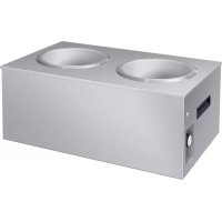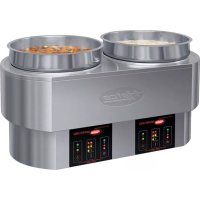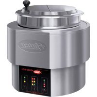
SW211QT - Kettle Hatco - Free user manual and instructions
Find the device manual for free SW211QT Hatco in PDF.


| Product Type | Electric Hot Food Well |
| Brand | Hatco |
| Model | SW211QT |
| Supply Voltage | 120–240 V (depending on model) |
| Power | 500–1650 W (depending on configuration) |
| Phase | 1 |
| Weight | 4–14 kg depending on model |
| Dimensions (approx.) | Variable, e.g., 347×553×263 mm (model HWB-FUL) |
| Main Material | Stainless steel and aluminized steel |
| Well Capacity | 4, 7, or 11 quarts (round); large size up to 20.75" x 12.75" |
| Usage | Dry or with water |
| Auto-Fill | Optional (automatic water level maintenance) |
| Drain System | Optional (NPT 3/4" connection) |
| Temperature Control | Mechanical or digital thermostat (88°C max) |
| Warranty | 1 year parts and labor, +1 year parts for heating element |
| Certification | UL (standard) or UR (option) |
| Holding Temperature | Up to 190°F (88°C) |
| Maintenance | Daily cleaning; descaling with white vinegar |
| Available Accessories | Installation kit for combustible countertops, adapters for pans, remote drain handle |
| Safety | Mandatory grounding; 89 mm clearance under unit; overheat shut-off |
Frequently Asked Questions - SW211QT Hatco
User questions about SW211QT Hatco
0 question about this device. Answer the ones you know or ask your own.
Ask a new question about this device
Download the instructions for your Kettle in PDF format for free! Find your manual SW211QT - Hatco and take your electronic device back in hand. On this page are published all the documents necessary for the use of your device. SW211QT by Hatco.
USER MANUAL SW211QT Hatco

Register Online!
(see page 2)
HWB Series • Série HWB
natural_image
Technical line drawing of a rectangular enclosure with internal piping and a power outlet (no text or symbols)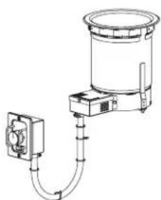
natural_image
Technical line drawing of a mechanical device with tubing and a cylindrical component (no text or symbols)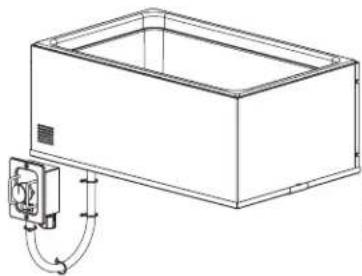
natural_image
Technical line drawing of a rectangular enclosure with a coiled cable and ventilation duct (no text or symbols)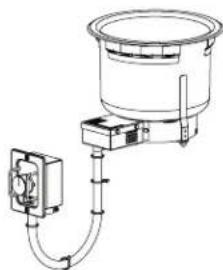
natural_image
Technical line drawing of a mechanical or electrical device with no visible text, numbers, or symbols.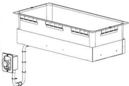
natural_image
Technical line drawing of a rectangular enclosure with internal partitions and an electrical outlet tube (no text or symbols)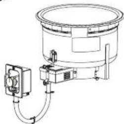
natural_image
Technical line drawing of a cylindrical industrial device with attached piping and control panel (no text or symbols)WARNING
Do not operate this equipment unless you have read and understood the contents of this manual! Failure to follow the instructions contained in this manual may result in serious injury or death. This manual contains important safety information concerning the maintenance, use, and operation of this product. If you're unable to understand the contents of this manual, please bring it to the attention of your supervisor. Keep this manual in a safe location for future reference.
English = p 2
ADVERTENCIA
Important Owner Information....2
Introduction....2
Important Safety Information....3
Model Designation 4
Model Description 5
Specifications 8
Plug Configurations 8
Electrical Rating Charts....9
Water Supply Specifications (Auto-Fill Units).... 11
Dimensions....11
Installation....14
General....14
Combustible Countertop Cutout Chart (for Unit/Mounting Kit)....16
Non-Combustible Countertop Cutout Chart ....18
Installing a Remote Control Enclosure....19
Control Enclosure Cutout Dimensions 19
Installing an Auto-Fill Unit....20
Installing a Drain Assembly 20
Installing a Bottom Mount Unit 20
Operation....21
General....21
Maintenance....22
General....22
Daily Cleaning 22
Removing Lime and Mineral Deposits ....22
Troubleshooting Guide....23
Options and Accessories 24
Limited Warranty 27
Authorized Parts Distributors......Back Cover
IMPORTANT OWNER INFORMATION
Record the model number, serial number, voltage, and purchase date of the unit in the spaces below (specification label located on the bottom of the unit or on the control enclosure). Please have this information available when calling Hatco ^® for service assistance.
Model No. ____
Serial No.
Voltage
Date of Purchase
Register your unit!
Completing online warranty registration will prevent delay in obtaining warranty coverage. Access the Hatco website at www.hatcocorp.com, select the Support pull-down menu, and click on "Warranty".
Business
Hours: 7:00 AM to 5:00 PM Monday–Friday, Central Time (CT)
(Summer Hours — June to September:
7:00 AM to 5:00 PM Monday–Thursday
7:00 AM to 4:00 PM Friday)
Telephone: 414-671-6350
E-mail: support@hatcocorp.com
24 Hour 7 Day Parts and Service Assistance available in the United States and Canada by calling 414-671-6350.
Additional information can be found by visiting our web site at www.hatcocorp.com.
INTRODUCTION
Hatco Built-In Heated Wells are specially designed to hold heated foods at safe serving temperatures. Designed for dry or wet applications, the wells are available in a variety of pan and pot combinations—all heated with a long-life metal sheath heating element design with a 2 year parts only warranty. Heat is evenly distributed throughout the heavy gauge stainless steel construction to assure hot food. The design allows for easy maintenance and durable performance. The standard unit is Underwriters Laboratory (UL) approved and equipped with a remote control enclosure. An optional UL recognized (UR) unit with remote switch is available also.
Units are equipped with EZ lock mounting hardware (except for the insulated bottom mount and round insulated models). One year parts and on-site labor warranty is standard.
Hatco Built-In Heated Wells are a product of extensive research and field testing. The materials used were selected for maximum durability, attractive appearance, and optimum performance. Every unit is inspected and tested thoroughly prior to shipment.
This manual provides the installation, safety, and operating instructions for the Built-In Heated Wells. Hatco recommends all installation, operating, and safety instructions appearing in this manual be read prior to installation or operation of the Built-In Heated Wells.

WARNING
WARNING indicates a hazardous situation which, if not avoided, could result in death or serious injury.

CAUTION
CAUTION indicates a hazardous situation which, if not avoided, could result in minor or moderate injury.
NOTICE
NOTICE is used to address practices not related to personal injury.

Read the following important safety information before using this equipment to avoid serious injury or death and to avoid damage to equipment or property.
WARNING
ELECTRIC SHOCK HAZARD:
- Unit must be installed by a qualified electrician. Installation must conform to all local electrical codes. Installation by unqualified personnel will void unit warranty and may lead to electric shock or burn, as well as damage to unit and/or its surroundings.
- Turn OFF power switch, unplug power cord/turn off power at circuit breaker, and allow unit to cool before performing any cleaning, adjustments, or maintenance.
- DO NOT submerge or saturate with water. Unit is not waterproof. Do not operate if unit has been submerged or saturated with water.
- Unit is not weatherproof. Locate the unit indoors where the ambient air temperature is a minimum of 70^ (21°C).
- Remote mounted control panel must be mounted on a vertical wall and installed in the vertical position. Mounting control panel in the horizontal position may result in collection of liquids and lead to electric shock.
- Operating voltage of remote control enclosure water valve exceeds 50 V (extra low voltage). Enclosure is marked with the following hazard identification symbol: 4
- Do not use unit to melt or hold ice. Doing so may cause condensation, creating an electrical hazard and causing personal injury and/or damage to unit. Damage caused by condensation is not covered by warranty.
- For non-Auto-Fill units, turn off unit when filling with water and avoid splashing.
- Do not clean the unit when it is energized or hot.
- This unit is not "jet-proof" construction. Do not use jet-clean spray to clean this unit.
- This unit must be serviced by qualified personnel only. Service by unqualified personnel may lead to electric shock or burn.
- Use only Genuine Hatco Replacement Parts when service is required. Failure to use Genuine Hatco Replacement Parts will void all warranties and may subject operators of the equipment to hazardous electrical voltage, resulting in electrical shock or burn. Genuine Hatco Replacement Parts are specified to operate safely in the environments in which they are used. Some aftermarket or generic replacement parts do not have the characteristics that will allow them to operate safely in Hatco equipment.
FIRE HAZARD:
- Install unit with a minimum of 3-1/2" (89 mm) of space from bottom of unit to all combustible surfaces to prevent combustion.
- Unit must be installed using ribbon putty gasket between unit and installation surface per installation instructions (refer to Installation section of this manual).
- Do not use flammable cleaning solutions to clean this unit.
WARNING
This unit must be installed by qualified, trained installers. Installation must conform to all local electrical and plumbing codes. Check with local plumbing and electrical inspectors for proper procedures and codes.
This unit is not intended for use by children or persons with reduced physical, sensory, or mental capabilities. Ensure proper supervision of children and keep them away from unit.
Make sure all operators have been instructed on the safe and proper use of unit.
Make sure food product has been heated to the proper food-safe temperature before placing in unit. Failure to heat food product properly may result in serious health risks. This unit is for holding pre-heated food product only.
Hatco Corporation is not responsible for actual food product serving temperature. It is the responsibility of the user to ensure that food product is held and served at a safe temperature.
This unit has no "user-serviceable" parts. If service is required on this unit, contact an Authorized Hatco Service Agent or contact the Hatco Service Department at 414-671-6350.
CAUTION
BURN HAZARD:
- Some exterior surfaces on the unit will get hot. Use caution when touching these areas.
- Drain water may reach temperatures in excess of 200°F (93°C). Use appropriate plumbing materials installing drain.
Locate unit at proper counter height in an area that is convenient for use. The location should be level to prevent the unit or its contents from falling accidentally and strong enough to support the weight of the unit and contents.
Auto-Fill units must be installed with adequate backflow protection and must conform with all federal, state, and local codes.
NOTICE
Auto-fill units supplied with water from a reverse osmosis (RO) system (or similar water filtration system) must be installed with an operating remineralization sytem to ensure proper operation. Failure to do so may cause unit to overfill. Damage caused by overfilling is not covered under warranty.
Units are voltage-specific. Refer to specification label for electrical requirements before beginning installation.
Standard and approved manufacturing oils may smoke up to 30 minutes during initial startup. This is a temporary condition. Operate unit without food product until smoke dissipates.
NOTICE
Unit must be allowed to cool down to room temperature before changing from wet-to-dry or dry-to-wet operation. Allowing unit to run dry during wet operation or adding water during dry operation will damage unit.
Do not locate unit in an area subject to excessive temperatures or grease from grills, fryers, etc. Excessive temperatures could cause damage to the unit.
Remote mounted control panels must have a minimum 6" (152 mm) clearance from unit (not to exceed 72" [1829 mm]). Mounting control panel closer may cause heat damage to electrical system in control panel.
Damage to any countertop material caused by heat generated from Hatco equipment is not covered under the Hatco warranty. Contact the manufacturer of the countertop material for application information.
NOTICE
Use non-abrasive cleaners and cloths only. Abrasive cleaners and cloths could scratch finish of unit, marring its appearance and making it susceptible to soil accumulation.
Do not use steel wool for cleaning. Steel wool will scratch the finish.
Do not use harsh chemicals such as bleach, cleaners containing bleach, or oven cleaners to clean this unit.
Drain sealants must have temperature rating of 500^ F or higher. Incoming water pipes must be FDA compliant for potable water.
MODEL DESIGNATION
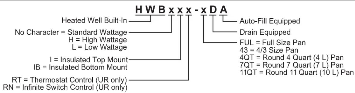
flowchart
graph TD
    A["Heated Well Built-In"] --> B["No Character = Standard Wattage"]
    A --> C["H = High Wattage"]
    A --> D["L = Low Wattage"]
    A --> E["I = Insulated Top Mount"]
    A --> F["IB = Insulated Bottom Mount"]
    A --> G["RT = Thermostat Control (UR only)"]
    A --> H["RN = Infinite Switch Control (UR only)"]
    I["Auto-Fill Equipped"] --> J["Drain Equipped"]
    K["FUL = Full Size Pan"] --> L["43 = 4/3 Size Pan"]
    M["4QT = Round 4 Quart (4 L) Pan"] --> N["7QT = Round 7 Quart (7 L) Pan"]
    O["11QT = Round 11 Quart (10 L) Pan"] --> P["End"]
All Models
All Built-In Heated Well units are reliable and versatile. Units have a stainless steel and aluminized steel housing with a metal sheathed heating element that is available in low, standard, and high wattage.
Heated Wells can be supplied with the heating element controlled in one of two ways. The first is UL listed with a thermostatic control and an ON/OFF switch housed in a remote control enclosure. The control enclosure is connected to the unit with a 36" (914 mm) flexible conduit assembly (72" [1829 mm] flexible conduit connection is optional, not available for retrofit). The second is a remote switch option that is UL recognized (UR) with either a thermostatic control and an ON/OFF switch or an infinite switch control with indicator light. The thermostatic control and ON/OFF switch is connected to the unit with a 36" (914 mm) flexible conduit assembly (72" [1829 mm] flexible conduit connection is optional, not available for retrofit).
Built-In Heated Wells can be hardwired directly to a power source for a secure and cord free serving area. Corded units also are available. EZ locking hardware allows for Heated Wells to be mounted into non-combustible countertops and combustible countertops using a Hatco® mounting kit accessory. Built-In Heated Wells are designed, manufactured, and tested to maintain safe food holding temperatures.
HWB-FUL Models
HWB-FUL models are capable of holding a variety of pan combinations listed below. These models are designed to be mounted to the topside of a non-combustible countertop or topside of a combustible countertop using the appropriate countertop mounting kit.
- One full size pan.
- Three 1/3 size pans with adapter bars.
- Two 1/2 sized pans with adapter bars.
- Two 7 quart (7 L) round pans with adapter top.
- Three 4 quart (4 L) round pans with adapter top.
An optional remote control enclosure with a digital temperature controller and an ON/OFF switch is available.
Pans, Covers, Adapter Bars, and Adapter Tops sold separately (see the OPTIONS AND ACCESSORIES section for details).
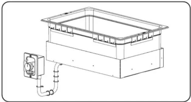
natural_image
Technical line drawing of a rectangular enclosure with a wall-mounted electrical outlet connected to a pipe (no text or symbols)HWB-FUL and HWB-FULD Models
HWB-FULD Models
HWB-FULD models have the same capabilities as the HWB-FUL but are equipped with a drain. The drain includes a 3/4" NPT drain fitting and flat drain screen that allows for pans to stay level for consistent temperatures. These models are designed to be mounted to the topside of a non-combustible countertop or topside of a combustible countertop using the appropriate countertop mounting kit.
HWB-FULDA Models
HWB-FULDA models have the same capabilities as the HWB-FULD but are equipped the optional Auto-Fill feature. The Auto-Fill feature fills and maintains the proper level of water in the well automatically. These models are designed to be mounted to the topside of a non-combustible countertop or topside of a combustible countertop using the appropriate countertop mounting kit.
HWBI-FUL Models
HWBI-FUL models are the same as the HWB-FUL models except the units are fully insulated. The insulated unit conserves energy and preserves more consistent heating temperatures. These models are designed to be mounted to the topside of a non-combustible countertop or topside of a combustible countertop using the appropriate countertop mounting kit.
HWBI-FULD Models
HWBI-FULD models are top mount insulated versions that have the same capabilities as the HWBI-FUL but with a drain. The drain includes a 3/4" NPT drain fitting and flat drain screen that allows for pans to stay level for consistent temperatures. These models are designed to be mounted to the topside of a non-combustible countertop or topside of a combustible countertop using the appropriate countertop mounting kit.
HWBI-FULDA Models
HWBI-FULDA models are top mount insulated versions that have the same capabilities as the HWBI-FULD but with the optional Auto-Fill feature. The Auto-Fill feature fills and maintains the proper level of water in the well automatically. These models are designed to be mounted to the topside of a non-combustible countertop or topside of a combustible countertop using the appropriate countertop mounting kit.
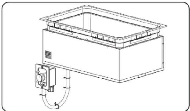
natural_image
Technical line drawing of a rectangular industrial device with internal components and piping (no text or symbols)HWBI-FUL and HWBI-FULD Models
HWBIB-FUL Models
HWBIB-FUL models are a fully insulated version of the HWB-FUL models. These models are designed to be mounted to the underside of a non-combustible countertop.
HWBIB-FULD Models
HWBIB-FULD models are bottom mount insulated versions that have the same capabilities as the HWBIB-FUL but with a drain. The drain includes a 3/4" NPT drain fitting and flat drain screen that allows for pans to stay level for consistent temperatures. These models are designed to be mounted to the underside of a non-combustible countertop.
HWBIB-FULDA Models
HWBIB-FULDA models are bottom mount insulated versions that have the same capabilities as the HWBIB-FULD but with the optional Auto-Fill feature. The Auto-Fill feature fills and maintains the proper level of water in the well automatically. These models are designed to be mounted to the underside of a non-combustible countertop.
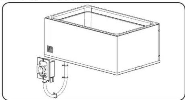
natural_image
Line drawing of a rectangular enclosure with a coiled piping system attached to its side (no text or symbols)HWBIB-FUL and HWBIB-FULD Models
HWB-43 Models
HWB-43 models are capable of holding a variety of pan combinations listed below. These models are designed to be mounted to the topside of a non-combustible countertop or topside of a combustible countertop using the appropriate countertop mounting kit.
• One full size pan and one 1/3 size pan with adapter bars.
- Four 1/3 size pans with adapter bars.
- Two 1/2 size pans and one 1/3 size pan with adapter bars.
- Two 11 quart (10 L) round pans with adapter top.
An optional remote control enclosure with a digital temperature controller and an ON/OFF switch is available.
Pans, Covers, Adapter Bars, and Adapter Tops sold separately (see the OPTIONS AND ACCESSORIES section for details).
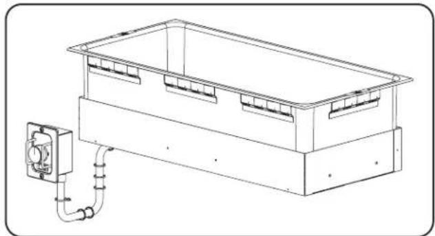
natural_image
Technical line drawing of a rectangular enclosure with internal partitions and a connected electrical outlet (no text or symbols)HWB-43 and HWB-43D Model
HWB-43D Models
HWB-43D models have the same capabilities as the HWB-43 but with a drain. The drain includes a 3/4" NPT drain fitting and flat drain screen that allows for pans to stay level for consistent temperatures. These models are designed to be mounted to the topside of a non-combustible countertop or topside of a combustible countertop using the appropriate countertop mounting kit.
HWB-43DA Models
HWB-43DA models have the same capabilities as the HWB-43D but with the optional Auto-Fill feature. The Auto-Fill feature fills and maintains the proper level of water in the well automatically. These models are designed to be mounted to the topside of a non-combustible countertop or topside of a combustible countertop using the appropriate countertop mounting kit.
HWBI-43 Models
HWBI-43 models are the same as the HWB-43 models except the units are fully insulated. The insulated unit conserves energy and preserves more consistent heating temperatures. These models are designed to be mounted to the topside of a non-combustible countertop or topside of a combustible countertop using the appropriate countertop mounting kit.
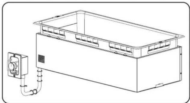
natural_image
Technical line drawing of an electrical enclosure with a wall-mounted power outlet and piping (no text or symbols)HWBI-43 and HWBI-43D Models
HWBI-43D Models
HWBI-43D models are top mount insulated versions that have the same capabilities as the HWBI-43 but with a drain. The drain includes a 3/4" NPT drain fitting and flat drain screen that allows for pans to stay level for consistent temperatures. These models are designed to be mounted to the topside of a non-combustible countertop or topside of a combustible countertop using the appropriate countertop mounting kit.
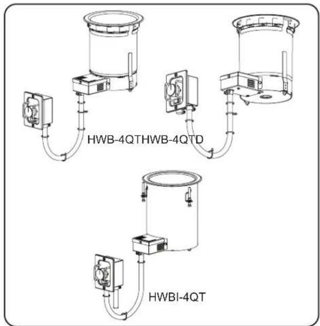
HWB-4QT Models
HWB-4QT models are round Built-In Heated Wells that hold a 4 quart (4 l) pan. These models are designed to be mounted to the topside of a non-combustible countertop or topside of a combustible countertop using the appropriate countertop mounting kit.
HWB-4QTD Models
HWB-4QTD models are the same as the HWB-4QT but are equipped with a drain. The drain includes a 3/4" NPT drain fitting and flat drain screen that allows for pans to stay level for consistent temperatures.
HWBI-4QT Models
HWBI-4QT models are the same as the HWB-4QT models except the units are fully insulated. The insulated unit conserves energy and preserves more consistent heating temperatures. These models are designed to be mounted to the topside of a non-combustible countertop using the appropriate countertop mounting kit.
HWBI-4QTD Models
HWBI-4QTD models are the same as the HWB-4QTD models except the units are fully insulated. The insulated unit conserves energy and preserves more consistent heating temperatures. These models are designed to be mounted to the topside of a non-combustible countertop using the appropriate countertop mounting kit.
text_image
HWB-4QTHWB-4QTD HWBI-4QTHWB-4QT, HWB-4QTD, and HWBI-4QT Model
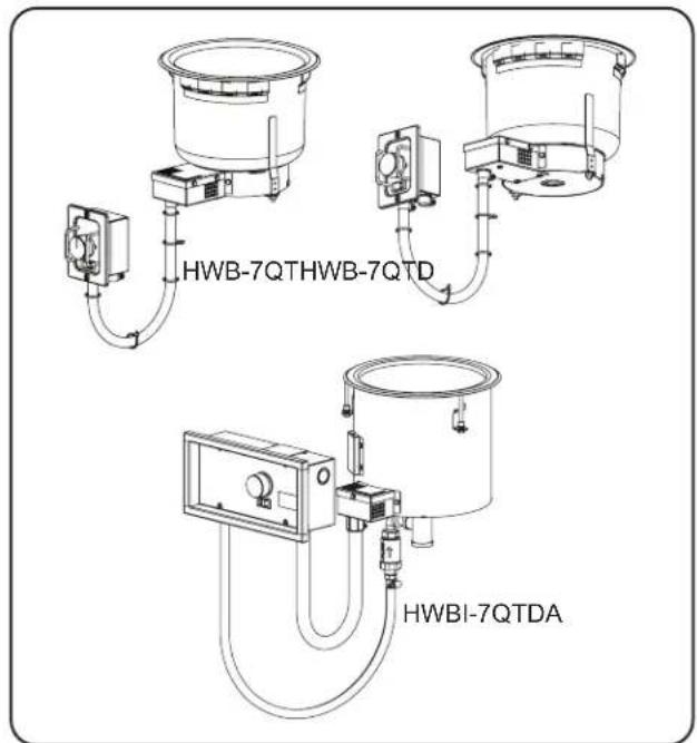
HWB-7QT Models
HWB-7QT models are round Built-In Heated Wells that hold a 7 quart (7 l) pan. These models are designed to be mounted to the topside of a non-combustible countertop or topside of a combustible countertop using the appropriate countertop mounting kit.
HWB-7QTD Models
HWB-7QTD models are the same as the HWB-7QT but is equipped with a drain. The drain includes a 3/4" NPT drain fitting and flat drain screen that allows for pans to stay level for consistent temperatures.
HWBI-7QT Models
HWBI-7QT models are the same as the HWB-7QT models except the units are fully insulated. The insulated unit conserves energy and preserves more consistent heating temperatures. These models are designed to be mounted to the topside of a non-combustible countertop using the appropriate countertop mounting kit.
HWBI-7QTD Models
HWBI-7QTD models are the same as the HWB-7QTD models except the units are fully insulated. The insulated unit conserves energy and preserves more consistent heating temperatures. These models are designed to be mounted to the topside of a non-combustible countertop using the appropriate countertop mounting kit.
HWBI-7QTDA Models
HWBI-7QTDA models have the same capabilities as the HWBI-7QTD models but are equipped the optional Auto-Fill feature. The Auto-Fill feature fills and maintains the proper level of water in the well automatically. These models are designed to be mounted to the topside of a non-combustible countertop using the appropriate countertop mounting kit.
text_image
HWB-7QTHWB-7QTD HWBI-7QTDAHWB-7QT, HWB-7QTD, and HWBI-7QT Models
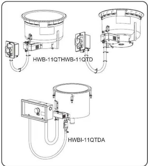
HWB-11QT Models
HWB-11QT models are round Built-In Heated Wells that hold a 11 quart (10 l) pan. These models are designed to be mounted to the topside of a non-combustible countertop or topside of a combustible countertop using the appropriate countertop mounting kit.
HWB-11QTD Models
HWB-11QTD models are the same as the HWB-11QT models but is equipped with a drain. The drain includes a 3/4" NPT drain fitting and flat drain screen that allows for pans to stay level for consistent temperatures.
HWBI-11QT Models
HWBI-11QT models are the same as the HWB-11QT models except the units are fully insulated. The insulated unit conserves energy and preserves more consistent heating temperatures. These models are designed to be mounted to the topside of a non-combustible countertop using the appropriate countertop mounting kit.
HWBI-11QTD Models
HWBI-11QTD models are the same as the HWB-11QTD models except the units are fully insulated. The insulated unit conserves energy and preserves more consistent heating temperatures. These models are designed to be mounted to the topside of a non-combustible countertop using the appropriate countertop mounting kit.
HWBI-11QTDA Models
HWBI-11QTDA models have the same capabilities as the HWBI-11QTD but are equipped the optional Auto-Fill feature. The Auto-Fill feature fills and maintains the proper level of water in the well automatically. These models are designed to be mounted to the topside of a non-combustible countertop using the appropriate countertop mounting kit.
text_image
HWB-11QTHWB-11QTD HWBI-11QTDAHWB-11QT, HWB-11QTD, and HWBI-11QT Models
SPECIFICATIONS
Plug Configurations
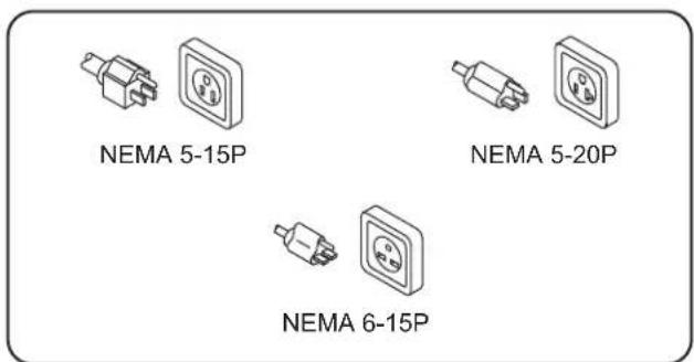
Some units are supplied from the factory with an electrical cord and plug installed. Plugs are supplied according to the application.
WARNING
ELECTRIC SHOCK HAZARD: Plug unit into a properly grounded electrical receptacle of the correct voltage, size, and plug configuration. If plug and receptacle do not match, contact a qualified electrician to determine and install the proper voltage and size electrical receptacle.
NOTE: The specification label is located on the bottom of the unit or on the control enclosure. See label for serial number and verification of unit electrical information.
text_image
NEMA 5-15P NEMA 5-20P NEMA 6-15PPlug Configurations
NOTE: Receptacle not supplied by Hatco ^® .
Electrical Rating Chart — All HWB-FUL Models
| Model | Voltage | Watts | Amps | Phase | Plug Configuration | Shipping Weight* |
| HWBLxx-FUL HWBLxx-FULD | 120 V | 750 W | 6.3 A | 1 | NEMA 5-15P or Hardwired | 21 lbs. (10 kg) |
| HWBLxx-FULDA | 120 V | 765 W | 6.4 A | 1 | NEMA 5-15P or Hardwired | 21 lbs. (10 kg) |
| HWBxx-FUL HWBxx-FULD | 120 V | 1200 W | 10.0 A | 1 | NEMA 5-15P or Hardwired | 21 lbs. (10 kg) |
| 208 V | 5.8 A | NEMA 6-15P or Hardwired | ||||
| 240 V | 5.0 A | |||||
| HWBxx-FULDA | 120 V | 1215 W | 10.1 A | 1 | NEMA 5-15P or Hardwired | 21 lbs. (10 kg) |
| 208 V | 5.9 A | NEMA 6-15P or Hardwired | ||||
| 240 V | 5.1 A | |||||
| HWBHxx-FUL HWBHxx-FULD | 120 V | 1650 W | 13.8 A | 1 | NEMA 5-20P or Hardwired | 21 lbs. (10 kg) |
| 208 V | 7.9 A | NEMA 6-15P or Hardwired | ||||
| 240 V | 6.9 A | |||||
| HWBHxx-FULDA | 120 V | 1665 W | 13.9 A | 1 | NEMA 5-20P or Hardwired | 21 lbs. (10 kg) |
| 208 V | 8.0 A | NEMA 6-15P or Hardwired | ||||
| 240 V | 7.0 A |
Electrical Rating Chart — All HWB-43 Models
| Model Voltage | Watts Amps Phase Shipping Weight* | ||||
| HWBLxx-43 120 | V 750 W 6.3 A 1 30 lbs. (14 kg) | ||||
| HWBLxx-43DA 120 | V 750 W 6.3 A 1 30 | bs. (14 kg) | |||
| HWBxx-43 120 V | 1200 W | 10.0 A | 1 30 lbs. | (14 kg)208 V 5.8 A | |
| 240 V 5.0 A | |||||
| HWBxx-43DA 120 | V | 1215 W | 10.1 A | 1 30 lbs. | (14 kg)208 V 5.8 A |
| 240 V 5.1 A | |||||
| HWBHxx-43 120 | V | 1650 W | 13.8 A | 1 30 lbs. | (14 kg)208 V 7.9 A |
| 240 V 6.9 A | |||||
| HWBHxx-43DA 120 | V | 1655 W | 13.9 A | 1 30 lbs. | (14 kg)208 V 8.0 A |
| 240 V 6.9 A | |||||
* Add 6 lbs. (3 kg) to shipping weight for insulated units. Add 3 lbs. (1 kg) to shipping weight for units with a drain. Add 3 lbs. (1 kg) to shipping weight for units with Auto-Fill.
NOTE: Shipping weight includes packaging and is estimated.
Electrical Rating Chart — All HWB-4QT Models
| Model Voltage | Watts Amps | Phase Plug | Configuration | Shipping Weight | ‡ |
| HWBxx-4QTHWBxx-4QTD | 120 V 500 | W 4.2 A | NEMA 5-15P or Hardwired | 9 lbs. (4 kg)208 V | |
| Hardwired | |||||
| 240 V 600 | W 2.5 A | ||||
| HWBHxx-4QTHWBHxx-4QTD | 120 V 800 | W 6.7 A | NEMA 5-15P or Hardwired | 9 lbs. (4 kg) | |
| 208 V 715 | W 3.4 A | Hardwired | |||
| 240 V 800 | W 3.3 A |
536 W 2.6 A
Electrical Rating Chart — All HWB-7QT Models
| Model Voltage Watts Amps Phase Plug Configuration Shipping Weight | ‡ | |||||
| HWBxx-7QTHWBxx-7QTD | 120 V 500 | W 4.2 A | 1 | NEMA 5-15P or Hardwired | 10 lbs. (5 kg)208 V | |
| Hardwired | ||||||
| 240 V 600 | W 2.5 A | |||||
| HWBxx-7QTDA | 120 V 515 | W 4.3 A | 1 | NEMA 5-15P or Hardwired | 10 lbs. (5 kg)208 V | |
| Hardwired | ||||||
| 240 V 615 | W 2.6 A | |||||
| HWBHxx-7QTHWBHxx-7QTD | 120 V 800 | W 6.7 A | 1 | NEMA 5-15P or Hardwired | 10 lbs. (5 kg) | |
| 208 V 715 | W 3.4 A | Hardwired | ||||
| 240 V 800 | W 3.3 A | |||||
| HWBHxx-7QTDA | 120 V 815 | W 6.8 A | 1 | NEMA 5-15P or Hardwired | 10 lbs. (5 kg) | |
| 208 V 730 | W 3.5 A | Hardwired | ||||
| 240 V 815 | W 3.4 A | |||||
536 W 2.6 A
551 W 2.6 A
Electrical Rating Chart — All HWB-11QT Models
| Model Voltage Watts Amps Phase Plug Configuration Shipping Weight | ‡ | |||||
| HWBxx-11QTHWBxx-11QTD | 120 V 500 | W 4.2 A | 1 | NEMA 5-15P or Hardwired | 11 lbs. (5 kg)208 V | |
| Hardwired | ||||||
| 240 V 600 | W 2.5 A | |||||
| HWBXX-11QTDA | 120 V 515 | W 4.3 A | 1 | NEMA 5-15P or Hardwired | 11 lbs. (5 kg) | |
| 208 V 551 | W 2.6 A | Hardwired | ||||
| 240 V 615 | W 2.6 A | |||||
| HWBHxx-11QTHWBHxx-11QTD | 120 V 800 | W 6.7 A | 1 | NEMA 5-15P or Hardwired | 11 lbs. (5 kg) | |
| 208 V 715 | W 3.4 A | Hardwired | ||||
| 240 V 800 | W 3.3 A | |||||
| HWBHXX-11QTDA | 120 V 815 | W 6.8 A | 1 | NEMA 5-15P or Hardwired | 11 lbs. (5 kg)208 V | |
| Hardwired | ||||||
| 240 V 815 | W 3.4 A | |||||
536 W 2.6 A
730 W 3.5 A
‡ Add 3 lbs. (1 kg) to shipping weight for units with a drain.
NOTE: Shipping weight includes packaging and is estimated.
Water Supply Specifications (Auto-Fill Units)
| Minimum Maximum | ||
| Water Pressure 25 | psi (172 kPa) | 100 psi (689 kPa) |
| Water Temperature | 60°F (15°C) | 110°F (43°C) |
NOTICE
Auto-fill units supplied with water from a reverse osmosis (RO) system (or similar water filtration system) must be installed with an operating remineralization sytem to ensure proper operation. Failure to do so may cause unit to overfill. Damage caused by overfilling is not covered under warranty.
Dimensions — HWB-FUL Models (Non-Insulated, Top Mount)
| Models: HWB-FUL HWBRN-FUL HWBRT-FUL HWB-FULD HWBRN-FULD HWBRT-FULD HWBL-FUL HWBLRN-FUL HWBLRT-FUL HWBL-FULD HWBLRN-FULD HWBLRT-FULD HWBH-FUL HWBHRN-FUL HWBHRT-FUL HWBH-FULD HWBHRN-FULD HWBHRT-FULD | ||
| Width (A) | Depth (B) | Height (C)† |
| 13-3/4" (347 mm) | 21-3/4" (553 mm) | 9-3/8" (237 mm) |
† For HWB-FUL units equipped with a cord and plug, Height dimension "C" is 15-1/8" (385 mm). The added height is for the control bracket mounted on the bottom of the unit.
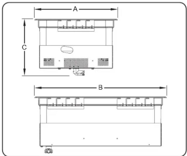
text_image
A C BDimensions — HWB-FUL Models
(Non-Insulated, Top Mount)
Dimensions — HWBI-FUL Models (Insulated, Top Mount)
| Models: | ||
| HWBI-FUL | HWBIRT-FUL | |
| HWBI-FULD | HWBIRT-FULD | |
| HWBLI-FUL | HWBLIRT-FUL | |
| HWBIL-FULD | HWBLIRT-FULD | |
| HWBHI-FUL | HWBHIRT-FUL | |
| HWBHI-FULD | HWBHIRT-FULD | |
| Width(A) | Depth(B) | Height(C) |
| 13-3/4"(347 mm) | 21-3/4"(553 mm) | 10-3/8"(263 mm) |
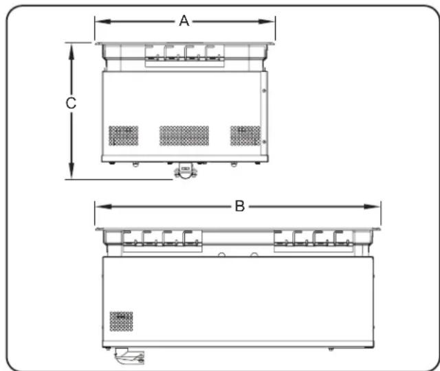
text_image
A C BDimensions — HWBI-FUL Models
(Insulated, Top Mount)
Dimensions — HWBIB-FUL Models (Insulated, Bottom Mount)
Models:
HWBIB-FUL HWBHIB-FUL
HWBIB-FULD HWBHIB-FULD
HWBIB-FULDA HWBHIB-FULDA
HWBLIB-FUL HWBLIBRT-FUL
HWBLIB-FULD HWBLIBRT-FULD
HWBLIB-FULDA HWBHIBRT-FUL
HWBIBRT-FUL HWBHIBRT-FULD
HWBIBRT-FULD
| Width (A) | Depth (B) | Height (C) |
| 13-7/8" (352 mm) | 22-1/8" (561 mm) | 10-3/8" (261 mm) |
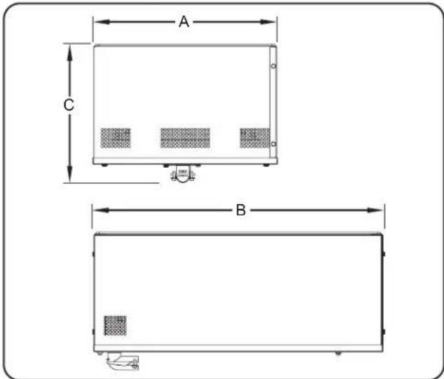
text_image
A C BDimensions — HWBIB-FUL Models (Insulated, Bottom Mount)
Dimensions — HWB-43 Models
Models:
HWB-43 HWB-43D HWB-43DA
HWBL-43 HWBL-43D HWBL-43DA
HWBH-43 HWBH-43D HWBH-43DA
HWBRT-43 HWBRT-43D HWBLRT-43
HWBLRT-43D HWBHRT-43 HWBHRT-43D
HWBRN-43 HWBRN-43D HWBLRN-43
HWBLRN-43D HWBHRN-43 HWBHRN-43D
| Width (A) | Depth (B) | Height (C) |
| 13-5/8" (345 mm) | 28-5/8" (726 mm) | 9-7/16" (239 mm) |
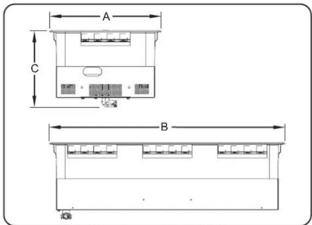
text_image
A C BDimensions — HWB-43 Models
Dimensions — HWBI-43 Models
Models:
HWBI-43 HWBI-43D HWBLI-43
HWBLI-43D HWBHI-43 HWBHI-43D
| Width (A) | Depth (B) | Height (C) |
| 13-5/8" (345 mm) | 28-5/8" (726 mm) | 10-5/16" (262 mm) |
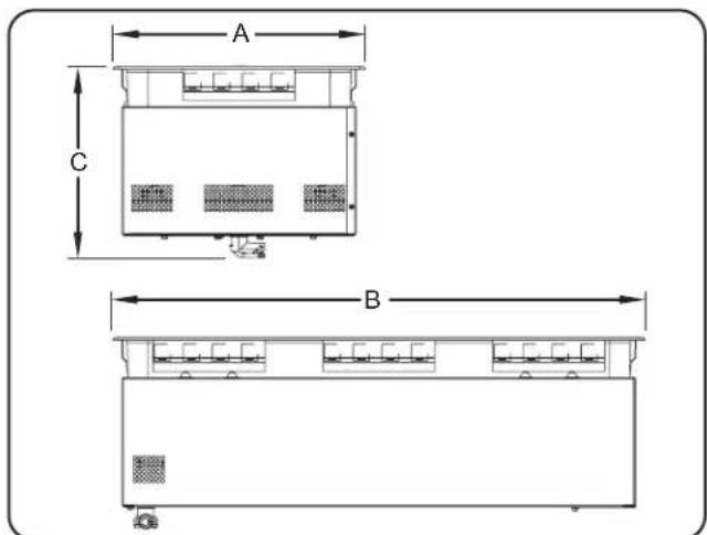
text_image
A C BDimensions — HWBI-43 Models
Dimensions — HWB-4QT Models
| Models: HWB-4QT HWBRN-4QT HWBRT-4QT HWB-4QTD HWBRN-4QTD HWBRT-4QTD HWBI-4QT HWBI-4QTD | |
| Diameter (A) | Height (B) |
| 8-3/8" (212 mm) | 10-5/8" (270 mm) |

text_image
A BDimensions — HWB-4QT Models
Dimensions — HWB-7QT Models
| Models: HWB-7QT HWBRN-7QT HWBRT-7QT HWB-7QTD HWBRN-7QTD HWBRT-7QTD HWBH-7QT HWBHRN-7QT HWBHRT-7QT HWBH-7QTD HWBHRN-7QTD HWBHRT-7QTD HWBI-7QT HWBI-7QTD HWBI-7QTDA HWBIH-7QT HWBIH-7QTD HWBIH-7QTDA | |
| Diameter (A) | Height (B) |
| 10-5/16" (262 mm) | 9-5/8" (244 mm) |
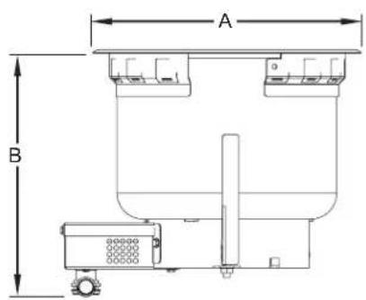
text_image
A BDimensions — HWB-7QT Models
Dimensions — HWB-11QT Models
| Models: HWB-11QT HWBRN-11QT HWBRT-11QT HWB-11QTD HWBRN-11QTD HWBRT-11QTD HWBH-11QT HWBHRN-11QT HWBHRT-11QT HWBH-11QTD HWBHRN-11QTD HWBHRT-11QTD HWBI-11QT HWBI-11QTD HWBI-11QTDA HWBIH-11QT HWBIH-11QTD HWBIH-11QTDA | |
| Diameter (A) | Height (B) |
| 12-5/16" (313 mm) | 9-5/8" (244 mm) |
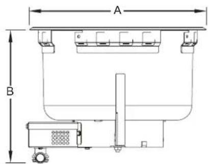
text_image
A BDimensions — HWB-11QT Models
General
Built-In Heated Well units are shipped from the factory with most components assembled and ready for use. Use the following procedures to install the unit.
WARNING
ELECTRIC SHOCK HAZARD: Unit is not weatherproof. Locate unit indoors where ambient air temperature is a minimum of 70^ F ( 21^ C).
FIRE HAZARD:
• Install unit with a minimum of 3-1/2" (89 mm) of space from bottom of unit to all combustible surfaces to prevent combustion.
- Unit must be installed using ribbon putty gasket between the unit and the installation surface per installation instructions.
This unit must be installed by qualified, trained installers. Installation must conform to all local electrical and plumbing codes. Check with local plumbing and electrical inspectors for proper procedures and codes.
CAUTION
Locate the unit at the proper counter height in an area that is convenient for use. The location should be strong enough to support the weight of the unit and contents.
NOTICE
Units are voltage-specific. Refer to specification label for electrical requirements before beginning installation.
Do not locate unit in an area subject to excessive temperatures or grease from grills, fryers, etc. Excessive temperatures could cause damage to the unit.
Unit is designed and recommended for use in or on metallic countertops. Damage to any countertop material is not covered under the Hatco® warranty. For other surfaces, verify with manufacturer that material is suitable for prolonged temperatures up to 200°F (93°C).
NOTICE
Remote mounted control panels must have a minimum 6" (152 mm) clearance from unit (not to exceed [1829 mm]). Mounting control panel closer may cause heat damage to electrical system in control panel.
72"
Damage to any countertop material caused by heat generated from Hatco equipment is not covered under the Hatco warranty. Contact the manufacturer of the countertop material for application information.
NOTE: All Built-In Heated Wells require the control enclosure be remote mounted in the vertical position.
- Remove the unit from the box.
NOTE: To prevent delay in obtaining warranty coverage, complete online warranty registration. See the IMPORTANT OWNER INFORMATION section for details.
- Remove tape and protective packaging from all surfaces of unit.
NOTE: A qualified electrician is recommended for connecting the Built-In Heated Well units to a power source. A qualified plumber is recommended for connecting drain.
- Install the unit in the desired location. Use the appropriate procedure in this section for combustible or non-combustible countertops.
IMPORTANT NOTE:
For bottom mount units, see "Installing a Bottom Mount Unit" in this section or "Mounting Bracket for Bottom Mount Units" in the OPTIONS AND ACCESSORIES section before performing any countertop cutouts.
- Install the remote control enclosure (refer to the procedure in this section).
Installing Top Mount Unit into Combustible Countertop
WARNING
FIRE HAZARD:
- Hatco mounting flange kits must be used when mounting unit in a combustible countertop.
- Unit must be installed using ribbon putty gasket between the unit and the installation surface per installation instructions.
NOTE: Cut the opening for both the mounting flange/unit and the control enclosure before placing the assembly into the countertop opening.
NOTE: Make sure the installation location provides enough room for the remote control enclosure, electrical connections, and plumbing connections.
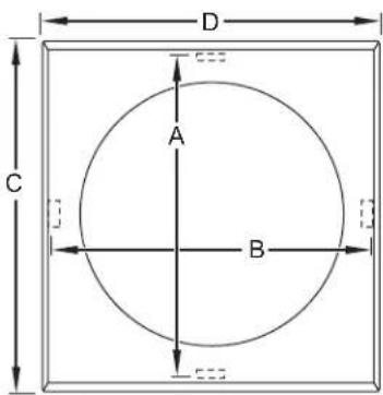
- Cut the appropriate opening for the mounting flange into the countertop. Refer to "Combustible Countertop Cutout Chart (for Unit/Mounting Kit)" in this section.
- Cut the appropriate opening for the control enclosure. Refer to "Control Enclosure Cutout Dimensions" in this section.
- Place ribbon putty gasket around the cutout edge of the countertop. Make sure the ribbon putty gasket overhangs the cutout edge or seal the unit with silicone adhesive.
NOTE: A roll of ribbon putty gasket material is supplied with the unit.
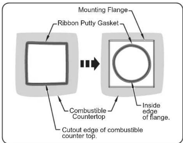
flowchart
graph TD
    A["Rectangle"] --> B["Mounting Flange"]
    B --> C["Ring Box"]
    C --> D["Combustible Countertop"]
    D --> E["Cutout Edge of Combustible Counter Top."]
    C --> F["Inside Edge of Flange."]
Installing Ribbon Putty Gasket
-
Place the mounting flange into the countertop opening.
-
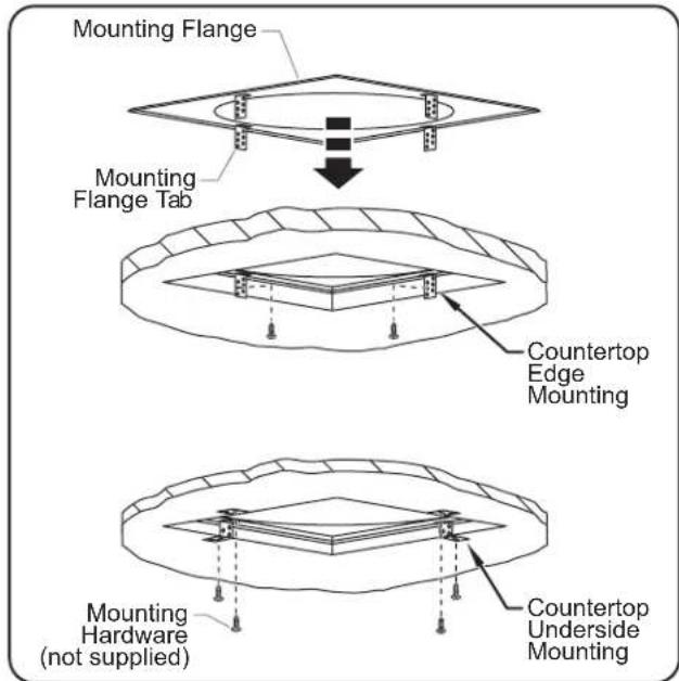
Secure the mounting flange tabs to the edge or the underside of the combustible countertop using the appropriate hardware (mounting hardware not supplied).
NOTE: For underside mounting, tabs on mounting flange must be bent to the underside of the countertop.
text_image
Mounting Flange Mounting Flange Tab Countertop Edge Mounting Mounting Hardware (not supplied) Countertop Underside MountingInstallation of Mounting Flange Kit
-
Place ribbon putty gasket around the inside edge of the mounting flange. Make sure the ribbon putty gasket overhangs the edge of the flange or seal the unit with silicone adhesive.
-
Place the unit into the mounting flange opening.
-
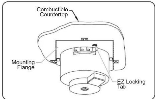
Using a screwdriver, rotate the unit's EZ locking tab outward to secure the unit to the underside of the mounting flange. Rotate as many tabs as needed to secure the unit to the mounting flange.
text_image
Combustible Countertop Mounting Flange EZ Locking TabEZ Locking Tabs
- Carefully trim and remove the excess ribbon putty gasket material from around the unit.
| Combustible Countertop Cutout Chart (for Unit/Mounting Kit) | |||||||
| Models | Minimum Width (A) | Maximum Width (A) | Minimum Depth (B) | Maximum Depth (B) | Overall Width (C) | Overall Depth (D) | Below Counter Clearance |
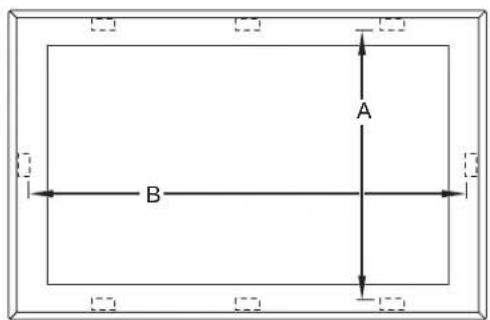
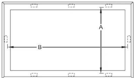
| HWB-FUL 14 | "(356 mm) | 14-1/4"(362 mm) | 22"(559 mm) | 22-1/4"(565 mm) | --- | --- | 10-1/2"(267 mm) |
| HWB-43 | 14"(356 mm) | 14-1/4"(362 mm) | 29"(737 mm) | 29-1/4"(743 mm) | --- | --- | 10"(254 mm) |
| HWBI-43 | --- | --- | |||||
| HWB-4QT♦ | 9"(229 mm) | 9-1/4"(235 mm) | 9"(229 mm) | 9-1/4"(235 mm) | 10"(254 mm) | 10"(254 mm) | 11"(279 mm) |
| HWB-7QT♦ | 11"(279 mm) | 11-1/4"(286 mm) | 11"(279 mm) | 11-1/4"(286 mm) | 12"(305 mm) | 12"(305 mm) | 10"(254 mm) |
| HWB-11QT♦ | 13"(330 mm) | 13-1/4"(337 mm) | 13"(330 mm) | 13-1/4"(337 mm) | 14"(356 mm) | 14"(356 mm) | 10"(254 mm) |
Combustible countertop opening is a "square" cut-out.
NOTE: Mounting kit required for combustible countertop installations.
NOTE: Allow additional clearance below the counter for units equipped with a drain.
text_image
A BHWB-FUL Models HWB-43 and HWBI-43 Models
text_image
A B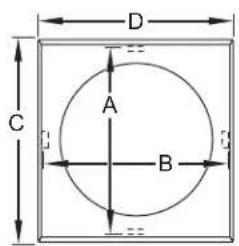
text_image
D A B C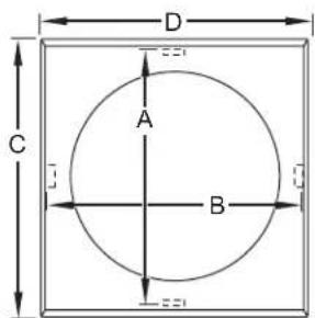
text_image
D A B CHWB-4QT Models HWB-7QT Models HWB-11QT Models
text_image
D A C BCombustible Countertop Mounting Flange Templates
Installing Top Mount Unit into Non-Combustible Countertop
WARNING
FIRE HAZARD: Unit must be installed using ribbon putty gasket between unit and installation surface per installation instructions (refer to Installation section of this manual).
NOTE: Mounting flange kit is not required for installation into non-combustible material.
NOTE: Cut the opening for both the unit and the control enclosure before placing unit into the countertop opening.
NOTE: Make sure the installation location provides enough room for the remote control enclosure, electrical connections, and plumbing connections.
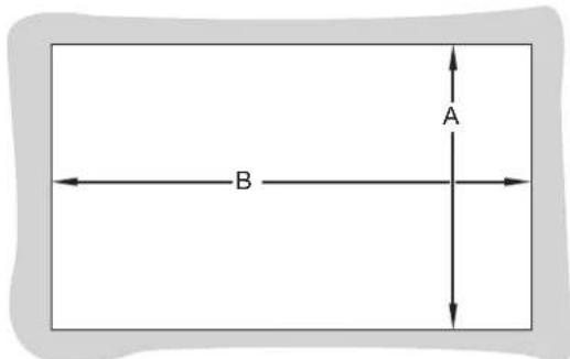
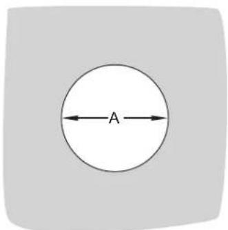
- Cut the appropriate opening in the countertop. Refer to "Non-Combustible Countertop Cutout Chart" in this section.
- Cut the appropriate opening for the control enclosure. Refer to "Control Enclosure Cutout Dimensions" in this section.
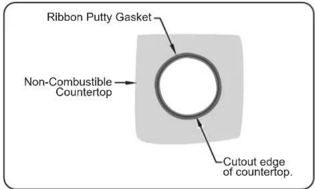
- Place ribbon putty gasket around the cutout edge of the countertop. Make sure the ribbon putty gasket overhangs the cutout edge or seal unit with silicone adhesive.
text_image
Ribbon Putty Gasket Non-Combustible Countertop Cutout edge of countertop.Installing Ribbon Putty Gasket
NOTE: A roll of ribbon putty gasket material is supplied with the unit.
-
Place the unit into the countertop opening.
-
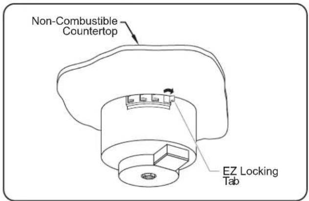
Using a screwdriver, rotate the unit's EZ locking tab outward to secure the unit to the underside of the countertop. Rotate as many tabs as needed to secure the unit to the countertop.
text_image
Non-Combustible Countertop EZ Locking TabEZ Locking Tabs
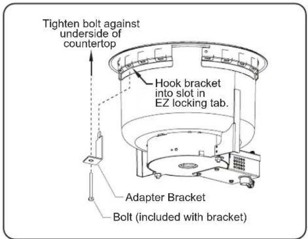
NOTE: The Hatco® EZ locking tabs work on countertops that have a maximum thickness of 3/16" (5 mm). For countertops 3/16"-2" thick, use optional adapter bracket P/N R04.42.194.00. Refer to the OPTIONS AND ACCESSORIES section for more information.
text_image
Tighten bolt against underside of countertop Hook bracket into slot in EZ locking tab. Adapter Bracket Bolt (included with bracket)Thick Countertop Adapter Bracket
- Carefully trim and remove the excess ribbon putty material from around the unit.
| Non-Combustible Countertop Cutout Chart | |||||
| Models | Minimum Width (A) | Maximum Width (A) | Minimum Depth (B) | Maximum Depth (B) | Below Counter Clearance |
| HWB-FUL 12-58 | "(321 mm) | 12-15/16"(328 mm) | 20-5/8"(524 mm) | 20-15/16"(531 mm) | 10-1/2"(267 mm) |
| HWBIB-FUL■ | 12-1/32"(306 mm) | 12-1/32"(306 mm) | 20-1/32"(509 mm) | 20-1/32"(509 mm) | 10-1/2"(267 mm) |
| HWB-43 HWBI-43 | 12-11/16"(323 mm) | 12-15/16"(328 mm) | 27-11/16"(704 mm) | 28"(711 mm) | 10"(254 mm) |
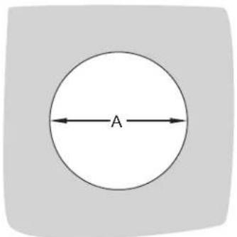
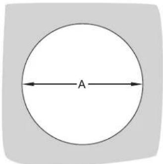
| HWB-4QT ∅ 7-1/8 | "(181 mm) | ∅ 7-9/16"(192 mm) | --- | --- | 11"(279 mm) |
| HWBI-4QT ∅ 7-3/8 | "(187 mm) | ∅ 7-9/16"(192 mm) | --- | --- | 11"(279 mm) |
| HWB-7QT ∅ 9-1/8 | "(232 mm) | ∅ 9-9/16"(243 mm) | --- | --- | 10"(254 mm) |
| HWBI-7QT ∅ 9-9/16 | "(243 mm) | ∅ 9-9/16"(243 mm) | --- | --- | 10"(254 mm) |
| HWB-11QT ∅ 11-1/8 | "(282 mm) | ∅ 11-9/16"(294 mm) | --- | --- | 10"(254 mm) |
| HWBI-11QT ∅ 11-3/8 | "(289 mm) | ∅ 11-9/16"(294 mm) | --- | --- | 10"(254 mm) |
■ Refer to "Installing A Bottom Mount Unit" in the INSTALLATION section for additional cutout dimensions using flange installation. If using optional Mounting Brackets, refer to "Mounting Brackets for Bottom Mount Units" in the OPTIONS AND ACCESSORIES section.
NOTE: Allow additional clearance below the counter for units equipped with a drain.
text_image
A BHWB-FUL, HWBI-FUL, HWBIB-FUL, HWB-43, and HWBI-43 Models
text_image
AHWB-4QT and HWBI-4QT Models
text_image
AHWB-7QT and HWBI-7QT Models
text_image
AHWB-11QT and HWBI-11QT Models
Non-Combustible Countertop Mounting Templates
Installing a Remote Control Enclosure
WARNING
ELECTRIC SHOCK HAZARD:
- The remote control enclosure must be mounted on a vertical wall and installed in the vertical position. Mounting the control enclosure in the horizontal position may result in the collection of liquids and lead to an electric shock.
- Operating voltage of remote control enclosure water valve exceeds 50 V (extra low voltage). Enclosure is marked with the following hazard identification symbol: 12
NOTE: A qualified electrician is recommended for connecting the unit to a power source. A qualified plumber is recommended for connecting drain(s) and Auto-Fill.
- Cut and drill the appropriate holes in the mounting surface. Refer to the "Control Enclosure Cutout Dimensions" below for the cutout dimensions for each control enclosure.
- Remove the trim cover from the control enclosure assembly.
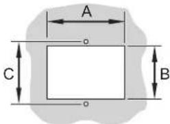
| Control Enclosure Cutout Dimensions | ||||
| Model | Opening Dimensions | Screw Hole Dimensions | ||
| (A) | (B) (C) | (D) | ||
| Control Box Assembly Without Bezel (standard) | 2-3/16" (55 mm) | 3-3/8" (86 mm) | 3-1/4" (83 mm) | 2-1/2" (64 mm) |
| Control Box Assembly With Bezel (standard) | 3-1/4" (83 mm) | 3-3/4" (95 mm) | 4-1/8" (105 mm) | --- |
| Recessed Control Box Assembly (optional) | 5-7/8" (149 mm) | 6-3/8" (162 mm) | 6-13/16" (173 mm) | 3-7/8" (98 mm) |
| Control Panel for UR Units | 2-1/8" (54 mm) | 3-3/8" (86 mm) | 3-1/2" (89 mm) | 2-1/4" (57 mm) |
| WM Control Assembly (optional) | 4-3/4" (121 mm) | 5" (127 mm) | 5-1/4" (133 mm) | 3" (76 mm) |
| Control Box Assembly with Auto-Fill (optional) | 10-1/8" (257 mm) | 4-3/4" (121 mm) | 2-1/2" (64 mm) | 10-7/16" (264 mm) |
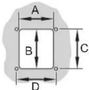
Control Box Without Bezel (standard)
text_image
A C BControl Box With Bezel (standard)
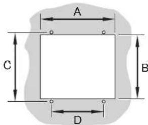
text_image
A C B DRecessed Control Box (optional)
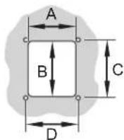
Control Panel For UR Units
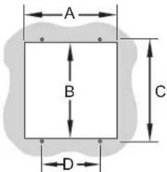
text_image
A B C DWM Control Box (optional)
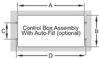
text_image
Control Box Assembly With Auto-Fill (optional)IMPORTANT NOTE:
Make sure the installation location provides enough room for electrical and plumbing connections to the control enclosure. Follow local and national plumbing and electrical codes.
Control Enclosure Assembly Cutout Dimensions
Installing an Auto-Fill Unit
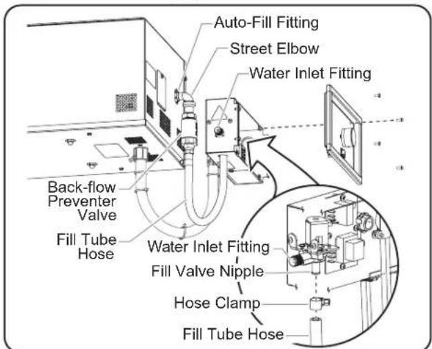
The side mounted Auto-Fill option connects the on-site water supply through the control panel to an Auto-Fill fitting on the side of the well enclosure. Use the following procedure to install a unit equipped with the side mounted Auto-Fill option.
NOTE: The Plumbing Kit that comes with this unit includes the following parts: street elbow, back-flow preventer valve, fill tube hose, and hose clamps.
CAUTION
Auto-Fill units must be installed with adequate backflow protection and must conform with federal, state, and local codes.
NOTICE
Auto-fill units supplied with water from a reverse osmosis (RO) system (or similar water filtration system) must be installed with an operating remineralization sytem to ensure proper operation. Failure to do so may cause unit to overfill. Damage caused by overfilling is not covered under warranty.
Drain sealants must have temperature rating of 500^ F or higher. Incoming water pipes must be FDA compliant for potable water.
- Connect the street elbow to the Auto-Fill fitting located on the outside of the well. Replace the fill tube hose on fitting.
NOTE: The fill tube hose may need to be removed from the Plumbing Kit for ease of installation. - Connect the fill tube hose to the fill valve nipple in the control enclosure and secure using the hose clamp. (Disassemble the control enclosure trim cover to access the nipple.)
- Connect the on-site water supply line to the 1/4" NPT water inlet fitting on the control enclosure.
- Turn on the water supply and check for leaks.
text_image
Auto-Fill Fitting Street Elbow Water Inlet Fitting Back-flow Preventer Valve Fill Tube Hose Water Inlet Fitting Fill Valve Nipple Hose Clamp Fill Tube HoseInstalling a Side Mounted Auto-Fill Unit (HWBIB-FULDA shown)
NOTE: Refer to "Water Supply Specifications" in the SPECIFICATIONS section of this manual for water supply requirements.
Installing A Drain Assembly
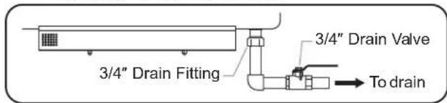
After installing a drain-equipped unit into the countertop, use the following procedure to connect the unit to the on-site drain line.
NOTE: Consult a licensed plumbing contractor for proper drain installation that conforms to local plumbing codes.
NOTE: Approved air gap or other back-flow prevention device must be installed by a licensed plumber, if required.
CAUTION
BURN HAZARD: Drain water may reach temperatures in excess of 200°F (93°C). Use appropriate plumbing materials when installing drain.
- Connect drain pipe (supplied by others) from the 3/4" NPT drain fitting on the bottom of the unit to a 3/4" drain valve (available as an accessory from Hatco®).
NOTE: The drain valve must be installed in an easily accessible location for the operator.
- Connect the drain valve to the on-site drain line (not supplied).
NOTE: Hatco recommends using a union fitting with the drain assembly for ease of servicing.
text_image
3/4" Drain Fitting 3/4" Drain Valve To drainDrain Connection
Installing a Bottom Mount Unit
Installation of a bottom mount unit requires custom fabrication of the countertop by a qualified and experienced installer. Use the following information as guidelines for one method of installing a bottom mount unit. Refer to the OPTIONS AND ACCESSORIES section for installation with an optional mounting bracket.
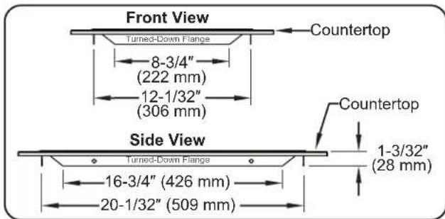
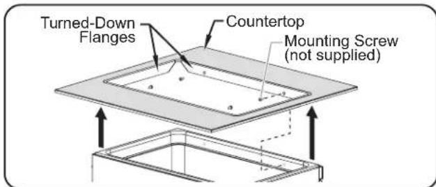
- Create the countertop cutout with turned-down flanges on all four sides. These flanges should be positioned on the inside of the well for installation.
text_image
Front View Turned-Down Flange 8-3/4" (222 mm) 12-1/32" (306 mm) Side View Turned-Down Flange 16-3/4" (426 mm) 20-1/32" (509 mm) Countertop Countertop 1-3/32" (28 mm)Suggested Turned-Down Flange Dimensions
- Apply silicone sealant to the top edge of the well before installation.
- Secure the unit to the countertop by installing mounting screws (not supplied) through the turned-down flanges and into the top rim of the well.
text_image
Turned-Down Flanges Countertop Mounting Screw (not supplied)Installing Bottom Mount Unit
General
Use the following procedures to operate a Built-In Heated Well.
WARNING
Read all safety messages in the IMPORTANT SAFETY INFORMATION section before operating this equipment.
ELECTRIC SHOCK HAZARD:
- Do not use unit to melt or hold ice. Doing so may cause condensation, creating an electrical hazard and causing personal injury and/or damage to unit. Damage caused by condensation is not covered by warranty.
- For units without Auto-Fill, turn off unit when filling with water and avoid splashing.
NOTICE
Auto-fill units supplied with water from a reverse osmosis (RO) system (or similar water filtration system) must be installed with an operating remineralization sytem to ensure proper operation. Failure to do so may cause unit to overfill. Damage caused by overfilling is not covered under warranty.
Standard and approved manufacturing oils may smoke up to 30 minutes during initial startup. This is a temporary condition. Operate unit without food product until smoke dissipates.
Unit must be allowed to cool down to room temperature before changing from wet-to-dry or dry-to-wet operation. Allowing unit to run dry during wet operation or adding water during dry operation will damage unit.
Hatco Built-In Heated Wells are designed for WET or DRY operation. Hatco recommends wet operation for consistent food heating. If the unit is operating wet and is allowed to run dry, turn it off and allow to cool before adding water.
Startup
- Prepare the heated well for operation.
- If using the well for wet operation without Auto-Fill, make sure the drain valve is closed (if equipped) and manually fill the well with hot tap water until the water is a maximum of 1-1/4" (32 mm) deep.
- If the unit is equipped with the Auto-Fill option, make sure the drain valve is closed.
- Place an empty pan in the well or cover the well with a lid. This step is recommended to speed up pre-heating and reach operating temperature.
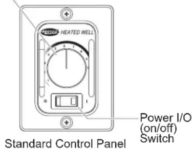
- Move the Power I/O (on/off) switch to the I (on) position. The indicator light on the switch glows when the unit is on.
- If the unit is equipped with the Auto-Fill option, the Power I/O switch will activate the Auto-Fill system when it is moved to the I (on) position. The well will fill with water until the water reaches the water level sensor in the well. During operation, the Auto-Fill system will maintain the water level automatically using the water level sensor.
- Turn the Temperature Control Knob to adjust the temperature of the unit to the desired safe food temperature.
- Allow heated well to preheat for approximately 30 minutes.
WARNING
Hatco Corporation is not responsible for actual food product serving temperature. It is the responsibility of the user to ensure that food product is held and served at a safe temperature.
Temperature Control Knob
text_image
HEATED WELL Standard Control Panel Power I/O (on/off) Switch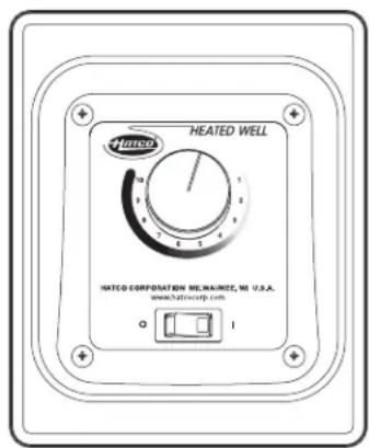
text_image
HEATED WELL HATCO CORPORATION ME,MAINEE, MI U.S.A. www.hatcoepf.comOptional Recessed Control Panel w/Mechanical Temperature Control
Control Panels
NOTE: Refer to the OPTIONS AND ACCESSORIES section for units equipped with the optional digital temperature controller.
Food Warming
Place the appropriate size food pan(s) into the unit opening.
- Always use a food pan. Do not place food directly into the warmer.
- Stir thick food items frequently to keep food heated uniformly.
- Keep pans covered to maintain food quality and temperature.
Shutdown
- Move the Power I/O (on/off) switch to the O (off) position. The indicator light on the switch will shut off and the Auto-Fill system will be deactivated (if equipped).
General
Hatco® Built-In Heated Wells are designed for maximum durability and performance, with minimum maintenance.
WARNING
ELECTRIC SHOCK HAZARD:
- Turn OFF power switch, unplug power cord/turn off power at circuit breaker, and allow unit to cool before performing any cleaning, adjustments, or maintenance.
- DO NOT submerge or saturate with water. Unit is not waterproof. Do not operate if unit has been submerged or saturated with water.
- Do not clean unit when it is energized or hot.
- This unit is not "jet-proof" construction. Do not use jet-clean spray to clean this unit.
FIRE HAZARD: Do not use flammable cleaning solutions to clean this unit.
This unit has no "user-serviceable" parts. If service is required on this unit, contact an Authorized Hatco Service Agent or contact the Hatco Service Department at 414-671-6350.
NOTICE
Do not use steel wool for cleaning. Steel wool will scratch the finish.
Use non-abrasive cleaners and cloths only. Abrasive cleaners and cloths could scratch finish of unit, marring its appearance and making it susceptible to soil accumulation.
Do not use harsh chemicals such as bleach, cleaners containing bleach, or oven cleaners to clean this unit. Damage caused by chemicals is not covered by warranty.
Daily Cleaning
To preserve the finish of the Built-In Well, perform the following cleaning procedure daily.
- Move the Power I/O (on/off) switch to the O (off) position and allow the unit to cool.
- Remove and wash any pans and adapters.
- Drain or remove water from the well if used for wet operation.
- Wipe down the entire unit using a clean cloth or sponge and mild detergent.
- Use a plastic scouring pad to remove any hardened food particles or mineral deposits.
- Rinse the well thoroughly with water to remove all detergent residue.
- Wipe dry the entire unit using a non-abrasive, dry cloth.
Removing Lime and Mineral Deposits
Use the following procedure whenever lime or scale is seen accumulating on the sides of the heated wells.
- Move the Power I/O (on/off) switch to the O (off) position and allow the unit to cool.
- Remove and wash any pans and adapters.
- Open the drain valve (if equipped) or manually remove water from the well(s) if used for wet operation.
- Close the drain valve.
- Fill the well with a mixture of 50% water and 50% white vinegar until the solution is at normal operating level (1" to 1-1/2" deep) or covers the accumulated scale. Do not use flavored vinegar.
- Move the Power I/O switch to the I (on) position and heat water to the maximum temperature of 190^ F ( 88^ C).
- Move the Power I/O switch to the O (off) position and cover the well.
- Allow the solution to soak for at least one hour or overnight for heavy buildup.
- Drain or remove the water/cleaning solution from the well.
- Scrub the well with a plastic scouring pad.
- Rinse the well thoroughly with water.
- Wipe dry the entire unit using a non-abrasive, dry cloth.
NOTE: Heavy scale buildup may require additional treatments.
WARNING
This unit must be serviced by qualified personnel only. Service by unqualified personnel may lead to electric shock or burn.
WARNING
ELECTRIC SHOCK HAZARD: Turn power switch OFF, disconnect unit from power source, and allow unit to cool before performing any maintenance or cleaning.
| Symptom Probable Cause Corrective Action | ||
| Food well not hot enough. Temperature Control set too low. Adjust Temperature Control to a higher setting. | ||
| Food well too hot. Temperature Control set too high. Adjust Temperature Control to a lower setting. | ||
| No heat. Unit turned off. Turn on unit. | ||
| Auto-Fill system not working. Water level sensor is dirty and not "sensing" properly. | Perform the "Cleaning" procedure in the Maintenance section with special focus on the water level sensor. | |
| Unit is overfilling with water. | Water level sensor is not "sensing" minerals in the water supply. This is typically due to reverse osmosis water or similar filtration process. | Auto-fill units supplied with water from a reverse osmosis (RO) system (or similar water filtration system) must be installed with an operating remineralization sytem to assure proper operation. Failure to do so may cause the unit to overfill. Damage caused by overfilling is not covered under warranty. |
| Food product not holding hot enough. | Well being operated as a dry unit. | Allow unit to cool and fill with the appropriate amount of water for wet operation. Wet operation promotes consistent hot food holding. |
| The edges of food pans are bent allowing heat to escape. | Install pans with straight edges that seal to the heated well. | |
Troubleshooting Questions?
If you continue to have problems resolving an issue, please contact the nearest Authorized Hatco Service Agency or Hatco for assistance. To locate the nearest Service Agency, log onto the Hatco website at www.hatcocorp.com, select the Support pull-down menu, and click on "Find A Service Agent"; or contact the Hatco Parts and Service Team at:
Telephone: 414-671-6350
e-mail: support@hatcocorp.com
OPTIONS AND ACCESSORIES
Miscellaneous
BALLVALVE3/4..... 3/4" ball valve for installation on external drain line of units with a drain.
GATEVALVE3/4IN ..... 3/4" gate valve for installation on external drain line of units with a drain.
Power Cord and Plug for Round Wells (HWB-XQT)
A power cord and plug is available for round wells as a factory installed option (120 V models only).
Adapter Bracket Kits
Adapter Bracket Kits are for installing top mount heated wells into non-combustible countertops that are 3/16"-2" thick (see "Installing Top Mount Unit into Non-Combustible Countertop" procedure in the INSTALLATION section for details).
HWB-MNT-REC ..... 8-piece kit for rectangular wells.
HWB-MNT-RND ..... 4-piece kit for round wells.
continued...
Mounting Kits
The following mounting kits are available for installing units in combustible countertops.
HWB-FUL-MNT.....Mounting kit for HWB-FUL Series.
HWB-43-MNT......Mounting kit for HWB-43 and HWBI-43 Series.
HWB-4Q-MNT ...... Mounting kit for HWB-4QT Series.
HWB-7Q-MNT ...... Mounting kit for HWB-7QT Series.
HWB-11Q-MNT .....Mounting kit for HWB-11QT Series.
Adapter Tops
The following adapter tops are available to allow rectangular heated wells to hold round pans.
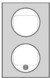
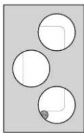
HWB-2-7Q....Adapter to convert HWB-FUL Series heated well to hold two 7-quart round pans.
HWB-2-11Q......Adapter to convert HWB-43 Series heated well to hold two 11-quart round pans.
HWB-3-4Q......Adapter to convert HWB-FUL Series heated well to hold three 4-quart round pans.
natural_image
Two circular shapes with a central dot, no text or symbols present7 Quart Round Pan Adapter Top
natural_image
Three white circles with a small shaded region, arranged on a gray background (no text or symbols)4 Quart Round Pan Adapter Top
Adapter Tops
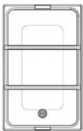
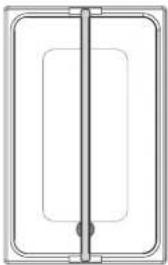
Pan Support Bars
The following pan support bars are available to divide a heated well into sections for different size pans.
HWB12BAR......12" (305 mm) Pan Support Bar
HWB20BAR ....20" (508 mm) Pan Support Bar (HWB-FUL Series only)
natural_image
Pure technical diagram of a three-tiered rectangular frame with no text, numbers, or symbols12" Pan Support Bars 20" Pan Support Ba
natural_image
Pure diagram of a rectangular frame with a vertical line and internal rectangular cutout (no text or symbols)Support Bars
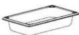
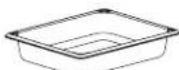
Food Pans
Stainless steel food pans are available in various sizes.
ST PAN 1/3 .... Third-size stainless steel pan — 12-3/4"W x 6-7/8"D x 2-1/2"H (324 x 175 x 64 mm)
ST PAN 1/2 ...... Half-size stainless steel pan — 12-3/4"W x 10-3/8"D x 2-1/2"H (324 x 264 x 64 mm)
ST PAN 2 ....Full size stainless steel pan at 2-1/2" (64 mm) deep — 12-3/4"W x 20-3/4"D (324 x 527 mm)
ST PAN 4 ....Full size stainless steel pan at 4" (102 mm) deep — 12-3/4"W x 20-3/4"D (324 x 527 mm)
4QT-PAN......4 quart (4 l) round pan — 6-3/4" dia x 8"H (171 x 203 mm)
7QT-PAN ...... 7 quart (7 l) round pan — 8-11/16" dia x 8"H (221 x 203 mm)
11QT-PAN .... 11 quart (10 l) round pan — 12-1/4" dia x 8"H (311 x 203 mm)
4QT-LID-1 ...... 4 quart (4 l) round, notched lid
7QT-LID-1 ..... 7 quart (7 l) round, notched lid
11QT-LID-1..... 11 quart (10 l) round, notched lid
4QT-LID.....4 quart (4 I) round, hinged and notched lid
7QT-LID.....7 quart (7 I) round, hinged and notched lid
11QT-LID.... 11 quart (10 l) round, hinged and notched lid
1/2 Pan1/3 Pan
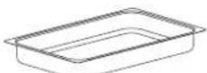
Full Pan
2-1/2" (64 mm) Deep
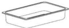
Full Pan
4" (102 mm) Deep

4 Quart (4 l)
Round Pan
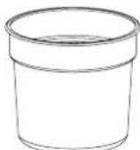
7 Quart (7 l)
Round Pan
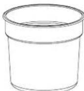
11 Quart (10 l)
Round Pan
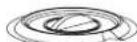
4 Quart (4 l)
Notched Lid
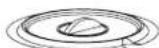
7 Quart (7 l)
Notched Lid
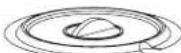
11 Quart (10 l)
Notched Lid
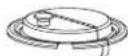
4 Quart (4 l)
Hinged Lid
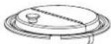
7 Quart (7 l)
Hinged Lid
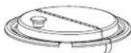
11 Quart (10 l)
Hinged Lid
Stainless Steel Food Pans
Digital Temperature Controller
A digital temperature controller is only available as an option for standard watt units equipped with a drain. Use the following procedures to operate a heated well equipped with the optional digital temperature controller.
Startup
- Move the ON/OFF (I/O) switch to the ON (I) position. The indicator light on the switch glows when the unit is on.
- The digital temperature controller will energize and the current temperature of the well or "LO" will appear on the TEMPERATURE display. "LO" indicates the well temperature is below 70^ (21°C).

BURN HAZARD: Some exterior surfaces on unit will get hot. Use caution when touching these areas.
- Press the 🔒 key three times to verify the setpoint temperature. ("SP" will be displayed after the second press.)
- The setpoint temperature will be shown for 10 seconds. After 10 seconds, the TEMPERATURE display will revert to the current temperature of the unit. To change the setpoint temperature, refer to “Changing the Setpoint Temperature” in this section.
NOTE: The digital temperature controller is factory pre-set to a setpoint temperature of 190^ F ( 88^ C) at the factory. Once the setpoint temperature is changed, the new setpoint temperature will remain in memory until it is changed again.
- Allow unit to preheat for approximately 30 minutes.
Shutdown
- Move the Power I/O (on/off) switch to the O (off) position. The indicator light on the switch will shut off.
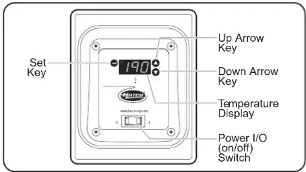
text_image
Set Key Up Arrow Key Down Arrow Key Temperature Display Power I/O (on/off) SwitchControl Enclosure with Digital Temperature Controller
Changing the Setpoint Temperature
Use the following procedure to change the setpoint temperature on a digital temperature controller.
- Press the ⚡key three times. The current setpoint temperature will be shown on the ⚡(temperature) display ("SP" will be displayed after the second press).
- Press the ▲ key or ▼ key within 10 seconds to change the setpoint temperature.
- Press the ⬤ key to lock in the new setpoint temperature. The 12 (temperature) display will go blank for two seconds to show that the new setting has been accepted.
NOTE: After 10 seconds of inactivity during the programming process, the controller will exit programming mode automatically without saving any changes.
Changing Fahrenheit and Celsius Setting
Use the following procedure to change between Fahrenheit and Celsius on the display.
- Press the ⏻ key once. Either an "F" for Fahrenheit or "C" for Celsius will be displayed.
- Press the ▲ key or ▼ key within 10 seconds to change between “F” (Fahrenheit) and “C” (Celsius).
- Press the ⏻ key three times to lock in the new setting. The 12 (temperature) display will go blank for two seconds to show that the new setting has been accepted.
NOTE: After 10 seconds of inactivity during the programming process, the controller will exit programming mode automatically without saving any changes.
WM Control
A WM controller is available as an option to replace most existing controls. Not available for Auto-fill units.
Mounting Bracket for Bottom Mount Units
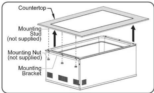
Mounting brackets for bottom mount units are available as factory-installed options (not retrofittable) for HWBIB-series. Use the following procedure to install a bottom mount unit using the mounting brackets.
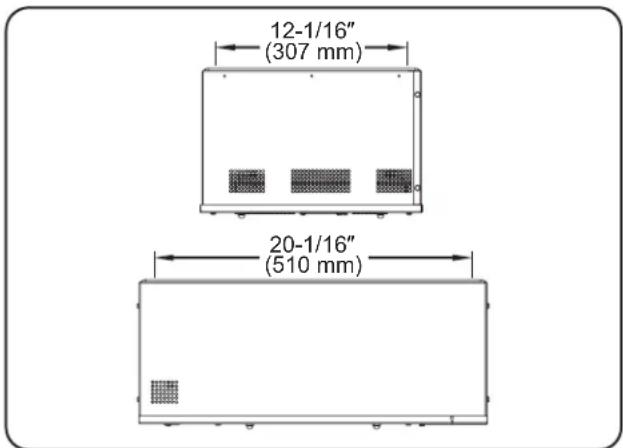
- Cut the appropriate opening into the countertop. Use the "Inside Pan Dimensions – HWBIB Models" below as a guide.
text_image
12-1/16" (307 mm) 20-1/16" (510 mm)Inside Pan Dimensions – HWBIB Models
-
Cut the appropriate opening for the control enclosure. Refer to "Control Enclosure Cutout Dimensions" in the INSTALLATION section.
-
Locate mounting studs on the underside of countertop.
- Secure the unit to the underside of the countertop.
- Apply silicone sealant to the top edge of the well before installation.
- Secure the unit to the countertop by using mounting nuts onto mounting studs through the three holes on each mounting bracket.
continued...
text_image
Countertop Mounting Stud (not supplied) Mounting Nut (not supplied) Mounting BracketInstalling Bottom Mount units using optional Mounting Brackets
Remote Drain Handle
A remote drain handle option allows easy manual drain valve shutoff. Use the following procedure to install a cabinet mounted drain handle.
-
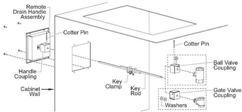
Mount the Drain Handle to the cabinet.
-
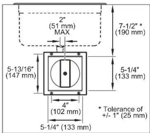
Refer to the "Remote Drain Handle Enclosure Cutout Dimensions" illustration for the appropriate cutout dimensions.
- Drain handle must have a maximum 2" (51 mm) offset from drain pipe.
- Distance from front of cabinet to center of drain must be less than 26" (660 mm).
-
Use the four screws to secure the Drain Handle enclosure to the cabinet.
-
Remove the valve handle/knob by loosening nut.
-
Units with Ball Valve: Save the nut for reuse, handle no longer needed.
- Units with Gate Valve: Save the nut for reuse, knob no longer needed.
- Install the valve coupling in place of removed valve handle or knob using the previously removed nut.
text_image
2" (51 mm) MAX 7-1/2" * (190 mm) 5-13/16" (147 mm) 5-1/4" (133 mm) 4" (102 mm) 5-1/4" (133 mm) * Tolerance of +/- 1" (25 mm)Remote Drain Handle Enclosure Cutout Dimensions
- Slide the square key rod through the handle coupling (cotter pin hole end facing up).
- Insert the cotter pin into the key rod inside the handle coupling.
- Slide the key clamp onto the key rods.
- Slide the top key rod into the valve coupling.
- Units with Gate Valve: use two shim washers inside coupling.
- Insert the cotter pin into the key rod.
- Center the key clamp on the overlapping key rods leaving a 1/8" (3 mm) gap for front to back play. Tighten both screws.
- The key rods can be installed at a 26" (660 mm) maximum distance from the front of the cabinet to the center of the drain.
- Spread both cotter pin ends to secure the rods inside the couplings.
text_image
Remote Drain Handle Assembly Handle Coupling Cabinet Wall Cotter Pin Key Clamp Key Rod Cotter Pin Ball Valve Coupling Gate Valve Coupling WashersRemote Drain Handle Installation (Cabinet Cutaway)
WARRANTY, EXCLUSIVE REMEDY:
Hatco® Corporation (Seller) warrants that the products it manufactures (Products) will be free from defects in materials and workmanship under normal use and service and when stored, maintained, and installed in strict accordance with factory recommendations. Seller's sole obligation to the person or entity buying the Products directly from Seller (Customer) under this warranty is the repair or replacement by Seller or a Seller-authorized service agency, at Seller's option, of any Product or any part thereof deemed defective upon Seller's examination, for a period of: (i) the Warranty Duration from the date of shipment by Seller or (ii) the Warranty Duration from the date of Product registration in accordance with Seller's written instructions, whichever is later. The "Warranty Duration" shall mean the specific periods set forth below for specific Product components, or, to the extent not listed below, eighteen (18) months. Credit for Products or parts returned with the prior written permission of Seller will be subject to the terms shown on Seller's material return authorization form. PRODUCTS OR PARTS RETURNED WITHOUT PRIOR WRITTEN PERMISSION OF SELLER WILL NOT BE ACCEPTED FOR CREDIT. Expenses incurred by Customer in returning, replacing, or removing the Products will not be reimbursed by Seller. If the defect comes under the terms of the limited warranty, the Products will be repaired or replaced and returned to the Customer and the cost of return freight will be paid by Seller. The remedy of repair or replacement provided for herein is Customer's exclusive remedy. Any improper use, alteration, repairs, tampering, misapplication, improper installation, application of improper voltage, or any other action or inaction by Customer or others (including the use of any unauthorized service agency) that in Seller's sole judgment adversely affects the Product shall void this warranty. The warranty expressly provided herein may only be asserted by Customer and may not be asserted by Customer's customers or other users of the Products; provided, however, that if Customer is an authorized equipment dealer of Seller, Customer may assign the warranty herein to Customer's customers, subject to all of the limitations of these Terms, and in such case, the warranty shall be exclusively controlled by Seller in accordance with these Terms. THIS LIMITED WARRANTY IS EXCLUSIVE AND IS IN LIEU OF ANY OTHER WARRANTY, EXPRESSED OR IMPLIED, INCLUDING BUT NOT LIMITED TO ANY IMPLIED WARRANTY OF NONINFRINGEMENT, MERCHANTABILITY OR FITNESS FOR A PARTICULAR PURPOSE, WHICH ARE EXPRESSLY DISCLAIMED.
One (1) Year Parts and Labor PLUS One (1) Additional Year Parts-Only Warranty:
Conveyor Toaster Elements (metal sheathed)
Drawer Warmer Elements (metal sheathed)
Drawer Warmer Drawer Rollers and Slides
Food Warmer Elements (metal sheathed)
Display Warmer Elements (metal sheathed air heating)
Holding Cabinet Elements (metal sheathed air heating)
Heated Well Elements — HW, HWB, and HWBI Series (metal sheathed)
Two (2) Year Parts and Labor Warranty:
Induction Ranges
Induction Warmers
One (1) Year Replacement Warranty:
TPT Pop-Up Toasters
One (1) Year Parts and Labor PLUS Four (4) Years
Parts-Only Warranty:
3CS and FR Tanks
One (1) Year Parts and Labor PLUS Nine (9) Years Parts-Only Warranty:
Electric Booster Heater Tanks
Gas Booster Heater Tanks
Ninety (90) Day Parts-Only Warranty:
Replacement Parts
Notwithstanding anything herein to the contrary, the limited warranty herein will not cover components in Seller's sole discretion such as, but not limited to, the following: coated incandescent light bulbs, fluorescent lights, heat lamp bulbs, coated halogen light bulbs, halogen heat lamp bulbs, xenon light bulbs, LED light tubes, glass components, and fuses; Product failure in booster tank, fin tube heat exchanger, or other water heating equipment caused by liming, sediment buildup, chemical attack, or freezing.
WARRANTY REGISTRATION INSTRUCTIONS:
Product registration must be submitted within 90 days from the date of shipment from our factory to qualify for additional coverage. Registration may be submitted through the form on Seller's website, through the form accessible through the QR code on the Product (where available), or by calling Customer Service with the required information at: 414-671-6350.
LIMITATION OF LIABILITY:
SELLER WILL NOT BE LIABLE FOR ANY INDIRECT, INCIDENTAL, CONSEQUENTIAL, PUNITIVE, EXEMPLARY, OR SPECIAL DAMAGES, INCLUDING WITHOUT LIMITATION ANY LOST PROFITS, COSTS OF SUBSTITUTE PRODUCTS, OR LABOR COSTS ARISING FROM THE SALE, USE, OR INSTALLATION OF THE PRODUCTS, FROM THE PRODUCTS BEING INCORPORATED INTO OR BECOMING A COMPONENT OF ANOTHER PRODUCT, OR FROM ANY OTHER CAUSE WHATSOEVER, WHETHER BASED ON WARRANTY (EXPRESSED OR IMPLIED) OR OTHERWISE BASED ON CONTRACT, TORT, OR ANY OTHER THEORY OF LIABILITY, AND REGARDLESS OF ANY ADVICE OR REPRESENTATIONS THAT MAY HAVE BEEN RENDERED BY SELLER CONCERNING THE SALE, USE, OR INSTALLATION OF THE PRODUCTS, EVEN IF SELLER IS AWARE OF THE POSSIBILITY OF SUCH DAMAGES. IN NO EVENT WILL SELLER'S AGGREGATE LIABILITY ARISING OUT OF OR RELATED TO THIS AGREEMENT EXCEED THE TOTAL AMOUNTS PAID TO SELLER BY CUSTOMER FOR THE PRODUCTS WITHIN THE THREE (3) MONTH PERIOD IMMEDIATELY PRECEDING THE EVENT GIVING RISE TO CUSTOMER'S CLAIM. THE LIMITATIONS SET FORTH HEREIN REGARDING SELLER'S LIABILITY SHALL BE VALID AND ENFORCEABLE NOTWITHSTANDING A FAILURE OF ESSENTIAL PURPOSE OF THE LIMITED REMEDY SPECIFIED IN THESE TERMS.
Seller reserves the right to update these Terms at any time, at its sole discretion, which become binding upon the date of publishing. For the most current version of our full Terms of Sale, see our website at: https://www.hatcocorp.com/terms-of-sale
natural_image
Technical line drawing of a rectangular enclosure with a wall-mounted pipe and control panel (no text or symbols)natural_image
Technical line drawing of a rectangular industrial device with internal components and piping (no text or symbols)natural_image
Technical line drawing of a rectangular enclosure with a curved pipe and valve attached (no text or symbols)natural_image
Technical line drawing of a rectangular enclosure with internal partitions and a connected piping outlet (no text or symbols)natural_image
Line drawing of an industrial enclosure with a piping and control panel (no text or symbols)text_image
HWB-4QTHWB-4QTD HWBI-4QTtext_image
HWB-7QTHWB-7QTD HWBI-7QTDAtext_image
HWB-11QTHWB-11QTD HWBI-11QTDAtext_image
NEMA 5-15P NEMA 5-20P NEMA 6-15PHWB-FUL HWBRN-FUL HWBRT-FUL
HWB-FULD HWBRN-FULD HWBRT-FULD
HWBL-FUL HWBLRN-FUL HWBLRT-FUL
HWBL-FULD HWBLRN-FULD HWBLRT-FULD
HWBH-FUL HWBHRN-FUL HWBHRT-FUL
HWBH-FULD HWBHRN-FULD HWBHRT-FULD
| Largeur (A) | Profonduer (B) | Hauteur (C)† |
| 347 mm(13-3/4") | 553 mm(21-3/4") | 237 mm(9-3/8") |
HWBI-FULD HWBIRT-FULD
HWBLI-FUL HWBLIRT-FUL
HWBIL-FULD HWBLIRT-FULD
HWBHI-FUL HWBHIRT-FUL
HWBHI-FULD HWBHIRT-FULD
natural_image
Technical line drawing of a rectangular electronic device with labeled dimensions B and a small inset component (no text or symbols beyond basic geometry)HWBIB-FUL HWBHIB-FUL
HWBIB-FULD HWBHIB-FULD
HWBIB-FULDA HWBHIB-FULDA
HWBLIB-FUL HWBLIBRT-FUL
HWBLIB-FULD HWBLIBRT-FULD
HWBLIB-FULDA HWBHIBRT-FUL
HWBIBRT-FUL HWBHIBRT-FULD
HWBIBRT-FULD
| Largeur (A) | Profonduer (B) | Hauteur (C) |
| 352 mm (13-7/8") | 561 mm (22-1/8") | 261 mm (10-3/8") |
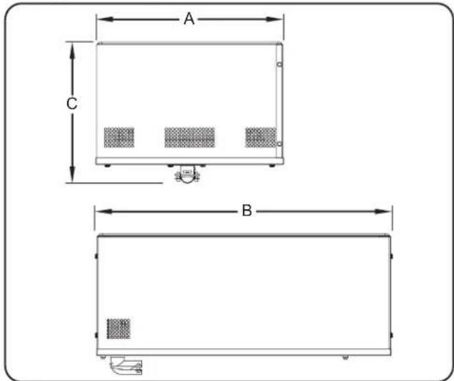
text_image
A C BHWB-43 HWB-43D HWB-43DA
HWBL-43 HWBL-43D HWBL-43DA
HWBH-43 HWBH-43D HWBH-43DA
HWBRT-43 HWBRT-43D HWBLRT-43
HWBLRT-43D HWBHRT-43 HWBHRT-43D
HWBRN-43 HWBRN-43D HWBLRN-43
HWBLRN-43D HWBHRN-43 HWBHRN-43D
| Largeur (A) | Profonduer (B) | Hauteur (C) |
| 13-5/8" (345 mm) | 28-5/8" (726 mm) | 9-7/16" (239 mm) |
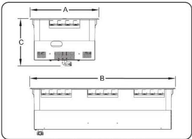
text_image
A C BHWBI-43 HWBI-43D HWBLI-43
HWBLI-43D HWBHI-43 HWBHI-43D
| Largeur (A) | Profonduer (B) | Hauteur (C) |
| 13-5/8" (345 mm) | 28-5/8" (726 mm) | 10-5/16" (262 mm) |
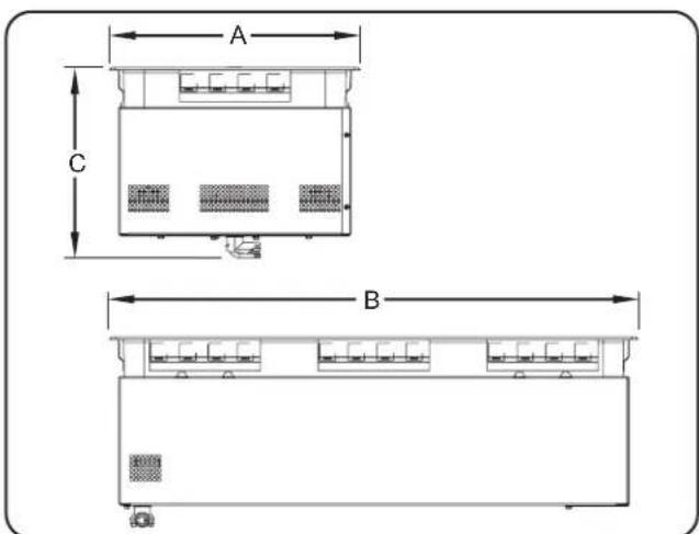
text_image
A C BUnits are voltage-specific. Refer to specification label for electrical requirements before beginning installation.
text_image
HEATED WELL HATCO CORPORATION MEASURED, MI U.S.A. www.hatco.comnatural_image
Two circular diagrams showing a rectangular object inside and a smaller rectangle with a circular base, both without any text or symbols.natural_image
Three circular diagrams with internal lines, no text or symbols presentnatural_image
Pure electrical circuit lines without any symbolsnatural_image
Pure technical diagram of a rectangular frame with internal vertical and horizontal lines, no text or symbols present.Barre de division de bacs 508 mm (20")
Barres de division de bacs
Byassee Equipment Co. Phoenix 602-252-0402
CALIFORNIA
Industrial Electric Commercial Parts & Service, Inc. Huntington Beach 714-379-7100
Chapman Appl. Service San Diego 619-298-7106
P & D Appliance Commercial Parts & Service, Inc. S. San Francisco 650-635-1900
COLORADO
Hawkins Commercial Appliance Englewood 303-781-5548
FLORIDA
Whaley Foodservice Repair Jacksonville 904-725-7800
Whaley Foodservice Repair Orlando 407-757-0851
B.G.S.I./Heritage Pompano Beach 954-971-0456
Comm. Appliance Service Tampa 813-663-0313
GEORGIA
Heritage Service Group Norcross 866-388-9837
HAWAII
Burney's Comm. Service, Inc. Honolulu 808-848-1466 Food Equip Parts & Service Honolulu 808-847-4871
ILLINOIS
Parts Town Addison 708-865-7278
Eichenauer Elec. Service Decatur 217-429-4229 Midwest Elec. Appl. Service Elmhurst 630-279-8000
Cone's Repair Service Moline 309-797-5323
IOWA
Goodwin Tucker Group Des Moines 515-262-9308
KENTUCKY
Tech 24 Lexington 859-254-8854
Tech 24 Louisville 502-451-5411
LOUISIANA
Chandlers Parts & Service Baton Rouge 225-272-6620
MARYLAND
Electric Motor Service Baltimore 410-467-8080
MASSACHUSETTS
Ace Service Co., Inc. Needham 781-449-4220
MICHIGAN
Bildons Appliance Service Detroit 248-478-3320
Commercial Kitchen Service Bay City 989-893-4561
Midwest Food Equip. Service Grandville 616-261-2000
MISSOURI
General Parts
Kansas City 816-421-5400
Commercial Kitchen Services
St. Louis 314-890-0700
Kaemmerlen Parts & Service
St. Louis 314-535-2222
NEBRASKA
Anderson Electric Omaha 402-341-1414
NEVADA
Burney's Commercial
Las Vegas 702-736-0006
Hi Tech Commercial Service
N. Las Vegas 702-649-4616
NEW JERSEY
Jay Hill Repair Fairfield 973-575-9145
Service Plus Flanders 973-691-6300
NEW YORK
Alpro Service Co. Maspeth 718-386-2515
Duffy's - AIS Buffalo 716-884-7425
3Wire Plattsburgh 800-634-5005
Duffy's - AIS Sauquoit 800-836-1014
J.B. Brady, Inc. Syracuse 315-422-9271
NORTH CAROLINA
Authorized Appliance Charlotte 704-377-4501
OHIO
Akron/Canton Comm. Svc. Inc. Akron 330-753-6634
Tech 24 Cincinnati 513-772-6600
Commercial Parts and Service Columbus 614-221-0057
Electrical Appl. Repair Service Brooklyn Heights 216-459-8700
E. A. Wichman Co. Toledo 419-385-9121
OKLAHOMA
Hagar Rest. Service, Inc. Oklahoma City 405-235-2184
OREGON
General Parts Group Portland 503-624-0890
PENNSYLVANIA
Elmer Schultz Services Philadelphia 215-627-5401
FAST Comm. Appl. Service Philadelphia 215-288-4800
AIS Commercial Parts and Service Pittsburgh 412-809-0244
K & D Service Co. Harrisburg 717-236-9039
Electric Repair Co. Reading 610-376-5444
RHODE ISLAND
Marshall Electric Co. Providence 401-331-1163
SOUTH CAROLINA
Whaley Foodservice Repair Lexington 803-996-9900
TENNESSEE
Camp Electric Memphis 901-527-7543
TEXAS
Armstrong Repair Service Houston 713-666-7100
Cooking Equipment Specialist Mesquite 972-686-6666
Commercial Kitchen Repair Co. San Antonio 210-735-2811
UTAH
La Monica's Rest. Equip. Service Murray 801-263-3221
VIRGINIA
Daubers Norfolk 757-855-4097 Daubers Springfield 703-866-3600
WASHINGTON
3Wire Seattle 800-207-3146
WISCONSIN
A.S.C., Inc. Madison 608-246-3160
A.S.C., Inc. Milwaukee 414-543-6460
CANADA
ALBERTA
Key Food Equipment Service Edmonton 780-438-1690
BRITISH COLUMBIA
Key Food Equipment Service Vancouver 604-433-4484
Key Food Equipment Service Victoria 250-920-4888
MANITOBA
Air Rite, Inc. Winnipeg 204-895-2300
NEW BRUNSWICK
EMR Services, Ltd. Moncton 506-855-4228
ONTARIO
R.G. Henderson Ltd. Toronto 416-422-5580
Choquette - CKS, Inc. Ottawa 613-739-8458
QUÉBEC
Choquette - CKS, Inc. Montreal 514-722-2000
Choquette - CKS, Inc. Québec City 418-681-3944
UNITED KINGDOM
Marren Group Northants +44(0)1933 665313
HATCO CORPORATION
P.O. Box 340500
Milwaukee, WI 53234-0500 U.S.A.
414-671-6350
support@hatcocorp.com
www.hatcocorp.com
Register your unit online!
See IMPORTANT OWNER INFORMATION
section for details.