HSBFHC3618 - Food Warmers Hatco - Free user manual and instructions
Find the device manual for free HSBFHC3618 Hatco in PDF.
Download the instructions for your Food Warmers in PDF format for free! Find your manual HSBFHC3618 - Hatco and take your electronic device back in hand. On this page are published all the documents necessary for the use of your device. HSBFHC3618 by Hatco.
USER MANUAL HSBFHC3618 Hatco
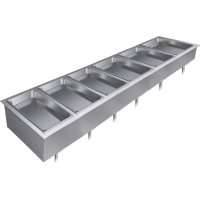
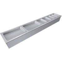
INTRODUCTION Hatco Flush Built-In Heated Shelves are designed to keep prepared foods hot while blending into the surrounding décor. Flush Built-In Heated Shelves will keep all foods at optimum serving temperatures without affecting quality. These warmers have a thermostatically-controlled heated base to extend the holding times of most foods. They are available in several sizes and in either hardcoat aluminum, simulated stone, or glass surfaces. Hatco Flush Built-In Heated Shelves are products of extensive research and field testing. The materials used were selected for maximum durability, attractive appearance, and optimum performance. Every unit is inspected and tested thoroughly prior to shipment. This manual provides the installation, safety, and operating instructions for Flush Built-In Heated Shelves. Hatco recommends all installation, operating, and safety instructions appearing in this manual be read prior to installation or operation of the unit. Safety information that appears in this manual is identified by the following signal word panels: WARNING WARNING indicates a hazardous situation which, if not avoided, could result in death or serious injury. CAUTION CAUTION indicates a hazardous situation which, if not avoided, could result in minor or moderate injury. NOTICE NOTICE is used to address practices not related to personal injury. Record the model number, serial number, voltage, and purchase date of the unit in the spaces below (specification label located on the bottom of the unit). Please have this information available when calling Hatco for service assistance. Model No. ________________________________________ Serial No. _________________________________________ Voltage ___________________________________________ Date of Purchase ___________________________________ Register your unit! Completing online warranty registration will prevent delay in obtaining warranty coverage. Access the Hatco website at www.hatcocorp.com, select the Support pull-down menu, and click on “Warranty”. Business Hours: 7:00 am to 5:00 pm Monday–Friday, Central Time (CT) (Summer Hours — June to September: 7:00 am to 5:00 pm Monday–Thursday 7:00 am to 4:00 pm Friday) Telephone: 800-558-0607; 414-671-6350 E-mail: support@hatcocorp.com 24 Hour 7 Day Parts and Service Assistance available in the United States and Canada by calling 800-558-0607. Additional information can be found by visiting our web site at www.hatcocorp.com. CONTENTSForm No. HSBFM-1121
- Plug unit into a properly grounded electrical receptacle of the correct voltage, size, and plug configuration. If plug and receptacle do not match, contact a qualified electrician to determine and install proper voltage and size electrical receptacle.
- Turn OFF power switch, unplug power cord, and allow unit to cool before performing any cleaning, adjustments, or maintenance.
- DO NOT submerge or saturate with water. Unit is not waterproof. Do not operate if unit has been submerged or saturated with water.
- Unit is not weatherproof. Locate unit indoors where ambient air temperature is a minimum of 70°F (21°C).
- Do not clean unit when it is energized or hot.
- This unit is not “jet-proof” construction. Do not use jet-clean spray to clean this unit.
- Do not steam clean or use excessive water on unit.
- Do not pull unit by power cord.
- Discontinue use if power cord is frayed or worn.
- Do not attempt to repair or replace a damaged power cord. Cord must be replaced by an Authorized Hatco Service Agent or a person with similar qualifications.
- This unit must be serviced by qualified personnel only. Service by unqualified personnel may lead to electric shock or burn.
- Remote mounted control enclosure must be mounted on a vertical wall and installed in vertical position. Mounting control enclosure in horizontal position may result in collection of liquids and lead to an electric shock.
- Use only Genuine Hatco Replacement Parts when service is required. Failure to use Genuine Hatco Replacement Parts will void all warranties and may subject operators of the equipment to hazardous electrical voltage, resulting in electrical shock or burn. Genuine Hatco Replacement Parts are specified to operate safely in the environments in which they are used. Some aftermarket or generic replacement parts do not have the characteristics that will allow them to operate safely in Hatco equipment. FIRE HAZARD: Locate unit a minimum of 1″ (25 mm) from combustible walls and materials. If safe distances are not maintained, discoloration or combustion could occur. Make sure food product has been heated to the proper food-safe temperature before placing on the unit. Failure to heat food product properly may result in serious health risks. This unit is for holding preheated food product only. Make sure all operators have been instructed on the safe and proper use of unit. This unit is not intended for use by children or persons with reduced physical, sensory, or mental capabilities. Ensure proper supervision of children and keep them away from unit. WARNING Hatco Corporation is not responsible for actual food product serving temperature. It is the responsibility of the user to ensure that food product is held and served at a safe temperature. Do not place food product directly onto hardcoat surface. Food product must be wrapped, boxed, or on a food pan. This unit has no “user-serviceable” parts. If service is required on this unit, contact an Authorized Hatco Service Agent or contact the Hatco Service Department at 800-558-0607 or 414-671-6350. CAUTION BURN HAZARD: Some exterior surfaces on unit will get hot. Avoid unnecessary contact with unit. Locate unit at proper counter height in an area that is convenient for use. The location should be strong enough to support the weight of unit and contents. Do not operate unit without control box mounted properly as described in installation instructions. Pitting or indentation in the glass surface may occur from sugary spills. If pitting or indentation occurs, the glass surface must be replaced. To prevent further damage and possible injury from broken glass, stop using unit immediately and contact an Authorized Hatco Service Agent. Make sure to clean and sanitize stone surface properly after deep cleaning the surface using abrasives and before placing food product on unit. NOTICE Do not locate unit in area with excessive air movement around unit. Avoid areas that may be subject to active air movements or currents (i.e., near exhaust fans/hoods, air conditioning ducts, and exterior doors). Do not locate unit in an area subject to excessive temperatures or grease from grills, fryers, etc. Excessive temperatures could cause damage to unit. Do not modify wiring or cut thermostat capillary on control box to increase remote mounting distance. Cutting thermostat capillary will cause unit to overheat and may damage unit as well as surrounding countertop. Do not turn on unit until it has been cleaned thoroughly. Ceramic glass surface must be clear of debris to prevent burn-on. Use only wipes, pads, and cleaners designed specifically for cleaning ceramic glass surfaces. Using other wipes, pads, or cleaners may damage ceramic glass surface. Use non-abrasive cleaners and cloths only on hardcoat and glass surfaces. Abrasive cleaners and cloths could scratch finish of unit, marring its appearance and making it susceptible to soil accumulation. Read the following important safety information before using this equipment to avoid serious injury or death and to avoid damage to equipment or property.4 Form No. HSBFM-1121 English
IMPORTANT SAFETY INFORMATION
All Models Hatco Flush Built-In Heated Shelves are ideal for server-to-customer pass-through areas, buffet/cafeteria lines, and other self-service areas. Models feature a flush top with a hardcoat aluminum, simulated stone, or glass surface. Hatco Built-In Heated Shelves are designed, manufactured, and tested to maintain safe food holding temperatures.Standard features include a Power I/O (on/off) switch with indicator light, an adjustable thermostat control, and a 6′ (1829 mm) power cord with plug. The control box is connected to the shelf with a 3′ (914 mm) conduit assembly. NOTE: Optional control cables extend the length of the standard control cables from 3′ (914 mm) to 6′ (1829 mm) or 10′ (3048 mm).Flush Built-In Heated Shelves are designed to be mounted to various types of countertop material including stainless steel, wood, Corian , and Swanstone
HSBF-HC Models HSBF-HC models are constructed with a hardcoat aluminum surface. HSBF-SS Models HSBF-SS models are constructed of a simulated stone solid surface and are available in several colors. HSBF-GL Models HSBF-GL models come standard with black glass. They are available also with white glass as a factory-installed option.Flush Built-In Heated Shelves MODEL DESIGNATION H S B F - x x - x x x x Heated ShelfBuilt-In, FlushWidth of Shelf (inches)Depth of Shelf (inches)HC = Hardcoat Surface SS = Simulated Stone SurfaceGL = Glass Surface NOTICE Do not use steel wool for cleaning. Steel wool will scratch the finish.Do not use harsh chemicals such as bleach, cleaners containing bleach, or oven cleaners to clean this unit. NOTICE Clean unit daily to avoid malfunctions and maintain sanitary operation.This unit is intended for commercial use only—NOT for household use. MODEL DESCRIPTIONForm No. HSBFM-1121
English SPECIFICATIONS Plug Configuration Units are supplied from the factory with an electrical cord and plug installed. Plugs are supplied according to the application. WARNING ELECTRIC SHOCK HAZARD: Plug unit into a properly grounded electrical receptacle of the correct voltage, size, and plug configuration. If plug and receptacle do not match, contact a qualified electrician to determine and install proper voltage and size electrical receptacle.NOTE: The specification label is located on the bottom of the unit. See the label for the serial number and verification of unit electrical information.
Top View Front View Side View
Dimensions — HSBF-GL Models Model Width (A) Depth (B) Height (C) Heated Width (D) Heated Depth (E) HSBF-GL-2418 27″ (687 mm) 21-1/8″ (537 mm) 5-3/8″ (135 mm) 23-7/8″ (607 mm) 18″ (457 mm) HSBF-GL-3018 33″ (839 mm) 29-7/8″ (759 mm) HSBF-GL-3618 39″ (992 mm) 35-7/8″ (912 mm) HSBF-GL-4818 51″ (1297 mm) 47-7/8″ (1217 mm) Dimensions8 Form No. HSBFM-1121 English INSTALLATION General Flush Built-In Heated Shelves are shipped from the factory completely assembled and ready for use. Use the following information and procedures to prepare the unit and the installation site. WARNING ELECTRIC SHOCK HAZARD:
- Plug unit into a properly grounded electrical receptacle of the correct voltage, size, and plug configuration. If plug and receptacle do not match, contact a qualified electrician to determine and install proper voltage and size electrical receptacle.
- Unit is not weatherproof. Locate unit indoors.
- Remote mounted control enclosure must be mounted on a vertical wall and installed in vertical position. Mounting control enclosure in horizontal position may result in collection of liquids and lead to an electric shock. FIRE HAZARD: Locate unit a minimum of 1″ (25 mm) from combustible walls and materials. If safe distances are not maintained, combustion or discoloration could occur. CAUTION Locate unit at proper counter height in an area that is convenient for use. The location should be strong enough to support the weight of unit and contents. NOTICE Do not locate unit in area with excessive air movement around unit. Avoid areas that may be subject to active air movements or currents (i.e., near exhaust fans/hoods, air conditioning ducts, and exterior doors). Do not locate unit in an area subject to excessive temperatures or grease from grills, fryers, etc. Excessive temperatures could cause damage to the unit. Do not turn on unit until it has been cleaned thoroughly. Ceramic glass surface must be clear of debris to prevent burn-on.
1. Remove the unit from the box.
NOTE: To prevent delay in obtaining warranty coverage, complete online warranty registration. See the IMPORTANT OWNER INFORMATION section for details.
2. Remove tape, protective packaging, and literature from all
surfaces of the unit. Installing the Unit
1. Prepare the appropriate opening in the countertop for the
unit being installed.
- Refer to the “Countertop Cutout and Mounting Bolt Dimensions” in this section.
2. Make structural modifications or add bracing underneath
the countertop to ensure the countertop will support the weight of the unit and its contents.
3. Attach a mounting bracket assembly to the underside of
the prepared countertop at each corner of the cutout. a. Align the U-shaped mounting holes on the mounting bracket with the two pre-drilled mounting holes on the underside of the countertop. The inside surface of the mounting bracket should be vertically flush with the inner surface of the countertop cutout. b. Insert appropriate fasteners through the mounting bracket and into appropriate anchoring devices in the mounting holes on the underside of the countertop. Tighten securely.
4. Install the included self-adhesive gasket around the inner,
vertical surface of the countertop cutout.
- The gasket should be positioned 1/4″ (6 mm) below the top surface of the countertop. NOTE: If the self-adhesive gasket is not available, provide a caulk backing around the inner, vertical surface of the countertop cutout 1/4ʺ (6 mm) below the top surface of the countertop. This will prevent the silicone sealant applied later in this procedure from falling through the gap between the countertop and the hot/cold shelf.
5. Carefully lower the heated shelf into the countertop cutout.
This step requires two or more people.
- The heated shelf rests on top of the four leveling bolts, which are part of the mounting bracket assembly installed at each corner of the countertop cutout.
6. Adjust the leveling bolts underneath each corner of the unit so
that the shelf is flush or slightly below the countertop surface.
7. Tighten the lock nut on each leveling bolt to secure the
8. Apply a bead of NSF-approved silicone sealant in the gap
between the countertop and the heated shelf. To apply a clean, consistent sealant bead: a. Make sure the shelf is centered in the countertop cutout. b. Install masking tape on each side of the gap to define the edge of the sealant. c. Carefully apply sealant into the gap. d. Quickly smooth the sealant surface. e. Carefully remove the masking tape before the sealant dries. NOTE: The silicone sealant must be rated for use at temperatures between -10°F (-23°C) and 250°F (121°C). CAUTION DO NOT tip unit/mounting surface after final installation. Unit is free-floating and could fall out if tipped—for permanent, horizontal installations only.Form No. HSBFM-1121
English INSTALLATION
9. Locate the remote-mounted control box assembly in
an area that is convenient for operation. If desired or necessary, the control box can be mounted in a semi- remote location.
- The control box can be panel, surface, or under counter mounted. If recess mounting, the control box will require a mounting cutout of 7-1/4″ W x 3-1/4″ H (184 x 83 mm).
- The distance the control box can be mounted from the unit is determined by the 3′ (914 mm) conduit (optional conduit lengths of 6′ [1829 mm] and 10’ [3048 mm] are also available). Do not pull the conduit tight to increase the mounting distance. The conduit should have some slack after the control box is mounted. PanelUnder CounterSurface 7-1/4″ (184 mm)
(76 mm) 3-1/4″ (83 mm) Control Box Mounting Options NOTICE Do not modify wiring or cut thermostat capillary on control box to increase-remote mounting distance. Cutting the thermostat capillary will cause the unit to overheat and may damage the unit as well as the surrounding countertop. NOTE: The remote-mounted control box should be mounted using screws with a 1/4″ (6 mm) minimum diameter screw head inserted through the keyholes located on the mounting brackets. The control box is to be readily removable, not permanently mounted.
10. Clean the heated shelf surface thoroughly in preparation
for initial operation. Refer to the MAINTENANCE section for proper cleaning procedures.
11. Plug the unit into a properly grounded electrical receptacle
R = 0.375" x 4 Mounting brackets shown for hole location reference. Holes must be pre-drilled on underside of countertop where brackets will be mounted. Model Cutout Width (A) Cutout Depth (B) Bolt Hole Location (C) Bolt Hole Location (D) Bolt Hole Location (E) Bolt Hole Location (F) HSBF-GL-2418 24-1/4″ (616 mm) 18-3/8″ (467 mm) 26″ (660 mm) 21″ (533 mm) 20-1/8″ (510 mm) 15-1/8″ (383 mm) HSBF-GL-3018 30-1/4″ (768 mm) 18-3/8″ (467 mm) 32″ (813 mm) 27″ (686 mm) 20-1/8″ (510 mm) 15-1/8″ (383 mm) HSBF-GL-3618 36-1/4″ (921 mm) 18-3/8″ (467 mm) 38″ (965 mm) 33″ (837 mm) 20-1/8″ (510 mm) 15-1/8″ (383 mm) HSBF-GL-4818 48-1/4″ (1226 mm) 18-3/8″ (467 mm) 50″ (1270 mm) 45″ (1142 mm) 20-1/8″ (510 mm) 15-1/8″ (383 mm) Countertop Cutout and Mounting Bolt Dimensions — HSBF-GL Models Countertop Cutout and Mounting Bolt Dimensions INSTALLATION12 Form No. HSBFM-1121 English General Use the following procedure to operate HSBF units. WARNING Read all safety messages in the Important Safety Information section before operating this equipment.Startup 1. Make sure the unit is plugged into a properly grounded electrical receptacle of the correct voltage, size, and plug configuration. Refer to the SPECIFICATIONS section in this manual for details. 2. Move the Power I/O (on/off) Switch to the I (on) position. CAUTION BURN HAZARD: Some exterior surfaces on unit will get hot. Use caution when touching these areas. NOTICE Do not turn on unit until it has been cleaned thoroughly. Ceramic glass surface must be clear of debris to prevent burn-on.Use only wipes, pads, and cleaners designed specifically for cleaning ceramic glass surfaces. Using other wipes, pads, or cleaners may damage ceramic glass surface.Do not slide pans across glass surface, use rough-bottomed pans, or drop anything on glass surface. Scratching or breakage may occur. Damage to glass surface or breakage of glass caused by misuse is not covered under warranty. 3. Turn the thermostat control to the desired temperature setting. • Turning the thermostat control knob clockwise will increase the temperature setting. Turning the thermostat control knob counterclockwise will decrease the temperature setting. 4. Allow the unit approximately 30 minutes to reach setpoint temperature.NOTE: Refer to the OPTIONS AND ACCESSORIES section for installation and operation information for units equipped with a flush-style remote mounted control enclosure. WARNING Hatco Corporation is not responsible for actual food product serving temperature. It is the responsibility of the user to ensure that food product is held and served at a safe temperature.Shutdown 1. Move the Power I/O Switch to the O (off) position. 2. Perform the appropriate “Daily Cleaning” procedure in the MAINTENANCE section of this manual. Power I/O SwitchTemperature Control Control Panel OPERATION General Flush Built-In Heated Shelves are designed for maximum durability and performance, with minimum maintenance. WARNING ELECTRIC SHOCK HAZARD: • Turn OFF power switch, unplug power cord, and allow unit to cool before performing any cleaning, adjustments, or maintenance. • DO NOT submerge or saturate with water. Unit is not waterproof. Do not operate if unit has been submerged or saturated with water. • Do not clean unit when it is energized or hot. • This unit is not “jet-proof” construction. Do not use jet-clean spray to clean this unit. • This unit must be serviced by qualified personnel only. Service by unqualified personnel may lead to electric shock or burn.FIRE HAZARD: Do not use harsh chemicals such as bleach (or cleaners containing bleach), oven cleaners, or flammable cleaning solutions to clean this unit.This unit has no “user-serviceable” parts. If service is required on this unit, contact an Authorized Hatco Service Agent or contact the Hatco Service Department at 800-558-0607 or 414-671-6350. NOTICE Do not use steel wool for cleaning. Steel wool will scratch the finish.Use non-abrasive cleaners and cloths only on hardcoat and glass surfaces. Abrasive cleaners and cloths could scratch finish of unit, marring its appearance and making it susceptible to soil accumulation.Do not use harsh chemicals such as bleach, cleaners containing bleach, or oven cleaners to clean this unit.Clean unit daily to avoid malfunctions and maintain sanitary operation. Daily Cleaning—HSBF-HC Models To preserve the finish and maintain operation of the unit, perform the following cleaning procedure daily. 1. Turn off the unit, unplug the power cord, and allow the unit to cool. 2. Remove and wash all food pans, if necessary. 3. Wipe down all metal surfaces with a non-abrasive, damp cloth. Stubborn stains may be removed with a good stainless steel or non-abrasive cleaner. Clean hard to reach areas using a small brush and mild soap. 4. Wipe dry all surfaces using a non-abrasive, dry cloth. MAINTENANCEForm No. HSBFM-1121
English MAINTENANCE Daily Cleaning—HSBF-SS Models Cleaning the Stone Surface Proper use of the products listed below will not damage the stone shelf (follow the directions on the product labels).NOTE: Stone surfaces are a simulated stone solid surface. CAUTION After deep cleaning stone surface using abrasives, make sure to clean and sanitize surface properly before placing food product.IMPORTANT NOTEFlush-mounted units are installed with a bead of silicone sealant between the unit and the countertop. Use caution when cleaning with the abrasive pad and avoid contact with the silicone sealant. 1. Before turning on a HSBF-SS model each day, clean and sanitize the stone surfaces using a clean, damp cloth and a sanitizer approved for food contact surfaces. If additional cleaning is necessary, refer to the following information in this section. 2. At the end of each day: a. Turn off the unit and allow to cool. b. Wipe down all metal surfaces using a clean, damp, non-abrasive cloth. c. Clean and sanitize the stone surfaces using a clean, damp cloth and a sanitizer approved for food contact surfaces. If additional cleaning is necessary, refer to the following information in this section.NOTE: To correct inconsistent staining and discoloration, refer to the following information in this section. d. Wipe dry with a clean, non-abrasive cloth. Hard to Remove Stains For hard-to-remove stains, use an abrasive pad along with an abrasive cleaner such as Ajax , Comet , Bon Ami, Magic Scrub, or Bar Keeper’s Friend . Additional abrasive pads are available from Hatco (P/N 04.39.049.00). NOTICE: Use an abrasive pad on stone surface only.NOTE: Do not use steel wool or metal scouring pads. Mineral Based Stains For a mineral-based stain, cleaners designed to remove iron or rust are recommended and should not harm the stone surface. Scratches For scratches, use sandpaper starting with the coarsest grit and going to finest grit until the scratch disappears. Blend area in with the supplied abrasive pad. Daily Cleaning—HSBF-GL Models Consistent daily cleaning will keep cleanup easy as well as protect and preserve the glass surface. Make sure to use only wipes, pads, and cleaners designed specifically for cleaning ceramic glass surfaces. 1. Before turning on the unit each day, clean the glass surface using an appropriate cleaning wipe or a damp cloth. 2. At the end of each day: a. Turn off the unit and allow to cool. b. Clean the glass surface using an appropriate cleaning wipe or damp cloth. If additional cleaning is necessary, follow the “Cleaning Burned-On Residue” procedure in this section. Cleaning Sugary/Sticky Spills To clean sugary/sticky spills, the unit should be warm while cleaning for easier removal. 1. Turn off the unit and unplug power cord. CAUTION! Burn Hazard—Heated glass will be hot. Use caution when touching this area. 2. While unit is still warm, wear an oven mitt and remove the bulk of the spill using paper towel. 3. Allow the unit to cool. 4. Follow the “Cleaning Burned-On Residue” procedure in this section to remove the remainder of the spill. 5. Do not use the unit again until the spill has been cleaned completely. CAUTION Pitting or indentation in the glass surface may occur from sugary spills. If pitting or indentation occurs, the glass surface must be replaced. To prevent further damage and possible injury from broken glass, stop using unit immediately and contact an Authorized Hatco Service Agent. Cleaning Burned-On Residue To clean burned-on residue, the use of ceramic glass cleaner may be necessary. 1. Turn off the unit, unplug power cord, and allow unit to cool. 2. Spread a few drops of ceramic glass cleaner onto the residue area. 3. Using an appropriate cleaning wipe, rub the residue area while applying pressure as needed. 4. If residue remains, repeat the steps above as needed. 5. After all residue has been removed, polish the entire glass surface using the ceramic glass cleaner and paper towel. Cleaning Metal Marks and Scratches Metal marks and scratches from pans usually can be removed. Be careful when placing pans onto the glass surface. To avoid metal marks and scratches, do not slide pans across the glass surface. 1. Turn off the unit, unplug power cord, and allow unit to cool. 2. Spread a few drops of ceramic glass cleaner onto the marked area. 3. Using an appropriate cleaning wipe, rub the marked area while applying pressure as needed. 4. If metal marks and scratches remain, repeat the steps above as needed.NOTE: Check the bottom of all pans for roughness that could scratch the glass surface.NOTE: Damage caused by sugary/sticky spills or rough pan bottoms is not covered under warranty.14 Form No. HSBFM-1121 English Symptom Probable Cause Corrective Action Unit not hot enough. Unit not allowed to preheat. Allow a minimum of 30 minutes to preheat.Temperature Control set too low. Adjust thermostat control to a higher setting.Heating element not working. Contact Authorized Service Agent or Hatco for assistance.Location of unit is susceptible to air currents (air conditioning ducts or exhaust fans).Block air currents or relocate unit. Voltage supplied is incorrect. Verify correct voltage is supplied to unit. Unit will not operate properly with low supply voltage.Unit too hot. Temperature Control set too high. Adjust thermostat control to a lower setting. Unit plugged into incorrect power supply. Verify with qualified personnel that power supply matches unit specification.Temperature Control defective. Contact Authorized Service Agent or Hatco for assistance. Voltage supplied is incorrect. Verify correct voltage is supplied to unit. High supply voltage will cause unit to overheat and my damage unit. Unit not working at all. Circuit breaker tripped. Reset circuit breaker. If circuit breaker continues to trip, contact Authorized Service Agent or Hatco.Unit not plugged in. Plug unit into proper power supply. Unit not turned on. Move Power I/O (on/off) switch to the I (on) position. Power I/O (on/off) Switch not working. Contact Authorized Service Agent or Hatco for assistance.Temperature Control not working properly. Heating element not working.Simulated stone surface material is stained, discolored, or has inconsistent staining/discoloration.Simulated stone surface is not being cleaned properly.Clean surface using the “Cleaning the Stone Surface” information in the MAINTENANCE section of this manual. If these methods fail to produce acceptable results, contact Hatco for assistance.Simulated stone shelf is flexing. Excessive weight on shelf. Distribute weight evenly on entire shelf. If weight on the shelf exceeds 50 lbs. (23 kg), a deflection up to 5/32″ (4 mm) is possible. If weight on the shelf exceeds 100 lbs. (45 kg), a deflection of 1/4″ (6 mm) is possible. The shelf is not guaranteed if weight on shelf exceeds 150 lbs. (68 kg). TROUBLESHOOTING GUIDE WARNING This unit must be serviced by qualified personnel only. Service by unqualified personnel may lead to electric shock or burn. WARNING ELECTRIC SHOCK HAZARD: Turn OFF power switch, unplug power cord, and allow unit to cool before performing any cleaning, adjustments, or maintenance. Troubleshooting Questions? If you continue to have problems resolving an issue, please contact the nearest Authorized Hatco Service Agency or Hatco for assistance. To locate the nearest Service Agency, log onto the Hatco website at www.hatcocorp.com, select the Support pull- down menu, and click on “Find A Service Agent”; or contact the Hatco Parts and Service Team at: Telephone: 800-558-0607 or 414-671-6350 e-mail: support@hatcocorp.comForm No. HSBFM-1121
OPTIONS AND ACCESSORIES
Flush Remote Mounted Control Enclosures Two flush-style remote mounted control enclosures are available — the Mechanical Temperature Control enclosure and the Digital Temperature Controller enclosure. Both enclosures are installed using the following procedure. WARNING ELECTRIC SHOCK HAZARD: Remote mounted control enclosure must be mounted on a vertical wall and installed in vertical position. Mounting control enclosure in horizontal position may result in collection of liquids and lead to an electric shock. NOTICE Install remote mounted control enclosure outside of heat zone. Locating control enclosure inside heat zone will cause control(s) to overheat, malfunction, and fail. Do not modify wiring or cut thermostat capillary on control box to increase remote mounting distance. Cutting thermostat capillary will cause unit to overheat and may damage unit as well as surrounding countertop. NOTE: A qualified electrician is recommended for connecting the units to a power source.
1. Prepare cutout and pre-drill screw holes.
a. Refer to the “Flush Remote Mounted Control Enclosure Installation Dimensions” illustration for cutout and screw hole dimensions. b. Perform the cutout and pre-drill the screw holes.
2. Remove trim cover from control enclosure assembly.
3. Position control enclosure into opening through the
4. Secure control enclosure to mounting surface using screws
5. Connect proper power source to the mounted remote
6. Reinstall trim cover.
NOTE: Units are equipped with a 3′ (914 mm) flexible conduit connecting the control enclosure to the unit. The digital temperature controller also offers 6′ (1829 mm) and 10′ (3048 mm) conduit lengths. Power I/O (on/off) Switch Both flush-style remote mounted control enclosures are equipped with a Power I/O switch. Move the Power I/O switch to the I (on) position to turn on the unit. The indicator light in the switch glows when the unit is on. Changing the Setpoint Temperature — Mechanical Temperature Control Turn the temperature control clockwise to increase the setpoint temperature. Turn the temperature control counterclockwise to decrease the setpoint temperature. Contrôle de la température Interrupteur d’alimentation I/O (marche/arrêt) Mechanical Temperature Control Mechanical Control4″ (102 mm)Digital Controller4-3/4″ (121 mm) Mounting Surface Trim Cover Control Enclosure 5-7/8″(149 mm)3-7/8″(98 mm)6-3/8″(162 mm)6-7/8″(173 mm) Side View of Installed EnclosureFront View of Cutout IMPORTANT NOTE: Make sure the installation location provides enough room for electrical connections to the control enclosure. Flush Remote Mounted Control Enclosure Installation Dimensions16 Form No. HSBFM-1121 English Changing the Setpoint Temperature — Digital Temperature Controller Units equipped with a digital temperature controller will heat up to the setpoint temperature automatically when they are turned on. Use the following procedure to change the setpoint temperature. NOTICE Built-in units must not have a setpoint temperature higher than 200°F (93°C). Temperatures exceeding 200°F will damage unit and void warranty. NOTE: The temperature shown on the display may be inaccurate when unit temperature is below 130°F (54°C).
1. Press the key three times. The current setpoint
temperature will be shown on the (temperature) display (“SP” will be displayed after the second press).
2. Press the key or key within 10 seconds to change
the setpoint temperature.
3. Press the key to lock in the new setpoint temperature.
The (temperature) display will go blank for two seconds to show that the new setting has been accepted. NOTE: After 10 seconds of inactivity during the programming process, the controller will exit programming mode automatically without saving any changes. Set Key Up Arrow Key Down Arrow Key Display Digital Temperature Controller Changing Fahrenheit and Celsius Setting — Digital Temperature Controller Use the following procedure to change between Fahrenheit and Celsius on the display.
1. Press the key once. Either an “F” for Fahrenheit or “C”
for Celsius will be displayed.
2. Press the key or key within 10 seconds to change
between “F” (Fahrenheit) and “C” (Celsius).
3. Press the key three times to lock in the new setting.
The (temperature) display will go blank for two seconds to show that the new setting has been accepted. NOTE: After 10 seconds of inactivity during the programming process, the controller will exit programming mode automatically without saving any changes. Small Control Boxes Two small-sized, flush mount control boxes are available— the Mechanical Temperature Control enclosure and the Digital Temperature Controller enclosure. Both enclosures are installed using the following procedure. WARNING ELECTRIC SHOCK HAZARD: Remote mounted control box must be mounted on a vertical wall and installed in vertical position. Mounting control box in horizontal position may result in collection of liquids and lead to an electric shock. NOTICE Do not modify wiring or cut thermostat capillary on control box to increase remote mounting distance. Cutting thermostat capillary will cause unit to overheat and may damage unit as well as surrounding countertop. Do not install remote mounted control box in an area subject to temperatures above 29°C (85°F). Excessive temperatures will cause control(s) to overheat, malfunction, and fail.
1. Prepare the small control box opening. Make sure the
control box cutout is within reach of the control box conduit from the unit. a. Refer to the “Small Control Box Installation Dimensions” illustration for cutout and screw hole dimensions. b. Perform the cutout and pre-drill the screw holes. IMPORTANT NOTE Make sure the installation location provides enough room for electrical connections to the control box.
2. Install the unit into the countertop opening:
a. Pass the small control box through the countertop opening. b. Place the unit into the countertop opening.
3. Pass the small control box through the control box opening
so it can be mounted to the front of the mounting surface.
4. Position the small control box into the cutout opening from
- Align the holes in the control box with the pre-drilled holes in the mounting surface.
5. Secure the small control box to the mounting surface using
four screws (not supplied). Power I/O (on/off) Switch Both remote mounted control boxes are equipped with a Power I/O switch. Move the Power I/O switch to the I (on) position to turn on the unit. The indicator light in the switch glows when the unit is on. OPTIONS AND ACCESSORIESForm No. HSBFM-1121
English Changing the Setpoint Temperature — Mechanical Temperature Control Turn the temperature control clockwise to increase the setpoint temperature. Turn the temperature control counterclockwise to decrease the setpoint temperature. Power I/O (on/off) SwitchTemperature Control Mechanical Temperature Control—Small Control Box Changing the Setpoint Temperature — Digital Temperature Controller Units equipped with a digital temperature controller will heat up to the setpoint temperature automatically when they are turned on. Use the following procedure to change the setpoint temperature. NOTICE Built-in units must not have a setpoint temperature higher than 200°F (93°C). Temperatures exceeding 200°F will damage unit and void warranty.NOTE: The temperature shown on the (temperature) display may be inaccurate when unit temperature is below 130°F (54°C). 1. Press the key three times. The current setpoint temperature will be shown on the (temperature) display (“SP” will be displayed after the second press). 2. Press the key or key within 10 seconds to change the setpoint temperature. 3. Press the key to lock in the new setpoint temperature. The (temperature) display will go blank for two seconds to show that the new setting has been accepted.NOTE: After 10 seconds of inactivity during the programming process, the controller will exit programming mode automatically without saving any changes. Set Key Up Arrow Key Display Down Arrow Key Power I/O (on/off) Switch Digital Temperature Controller—Small Control Box Changing Fahrenheit and Celsius Setting — Digital Temperature Controller Use the following procedure to change between Fahrenheit and Celsius on the display. 1. Press the key once. Either an “F” for Fahrenheit or “C” for Celsius will be displayed. 2. Press the key or key within 10 seconds to change between “F” (Fahrenheit) and “C” (Celsius). 3. Press the key three times to lock in the new setting. The (temperature) display will go blank for two seconds to show that the new setting has been accepted.NOTE: After 10 seconds of inactivity during the programming process, the controller will exit programming mode automatically without saving any changes. Control EnclosureSide View of Installed EnclosureMounting Surface6-3/4″(171 mm)Front View of Cutout9-7/16″(240 mm) (76 mm)Mechanical Temperature Control2-15/16″ (75 mm)Digital Temperature Controller3-1/4″ (83 mm)Mechanical TemperatureControl3-7/16″ (87 mm)Digital TemperatureController3-3/4″ (95 mm) Small Control Box Installation Dimensions
OPTIONS AND ACCESSORIES18
Form No. HSBFM-1121 English LIMITED WARRANTY WARRANTY, EXCLUSIVE REMEDY: Hatco Corporation (Seller) warrants that the products it manufactures (Products) will be free from defects in materials and workmanship under normal use and service and when stored, maintained, and installed in strict accordance with factory recommendations. Seller’s sole obligation to the person or entity buying the Products directly from Seller (Customer) under this warranty is the repair or replacement by Seller or a Seller-authorized service agency, at Seller’s option, of any Product or any part thereof deemed defective upon Seller’s examination, for a period of: (i) the Warranty Duration from the date of shipment by Seller or (ii) the Warranty Duration from the date of Product registration in accordance with Seller’s written instructions, whichever is later. The “Warranty Duration” shall mean the specific periods set forth below for specific Product components, or, to the extent not listed below, eighteen (18) months. Credit for Products or parts returned with the prior written permission of Seller will be subject to the terms shown on Seller’s material return authorization form. PRODUCTS
OR PARTS RETURNED WITHOUT PRIOR WRITTEN
PERMISSION OF SELLER WILL NOT BE ACCEPTED FOR CREDIT. Expenses incurred by Customer in returning, replacing, or removing the Products will not be reimbursed by Seller. If the defect comes under the terms of the limited warranty, the Products will be repaired or replaced and returned to the Customer and the cost of return freight will be paid by Seller. The remedy of repair or replacement provided for herein is Customer’s exclusive remedy. Any improper use, alteration, repairs, tampering, misapplication, improper installation, application of improper voltage, or any other action or inaction by Customer or others (including the use of any unauthorized service agency) that in Seller’s sole judgment adversely affects the Product shall void this warranty. The warranty expressly provided herein may only be asserted by Customer and may not be asserted by Customer’s customers or other users of the Products; provided, however, that if Customer is an authorized equipment dealer of Seller, Customer may assign the warranty herein to Customer’s customers, subject to all of the limitations of these Terms, and in such case, the warranty shall be exclusively controlled by Seller in accordance with these Terms. THIS LIMITED WARRANTY IS EXCLUSIVE AND IS IN LIEU OF ANY OTHER WARRANTY, EXPRESSED OR IMPLIED, INCLUDING BUT NOT LIMITED TO ANY IMPLIED WARRANTY OF NONINFRINGEMENT, MERCHANTABILITY, OR FITNESS FOR A PARTICULAR PURPOSE, WHICH ARE EXPRESSLY DISCLAIMED. One (1) Year Parts and Labor PLUS One (1) Additional Year Parts-Only Warranty: Conveyor Toaster Elements (metal sheathed) Drawer Warmer Elements (metal sheathed) Drawer Warmer Drawer Rollers and Slides Food Warmer Elements (metal sheathed) Display Warmer Elements (metal sheathed air heating) Holding Cabinet Elements (metal sheathed air heating) Heated Well Elements — HW, HWB, and HWBI Series (metal sheathed) Two (2) Year Parts and Labor Warranty: Induction Ranges Induction Warmers One (1) Year Replacement Warranty: TPT Pop-Up Toasters One (1) Year Parts and Labor PLUS Four (4) Years Parts-Only Warranty: 3CS and FR Tanks One (1) Year Parts and Labor PLUS Nine (9) Years Parts-Only Warranty: Electric Booster Heater Tanks Gas Booster Heater Tanks Ninety (90) Day Parts-Only Warranty: Replacement Parts Notwithstanding anything herein to the contrary, the limited warranty herein will not cover components in Seller’s sole discretion such as, but not limited to, the following: coated incandescent light bulbs, fluorescent lights, heat lamp bulbs, coated halogen light bulbs, halogen heat lamp bulbs, xenon light bulbs, LED light tubes, glass components, and fuses; Product failure in booster tank, fin tube heat exchanger, or other water heating equipment caused by liming, sediment buildup, chemical attack, or freezing. WARRANTY REGISTRATION INSTRUCTIONS: Product registration must be submitted within 90 days from the date of shipment from our factory to qualify for additional coverage. Registration may be submitted through the form on Seller’s website, through the form accessible through the QR code on the Product (where available), or by calling Customer Service with the required information at: 800-558-0607 or 414-671-6350. LIMITATION OF LIABILITY: SELLER WILL NOT BE LIABLE FOR ANY INDIRECT, INCIDENTAL, CONSEQUENTIAL, PUNITIVE, EXEMPLARY,
OR SPECIAL DAMAGES, INCLUDING WITHOUT LIMITATION
ANY LOST PROFITS, COSTS OF SUBSTITUTE PRODUCTS, OR LABOR COSTS ARISING FROM THE SALE, USE, OR INSTALLATION OF THE PRODUCTS, FROM THE
PRODUCTS BEING INCORPORATED INTO OR BECOMING
A COMPONENT OF ANOTHER PRODUCT, OR FROM ANY
FAILURE OF ESSENTIAL PURPOSE OF THE LIMITED REMEDY SPECIFIED IN THESE TERMS. Seller reserves the right to update these Terms at any time, at its sole discretion, which become binding upon the date of publishing. For the most current version of our full Terms of Sale, see our website at: https://www.hatcocorp.com/terms-of-saleFormulaire n° HSBFM-1121