
V2AH2 - Desktop computer ASUS - Free user manual and instructions
Find the device manual for free V2AH2 ASUS in PDF.
| Product Type | Desktop Computer (Barebone) |
| Brand | ASUS |
| Model | V2AH2 |
| Category | Desktop Computer |
| Dimensions (approx.) | 180 x 420 x 360 mm (W x H x D) |
| Weight (approx.) | 10 kg |
| Power Supply Input Voltage | 115 V or 230 V (selectable) |
| Power Supply Wattage (approx.) | 300 W |
| Front Panel Ports | USB 2.0 (x2), Microphone, Headphone, IEEE 1394 |
| Rear Panel Ports | PS/2 Mouse, PS/2 Keyboard, DVI, Parallel, VGA, IEEE 1394, USB 2.0 (x4 typical), Microphone, Line In, Line Out, LAN (RJ-45) |
| CPU Socket | LGA775 (compatible with Intel Pentium 4, etc.) |
| Memory Type | DDR2 DIMM |
| Expansion Slots | 1x PCIe x16, 1x PCIe x1, 2x PCI |
| Storage Bays | 1x 5.25" (optical), 1x 3.5" (floppy), 1x 3.5" (hard disk) |
| Supported Hard Drive Interface | SATA or IDE |
| Safety Features | Unplug power before installing components; handle CPU with care to avoid bent pins |
| Maintenance | Clean with dry cloth; avoid liquids; ensure proper ventilation |
| Repairability | User-replaceable CPU, memory, expansion cards, storage drives, power supply |
| Operating System | Not included |
| Color | Black |
| Material | Steel chassis, plastic front panel |
Frequently Asked Questions - V2AH2 ASUS
User questions about V2AH2 ASUS
0 question about this device. Answer the ones you know or ask your own.
Ask a new question about this device
Download the instructions for your Desktop computer in PDF format for free! Find your manual V2AH2 - ASUS and take your electronic device back in hand. On this page are published all the documents necessary for the use of your device. V2AH2 by ASUS.
USER MANUAL V2AH2 ASUS
natural_image
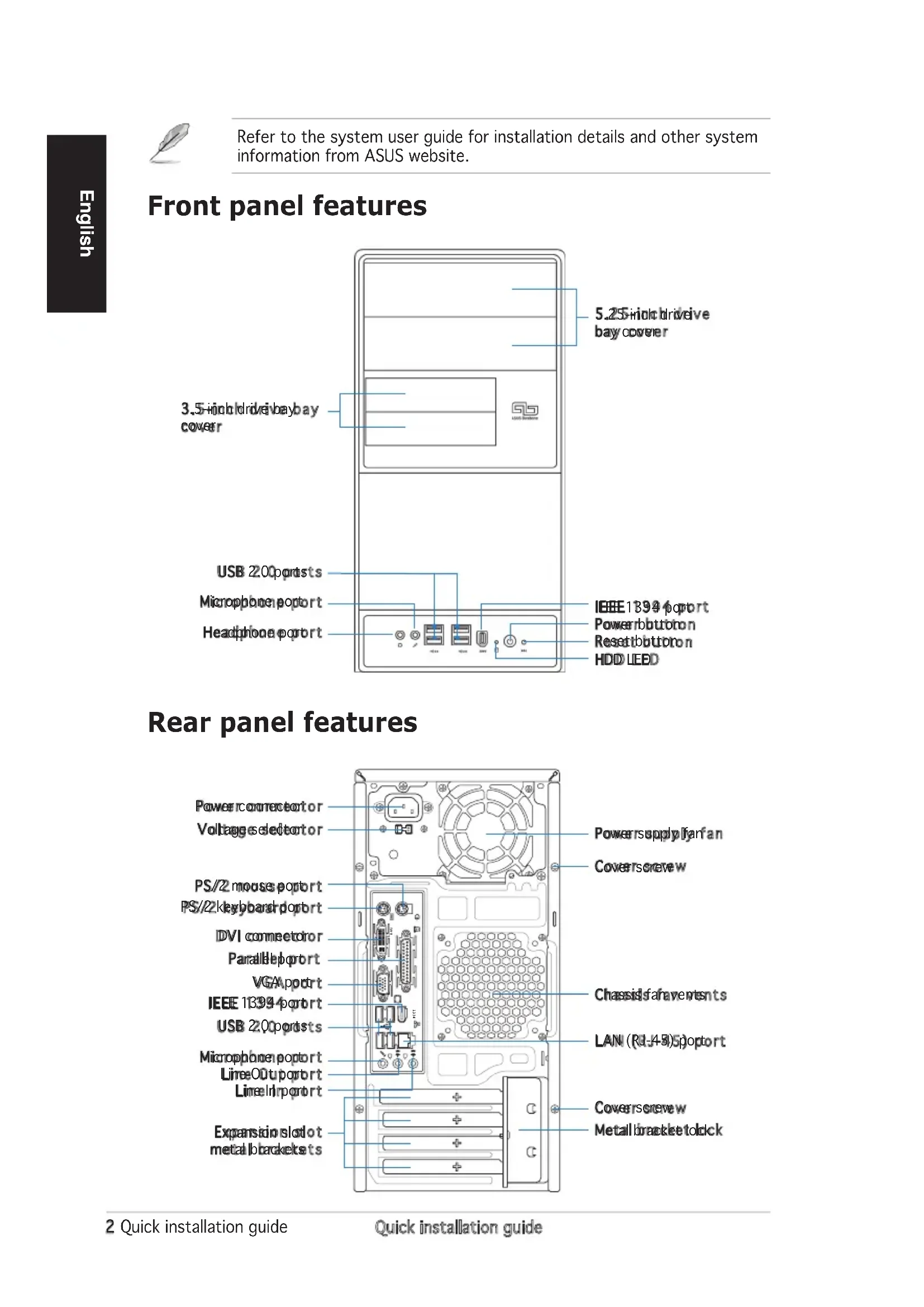
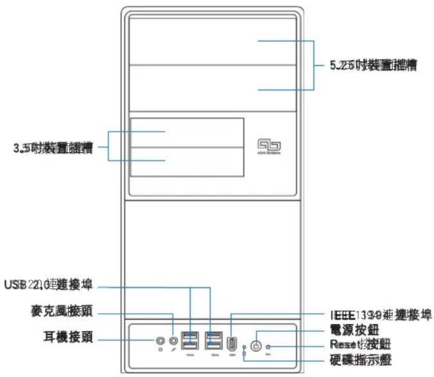
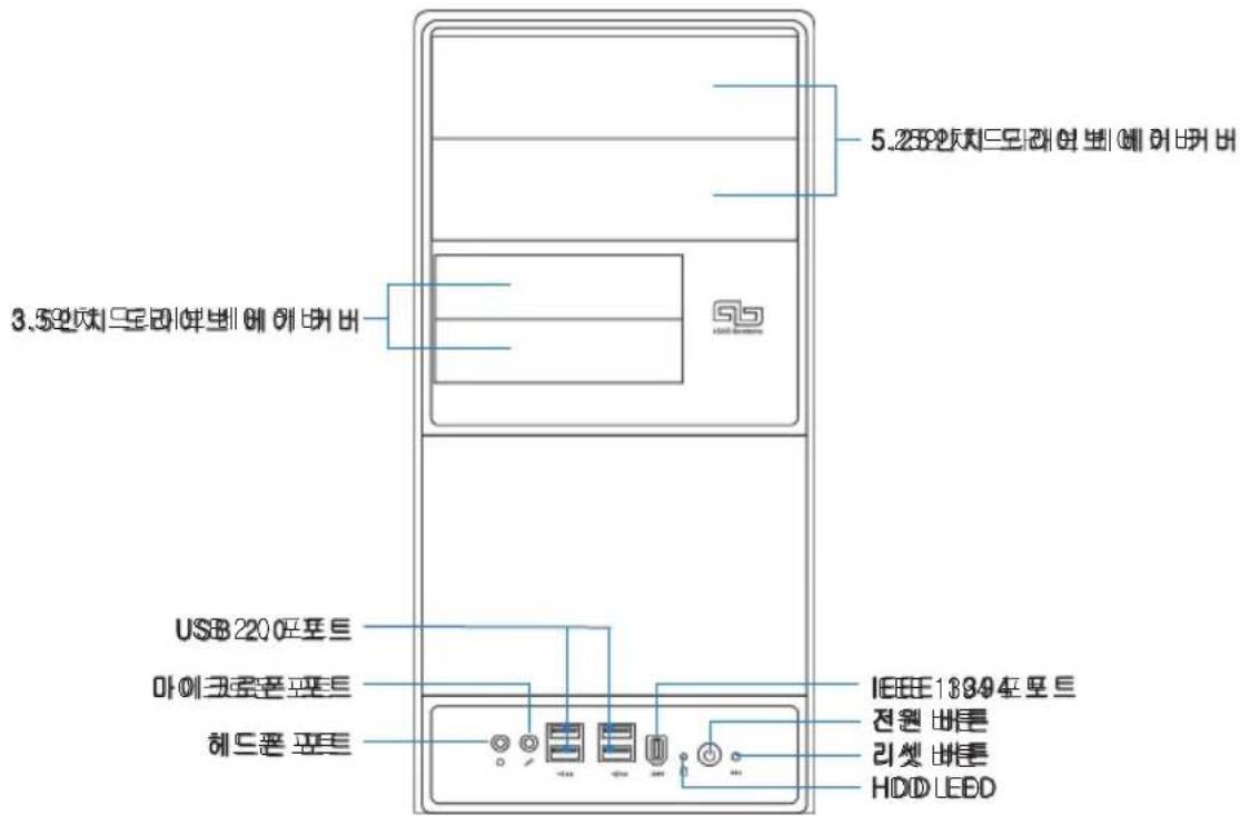
Line drawing of a desktop computer tower with labeled ports and indicators (no readable text or symbols)Front panel features

text_image
5.25-inch drive bay cover 3.5-inch drive bay bay cover USB 200 ports Microphone port Headphone port IEEE 1394 port Power button on Reset button on HDD LEDRear panel features

text_image
Power connector Voltage selector PS/2 mouse port PS/2 keyboard port DVI connector Parallel port VGA port IEEE 18394 port USB 2.0 port Microphone port Line00 port Line01 port Expansion slot metal brackets Power supply fan Coverscrew Chassis fan events LAN (Rd-149) sport Coverscrew Metall bracket to dckInternal components

text_image
Diagram of a computer tower internal structure with numbered components for identification- Front panel cover
- 5.25-inch optical drive bays
- Hard disk drive bay
- Floppy disk drive bay
- Power supply unit
- CPU socket
-
DIMM sockets
-
ASUS motherboard
- Chassis fan
- PCI Express x16 slot
- PCI Express x1 slot
- PCI slots
- Metal bracket lock
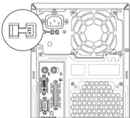
Selecting the voltage
The system's power supply unit has a 115 V/230 V voltage selector switch located beside the power connector. Use this switch to select the appropriate system input voltage according to the voltage supply in your area.
If the voltage supply in your area is 100-127 V, set the switch to 115 V.
If the voltage supply in your area is 200-240 V, set the switch to 230 V.
natural_image
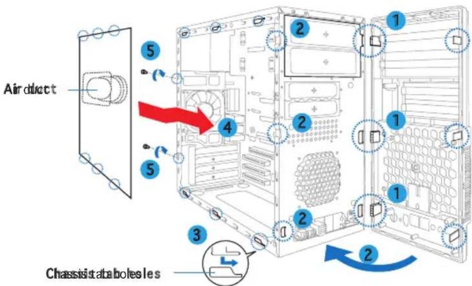
Diagram of an internal computer drive showing fan, drive bays, and ventilation slots (no text or labels)Removing the side cover and front panel assembly
- Remove the cover screws on the rear panel.
- Pull the side cover toward the rear panel until its hooks disengage from the chassis tabs. Set the side cover aside.
- Locate the front panel assembly hooks, then lift them until they disengage from the chassis.
- Swing the front panel assembly to the right, until the hinge-like tabs on the right side of the assembly are exposed.
- Remove the front panel assembly, then set aside.

text_image
Air duct 1 2 3 4 Chassis tabholes les Chassis tabholes lesInstalling a CPU
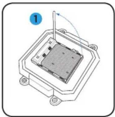
- Locate the CPU socket, then lift the socket lever to a 90°-100° angle.
- Install the CPU to the socket, making sure that the CPU corner with the gold triangle matches the socket corner with a small triangle.
- Push down the socket lever to secure the CPU.
natural_image
Diagram of a microchip or integrated circuit package with a central substrate and mounting base (no text or symbols)
natural_image
Technical diagram of a mechanical assembly with a central component and a circular annotation (no text or symbols)
natural_image
Diagram of a microchip or sensor assembly with a labeled component (3), showing internal structure and connection point (no text or symbols beyond label)
CAUTION: Incorrect installation of the CPU into the socket may bend the pins and severely damage the CPU!
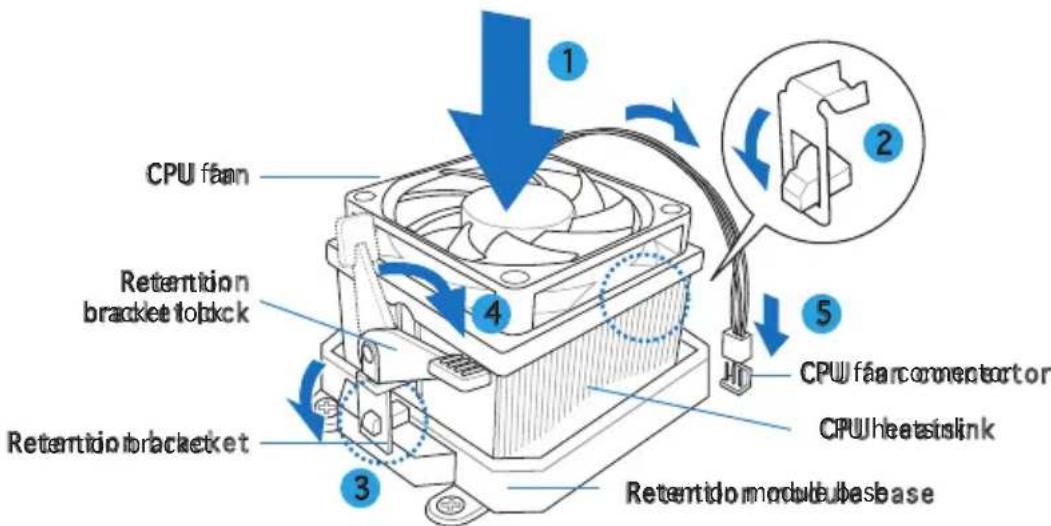
Installing the CPU fan and heatsink assembly
- Place the heatsink on top of the installed CPU.

IMPORTANT. Make sure that the fan and heatsink assembly perfectly fits the retention mechanism module base; otherwise you can not lock the retention bracket.
-
Attach one end of the retention bracket to the retention module base.
-
Attach the other end of the retention bracket (near the retention bracket lock) to the retention module base until it clicks in place.

NOTE. Your boxed CPU should come with installation instructions for the CPU, fan/heatsink assembly, and the retention mechanism. If the instructions in this section do not match the CPU documentation, follow the latter.
-
Push down the retention bracket lock on the retention mechanism to secure the fan and heatsink to the module retention module base.
-
Connect the CPU fan cable to the connector on the motherboard.

CAUTION. Do not forget to connect the CPU fan connector! Hardware monitoring error can occur if you fail to plug this connector.
text_image
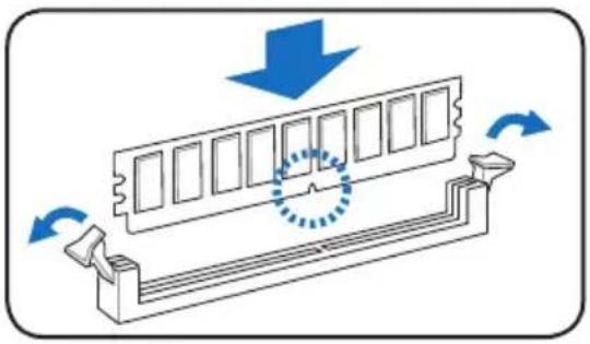
CPU fan Retention bracket to dkck Retention bracket CPU fan connector to CPU Wheat to slink Retention module base 1 2 3 4 5Installing a DIMM
-
Locate the DIMM sockets in the motherboard.
-
Unlock a DIMM socket by pressing the retaining clips outward.
-
Align a DIMM on the socket such that the notch on the DIMM matches the break on the socket.
-
Push the DIMM to the socket until the retaining clips snap inward.
natural_image
Diagram of a mechanical component with blue arrows indicating motion, showing internal structure and rotation (no text or symbols)
- Unplug the power supply before adding or removing DIMMs. Failure to do so may cause damage to the motherboard and/or components.
- A DDR2 DIMM is keyed with a notch so that it fits in only one direction. Do not force a DIMM into a socket to avoid damaging the DIMM.
Installing an expansion card
- Remove the metal bracket lock.
- Remove the metal cover opposite the slot that you intend to use.
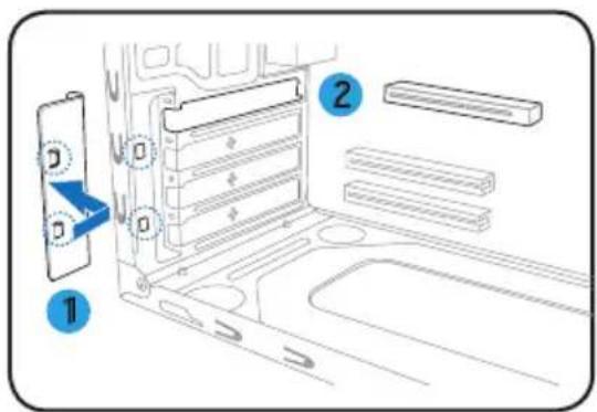
text_image
Diagram showing a device panel with labeled components and directional arrows, likely illustrating a mechanical or electronic assembly.- Insert the card connector to the slot, then press the card firmly until it fits in place.
- Replace the metal bracket lock.

text_image
Diagram showing a device with labeled components and directional arrows, including numbered parts 3 and 4.Installing storage drives
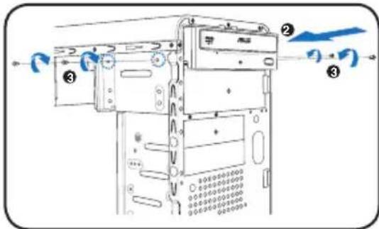
Optical drive
- Place the chassis upright, then remove the upper 5.25" drive bay metal plate cover.
- Insert the optical drive to the bay, then carefully push the drive until its screw holes align with the holes on the bay.
- Secure the optical drive with two screws on both sides of the bay.
- Connect the IDE (A) and power (B) plugs to connectors at the back of the drive.
text_image
Diagram of a refrigerator with labeled parts and directional arrows indicating airflow or movement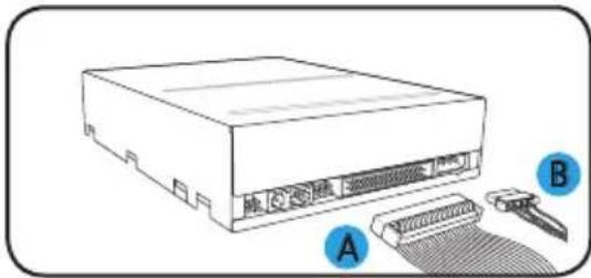
natural_image
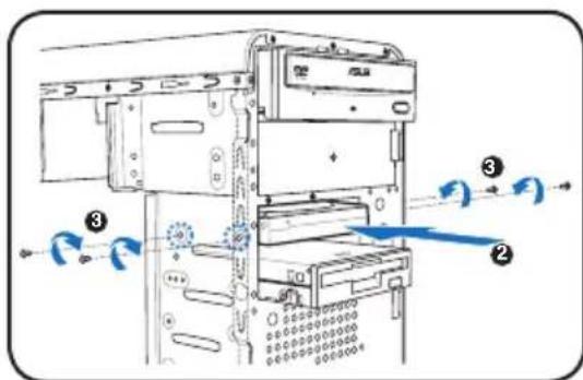
Line drawing of a computer drive with labeled ports A and B, showing internal components and cable attachment (no text or symbols beyond labels)Floppy disk drive
- Place the chassis upright, then remove the lower 3.5" drive bay metal plate cover.
- Insert the floppy disk drive to the bay, then carefully push the drive until its screw holes align with the holes on the bay.
- Secure the floppy disk drive with two screws on both sides of the bay.
- Connect the signal (A) and power (B) plugs to connectors at the back of the drive.
text_image
Technical diagram of a computer tower with numbered components and directional arrows indicating flow or movement.
text_image
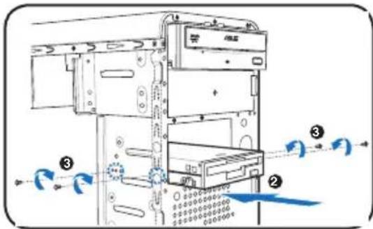
Diagram showing a computer drive with labeled components A and B, indicating internal structure and cable connection.Hard disk drive
- Place the chassis upright, then remove the upper 3.5" drive bay metal plate cover.
- Insert the hard disk drive to the bay, then carefully push the drive until its screw holes align with the holes on the bay.
- Secure the hard disk drive with two screws on both sides of the bay.
text_image
Technical diagram of a device with numbered components and directional arrows indicating flow or movement- For SATA HDD Connect the SATA signal and power plugs to the connectors at the back of the drive.
For IDE IHDConnect the IDE signal and power plugs to the connectors at the back of the drive

text_image
SATA IDATA IDERemoving the bay covers and reinstalling the front panel assembly and side cover
If you installed an optical and/or floppy disk drive, remove the bay cover(s) on the front panel assembly before reinstalling it to the chassis. To do this:
- Locate the bay cover locks.
- Press the locks outward to release the bay cover.
- Push the bay cover inward, then set it aside.
- Follow the same instructions to remove the 3.5" drive bay cover.

natural_image
Diagram of a device interior with blue directional arrows indicating flow or movement (no text or symbols)To reinstall the front panel assembly and side cover:
- Insert the front panel assembly hinge-like tabs to the holes on the right side of the chassis.
- Swing the front panel assembly to the left, then insert the hooks to the chassis until the front panel assembly fits in place.
- Insert the side cover hooks to the chassis top and bottom holes.
- Push the side cover to the direction of the front panel until it fits in place.
- Secure the cover with two screws you removed earlier.
text_image
Air duct 5 4 2 1 2 1 3 Chassis Bahamasles 2ASUS®
Vintage V2-AH2
Système barebone
natural_image
Line drawing of a desktop computer tower case with front panel, drive buttons, and ventilation unit (no text or symbols)text_image
Diagram of a computer tower internal structure with numbered components for identificationnatural_image
Diagram of a microchip or integrated circuit package with a central component and mounting base (no text or symbols)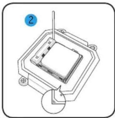
natural_image
Technical diagram of a mechanical assembly with a central component and a circular annotation labeled '2' (no text or symbols on the diagram itself)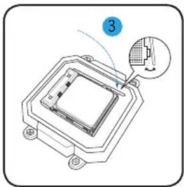
natural_image
Technical diagram of a microchip or sensor assembly with a magnified inset showing a component detail (no text or symbols present)
natural_image
Diagram of a mechanical component with blue arrows indicating motion, showing a circular motion around its edge (no text or symbols)
text_image
Diagram of a computer drive bay with labeled components and directional arrows indicating movement or flow.
text_image
Diagram showing a device with labeled components and directional arrows, including numbered parts 3 and 4.text_image
Diagram of a device with labeled components and directional arrows indicating flow or movement
text_image
A Btext_image
Technical diagram of a computer tower with numbered components and directional arrows indicating motion or flow.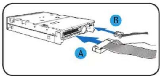
text_image
Diagram showing a computer drive with labeled components A and B, indicating internal structure and cable connection.text_image
Technical diagram of a device with numbered components and directional arrows indicating flow or movementnatural_image
Diagram of a device interior with blue arrows indicating flow or movement, no text or symbols presentnatural_image
Line drawing of a desktop computer tower with labeled ports and indicators (no text or symbols on the main body)前面板功能
text_image
Diagram of a computer tower internal structure with numbered components for identificationnatural_image
Diagram of a microchip or integrated circuit with a central component and mounting base (no text or symbols)
natural_image
Technical diagram of a mechanical assembly with a central square component and a circular inset showing a pin (no text or symbols)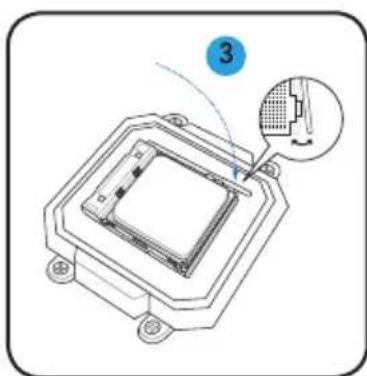
natural_image
Diagram of a microchip or sensor assembly with a highlighted component and label '3' (no text or symbols on the diagram itself)
natural_image
Diagram of a mechanical component with directional arrows indicating motion or force, no text or symbols present.
text_image
Diagram of a device rear panel with labeled components and directional arrows indicating movement or flow.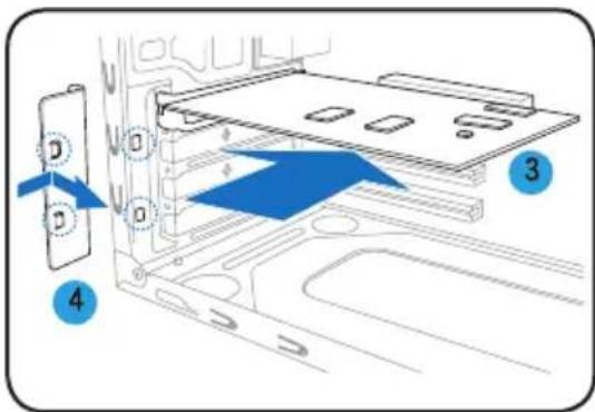
text_image
Diagram showing a device with labeled components and directional arrows, including numbered parts 3 and 4.安裝儲存裝置
光碟機
text_image
Diagram of a refrigerator with labeled parts and directional arrows indicating airflow or movement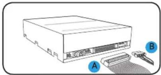
text_image
地記電源 A B軟碟機
text_image
Technical diagram of a computer tower with numbered components and directional arrows indicating flow or movement.
text_image
Diagram showing a computer drive with labeled components A and B, indicating internal structure and cable connection.硬碟機
text_image
Technical diagram of a device with numbered components and directional arrows indicating motion or flowtext_image
SAT A ISATA IDE移除裝置擋板並裝回機殼側板及前面板
natural_image
Line drawing of a desktop computer tower with front panel, drive bays, and indicator lights (no text or symbols)前面板功能

text_image
Diagram of a computer tower rear panel with numbered components for identificationnatural_image
Diagram of a mechanical assembly with a central component and surrounding mounting holes (no text or symbols)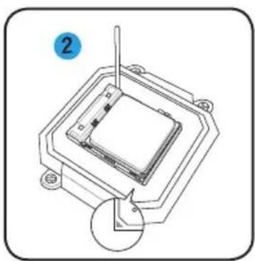
natural_image
Technical line drawing of a mechanical assembly with a central component and mounting base (no text or symbols)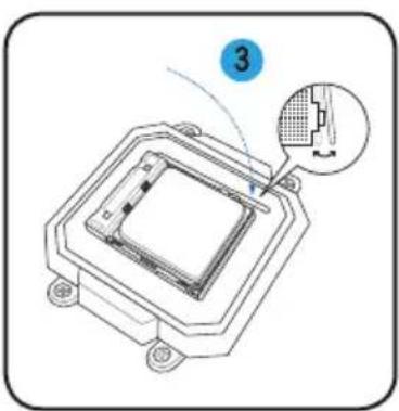
natural_image
Diagram of a microchip or integrated circuit package with a close-up inset showing internal components (no text or symbols)
natural_image
Diagram of a mechanical component with blue arrows indicating motion, showing internal structure and rotation (no text or symbols)
text_image
Diagram of a device rear panel with labeled components and directional arrows indicating movement or flow.text_image
Diagram showing a device with labeled components and directional arrows, including numbered parts 3 and 4.安装存储设备
光驱
text_image
Diagram of a refrigerator with labeled parts and directional arrows indicating airflow or movement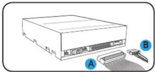
text_image
地記電源 A B软驱
text_image
Technical diagram of a computer tower with numbered components and directional arrows indicating motion or flow.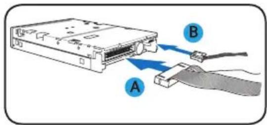
text_image
Diagram showing a computer drive with labeled components A and B, indicating internal structure and cable connection.硬盘
text_image
Technical diagram of a device with numbered components and directional arrows indicating motion or flownatural_image
Diagram of a device interior with blue arrows indicating flow or movement, no text or symbols present请依照以下步骤装回机箱侧板及前面板:
natural_image
Line drawing of a desktop computer tower case with front panel, drive buttons, and ventilation unit (no text or symbols)フロントパネルの機能

text_image
Diagram of a computer tower internal structure with numbered components for identificationnatural_image
Diagram of a computer tower rear panel showing internal components and a magnified inset of the IIS device (no text or symbols present)サイドカバーとフロントパネルを取り外す
natural_image
Diagram of a mechanical component with a central housing and mounting base, showing a rotation arrow (no text or symbols)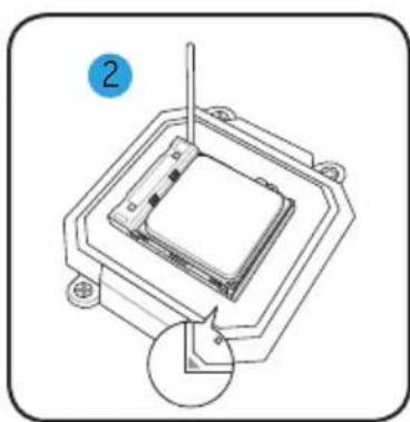
natural_image
Technical diagram of a mechanical assembly with a central component and a circular inset view (no text or symbols)
natural_image
Diagram of a microchip or sensor assembly with a magnified inset showing internal structure (no text or symbols)
natural_image
Diagram of a mechanical component with directional arrows indicating motion or flow (no text or symbols)
text_image
Diagram of a device rear panel with labeled components and directional arrows indicating movement or flow.text_image
Diagram of a computer drive with labeled components and directional arrows indicating movement or assembly.記憶ドライブを取り付ける
光学ドライブ
text_image
Diagram of a device interior with labeled parts and directional arrows indicating flow or movement.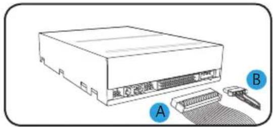
text_image
A Bフロッピーディスクドライブ (FDD)
text_image
Technical diagram of a computer tower with numbered components and directional arrows indicating motion or flow.
text_image
Diagram showing a computer drive with labeled components A and B, indicating internal structure and cable connection.ハードディスクドライブ(HDD)
text_image
Technical diagram of a device with numbered components and directional arrows indicating flow or movementnatural_image
Diagram of a device's internal structure with blue arrows indicating flow or movement, no text or symbols presentフロントパネルとサイドカバーを戻す
natural_image
Line drawing of a desktop computer tower with front panel, drive buttons, and ventilation slots (no text or symbols)전면부 사양
text_image
5.28ΩΩΩΩΩΩΩΩΩΩΩΩΩΩΩΩΩΩΩΩΩΩΩΩΩΩΩΩΩΩΩΩΩΩΩΩΩΩΩΩΩΩΩΩΩΩΩΩΩΩΩΩΩΩΩΩΩΩΩΩΩΩΩΩΩΩΩΩΩΩΩΩΩΩΩΩΩΩΩΩΩΩΩΩΩΩΩΩΩΩΩΩΩΩΩΩΩΩΩΩ 3.5ΩΩΩΩΩΩΩΩΩΩΩΩΩΩΩΩΩΩΩΩΩΩΩΩΩΩΩΩΩΩΩΩΩΩΩΩΩΩΩΩΩΩΩΩΩΩΩΩΩΩΩΩΩ USB 220 port 마이크로운 풀트 헤드폰 풀트 IEEE18394 port 전원 비론 리셋 비론 HDD LED후면부 사양

text_image
Diagram of a computer tower internal structure with numbered components for identificationnatural_image
Diagram of a computer tower rear panel showing internal components like CPU socket, drive bays, and ventilation fan (no text or labels)케이스 측면판과 전면부 패널 제거
natural_image
Diagram of a microchip or integrated circuit package with a central component and mounting base (no text or symbols)
natural_image
Technical diagram of a mechanical assembly with a central component and a circular inset view (no text or symbols)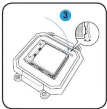
natural_image
Diagram of a microchip or sensor assembly with a labeled component (3), showing internal structure and a close-up inset view (no text or symbols present)
natural_image
Diagram of a mechanical component with arrows indicating motion, showing a circular motion around its edge (no text or symbols present)
text_image
Diagram showing a device interior with labeled parts and directional arrows, likely illustrating a mechanical or electronic component layout.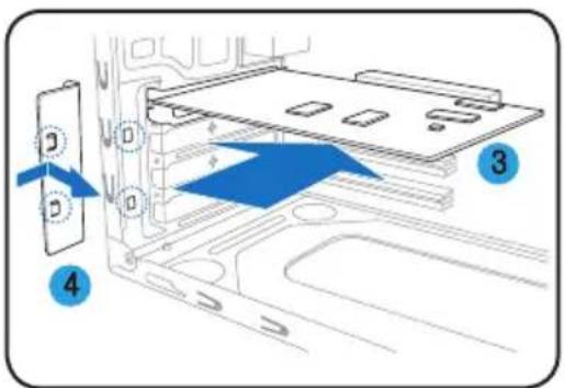
text_image
Diagram showing a device with labeled components and directional arrows indicating movement or flow, marked as 3 and 4.저장 드라이브 설치
ODD
text_image
Technical diagram of a device with labeled components and directional arrows indicating flow or movement.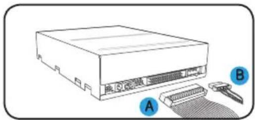
text_image
电源 A B플로피 디스크 드라이브
text_image
Technical diagram of a computer tower with numbered components and directional arrows indicating movement or flow.
text_image
Diagram showing a computer drive with labeled components A and B, indicating cable or connector connection.하드디스크 드라이브
text_image
Diagram of a computer tower with labeled components and directional arrows indicating flow or movement.text_image
SATA I/O SATA IDEnatural_image
Diagram of a door frame with blue directional arrows indicating movement or flow (no text or symbols)natural_image
Line drawing of a desktop computer tower with front panel, drive bays, and indicator lights (no text or symbols)
text_image
Diagram of a computer tower rear panel with numbered components for identificationnatural_image
Diagram of a computer tower rear panel showing internal components like CPU socket, drive fuses, and ventilation fan (no text or labels)natural_image
Technical diagram of a mechanical component with a central square base and mounting holes, no visible text or symbols
natural_image
Technical diagram of a mechanical assembly with a central component and a circular annotation (no text or symbols)
natural_image
Technical line drawing of a microchip or sensor assembly with a magnified inset showing a component detail (no text or symbols present)
natural_image
Diagram of a mechanical component with directional arrows indicating motion, no text or symbols present
text_image
Diagram of a computer drive bay with labeled components and directional arrows indicating movement or flow.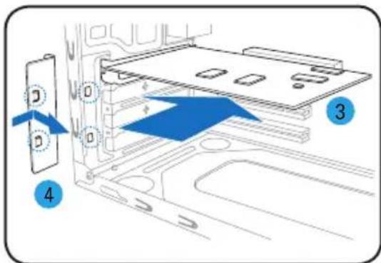
text_image
Diagram showing a device with labeled components and directional arrows, including numbered parts 3 and 4.text_image
Diagram of a refrigerator interior with labeled parts and directional arrows indicating movement or flow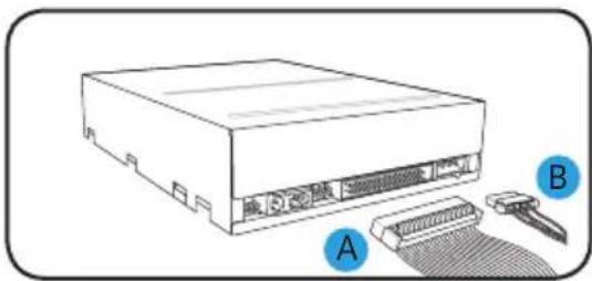
natural_image
Illustration of a computer drive with labeled components A and B, showing internal components and a connector (no text or symbols beyond labels)text_image
Diagram of a computer tower with labeled components and directional arrows indicating flow or movement