
V2M3A3200 - Desktop computer ASUS - Free user manual and instructions
Find the device manual for free V2M3A3200 ASUS in PDF.
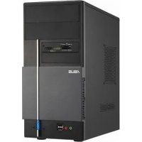



| Product type | Desktop computer (barebone) |
| Brand | Asus |
| Model | V2M3A3200 |
| Power supply | Power supply with voltage selector 115 V/230 V |
| Supported processors | Intel Pentium 4 (LGA775) or AMD (appropriate socket) |
| Memory type | DDR DIMM |
| Drive bays | 1 x 5.25" bay (optical drive), 2 x 3.5" bays (floppy drive and hard drive) |
| Front connectors | USB 2.0 ports, audio ports (headphone, microphone), power and reset buttons |
| Rear connectors | PS/2 keyboard/mouse ports, VGA, parallel, USB 2.0, LAN RJ-45, optional E-SATA, serial, DVI, S/PDIF, IEEE 1394a, 6/8 channel audio |
| Dimensions (approx.) | Height: 40 cm, Width: 18 cm, Depth: 45 cm |
| Weight (approx.) | 8 kg |
| Main functions | CPU, memory, expansion cards, storage drives installation; voltage configuration |
| Maintenance and cleaning | Disconnect power before any intervention; use a dry cloth for external cleaning |
| Safety | Do not force components; avoid contact with processor pins; respect voltages |
| Spare parts and repairability | ASUS motherboard, power supply, fans, covers, screws; standard compatible parts |
| General information | V series desktop computer; installation manual included |
Frequently Asked Questions - V2M3A3200 ASUS
User questions about V2M3A3200 ASUS
0 question about this device. Answer the ones you know or ask your own.
Ask a new question about this device
Download the instructions for your Desktop computer in PDF format for free! Find your manual V2M3A3200 - ASUS and take your electronic device back in hand. On this page are published all the documents necessary for the use of your device. V2M3A3200 by ASUS.
USER MANUAL V2M3A3200 ASUS
ASUS PC (Desktop Barebone)
Installation manual
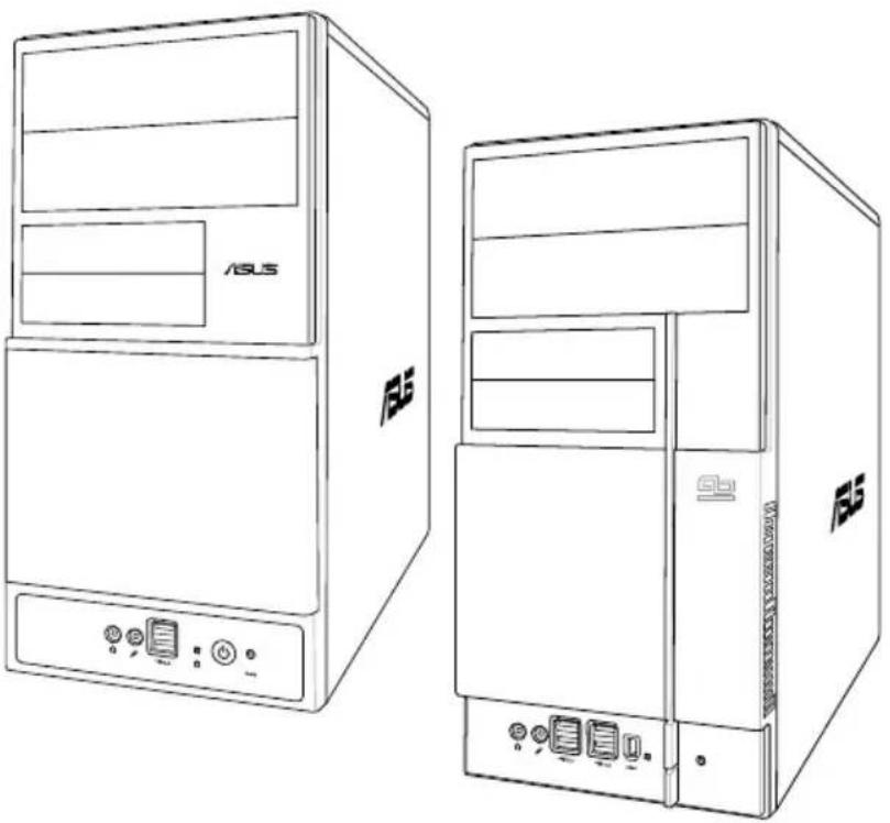
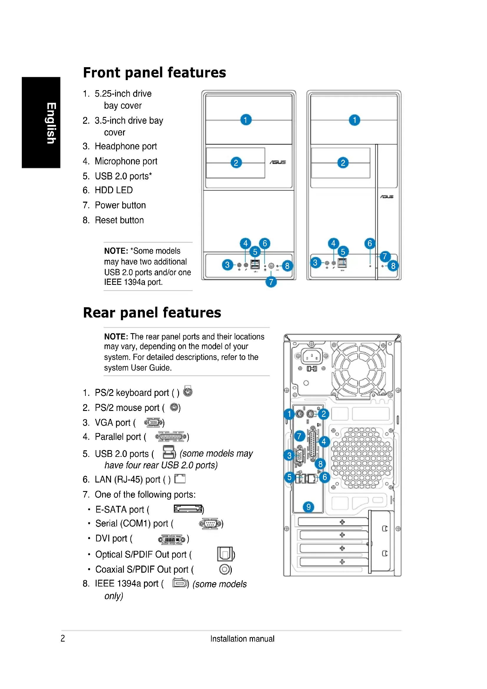
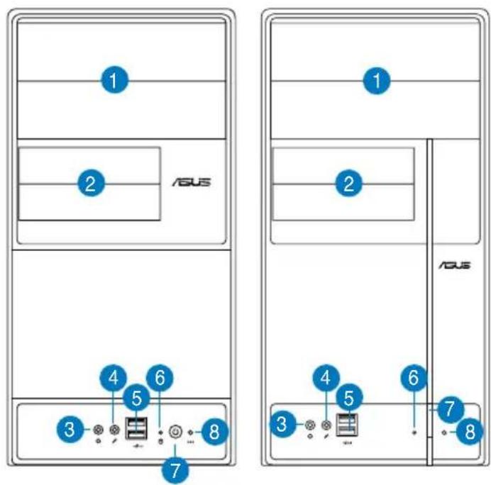
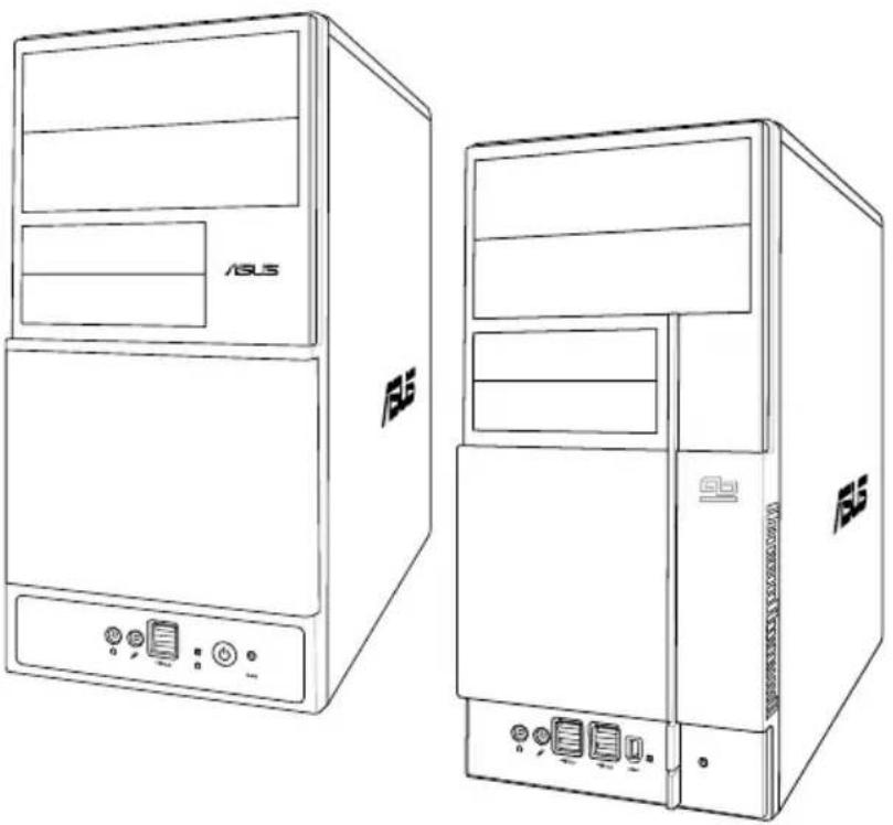
Front panel features
- 5.25-inch drive bay cover
- 3.5-inch drive bay cover
- Headphone port
- Microphone port
- USB 2.0 ports*
- HDD LED
- Power button
- Reset button
NOTE: *Some models may have two additional USB 2.0 ports and/or one IEEE 1394a port.
Rear panel features
NOTE: The rear panel ports and their locations may vary, depending on the model of your system. For detailed descriptions, refer to the system User Guide.
- PS/2 keyboard port ( )
- PS/2 mouse port (Ⓞ)
- VGA port ( )
- Parallel port ( )
- USB 2.0 ports ( ) (some models may have four rear USB 2.0 ports)
- LAN (RJ-45) port ()
- One of the following ports:
• E-SATA port ( ) • Serial (COM1) port ( ) • DVI port ( ) • Optical S/PDIF Out port ( ) • Coaxial S/PDIF Out port ( )
- IEEE 1394a port ( ) (some models only)
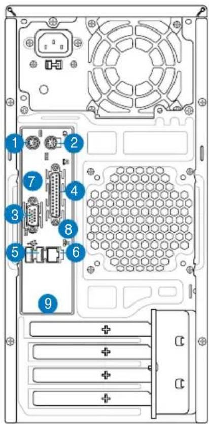
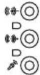
- One of the following audio port configurations:
- 6-channel
• 8-channel
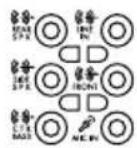
Refer to the configuration table in the User Guide for details.
Internal components
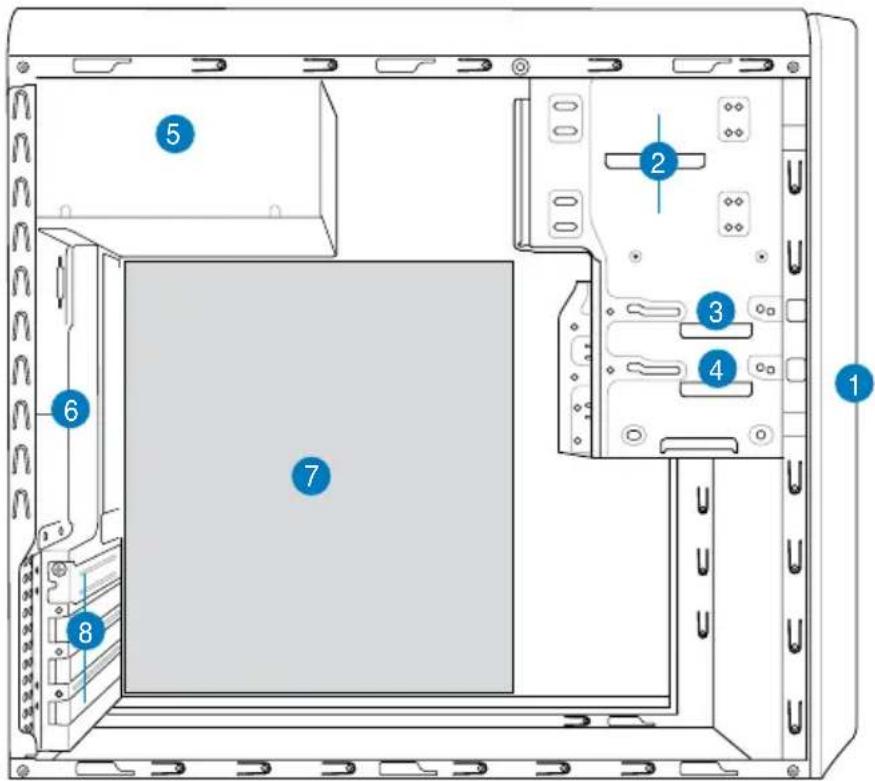
- Front panel cover
- 5.25-inch optical drive bays
- Floppy disk drive bay
- Hard disk drive bay
- Power supply unit
- Chassis fan slot
- ASUS motherboard*
- Expansion slot metal brackets
NOTE: *Refer to the system User Guide for motherboard details.
Selecting the voltage
The system's power supply unit has a 115 V/230 V voltage selector switch located beside the power connector. Use this switch to select the appropriate system input voltage according to the voltage supply in your area.
If the voltage supply in your area is 100-127 V, set the switch to 115 V.
If the voltage supply in your area is 200-240 V, set the switch to 230 V.
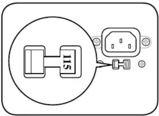
NOTE: Refer to the system User Guide for the exact location of the voltage selector.
Removing the side cover and front panel assembly
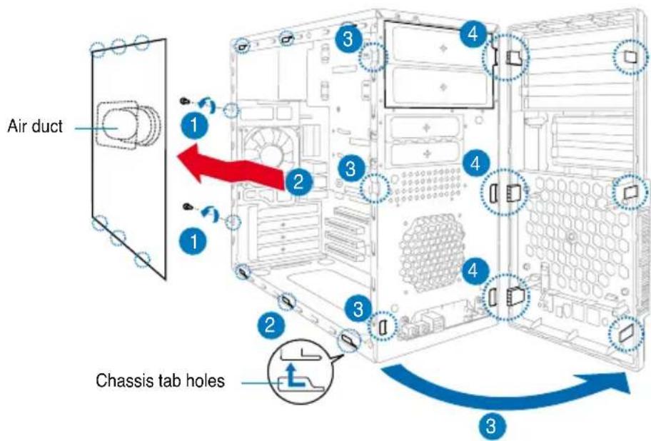
- Remove the cover screws on the rear panel.
- Pull the side cover toward the rear panel until its hooks disengage from the chassis tab holes. Set the side cover aside.
- Locate the front panel assembly hooks, then lift them until they disengage from the chassis.
- Swing the front panel assembly to the right, until the hinge-like tabs on the right side of the assembly are exposed.
- Remove the front panel assembly, then set aside.
Installing a CPU
Installing an Intel® Pentium® 4 CPU in the LGA775 package
- Locate the CPU socket on the motherboard.
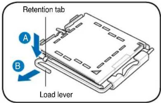
- Press the load lever with your thumb (A), then move it to the left (B) until it is released from the retention tab.
CAUTION. To prevent damage to the socket pins, do not remove the PnP cap unless you are installing a CPU.
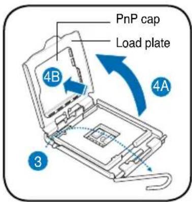
- Lift the load lever in the direction of the arrow to a 135° angle.
- Lift the load plate with your thumb and forefinger to a 100° angle (4A), then push the PnP cap from the load plate window to remove (4B).
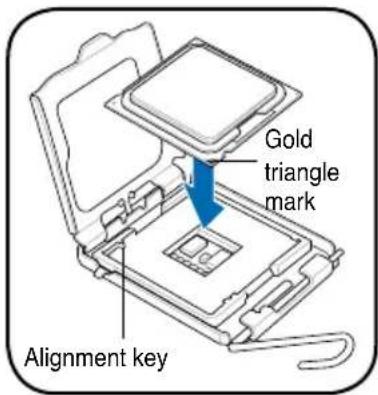
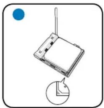
- Position the CPU over the socket, making sure that the gold triangle is on the bottom-left corner of the socket. Fit the socket alignment key into the CPU notch.
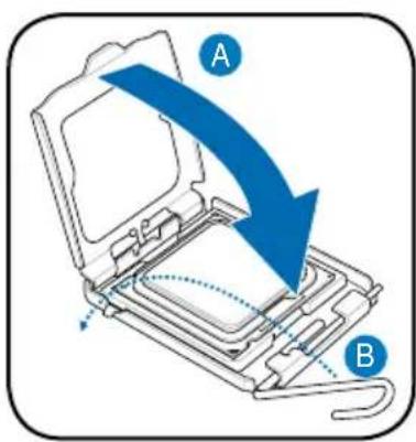
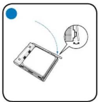
- Close the load plate (A), then push the load lever (B) until it snaps into the retention tab.
Installing an AMD CPU
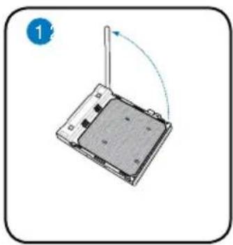
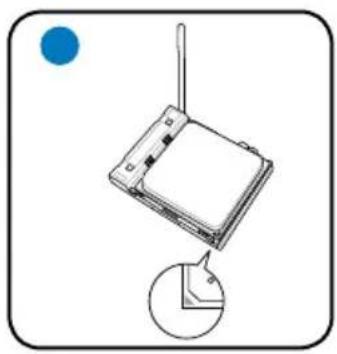
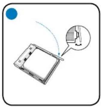
- Locate the CPU socket, then lift the socket lever to a 90° angle.
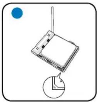
- Install the CPU to the socket, making sure that the CPU corner with the gold triangle matches the socket corner with a small triangle.
- Push down the socket lever to secure the CPU.
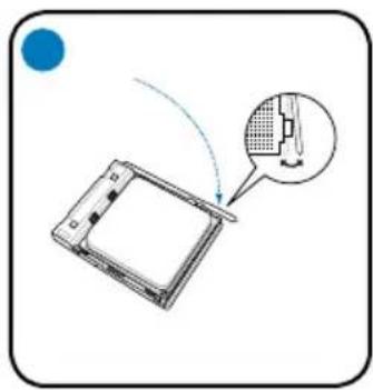
CAUTION: Incorrect installation of the CPU into the socket may bend the pins and severely damage the CPU!
Installing the CPU fan and heatsink assembly Installing an Intel® Pentium® 4 CPU heatsink and fan
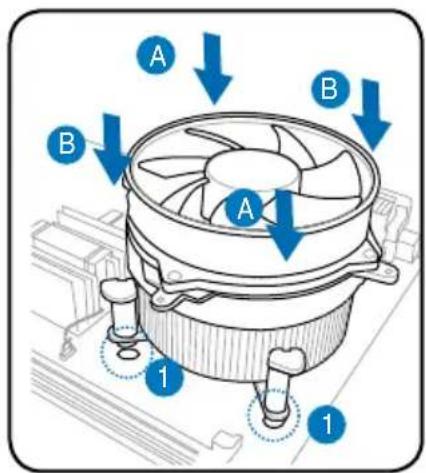
- Place the heatsink on top of the installed CPU, making sure that the four fasteners match the holes on the motherboard.
- Push down two fasteners at a time in a diagonal sequence to secure the heatsink and fan assembly in place.
- When the fan and heatsink assembly is in place, connect the CPU fan cable to the connector on the motherboard.
Installing an AMD CPU heatsink and fan
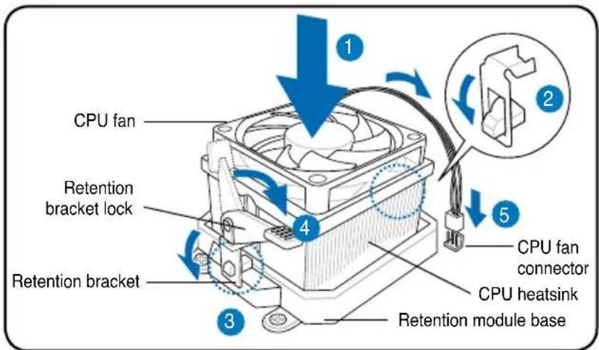
- Place the heatsink on top of the installed CPU.
IMPORTANT. Make sure that the fan and heatsink assembly perfectly fits the retention mechanism module base; otherwise you can not lock the retention bracket.
- Attach one end of the retention bracket to the retention module base.
- Attach the other end of the retention bracket (near the retention bracket lock) to the retention module base until it clicks in place.
NOTE. Your boxed CPU should come with installation instructions for the CPU, fan/heatsink assembly, and the retention mechanism. If the instructions in this section do not match the CPU documentation, follow the latter.
- Push down the retention bracket lock on the retention mechanism to secure the fan and heatsink to the module retention module base.
- Connect the CPU fan cable to the connector on the motherboard.
CAUTION: Do not forget to connect the CPU fan connector! Hardware monitoring error can occur if you fail to plug this connector.
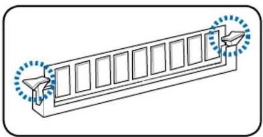
Installing a DIMM
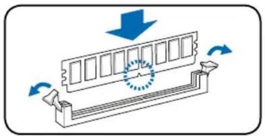
- Locate the DIMM sockets on the motherboard.
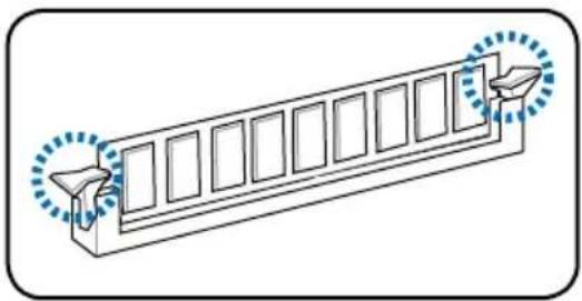
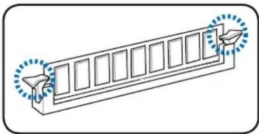
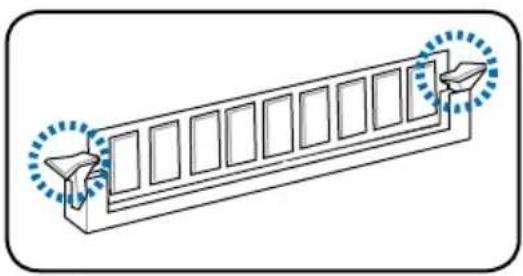
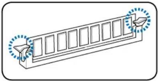
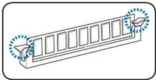
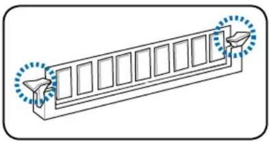
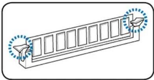
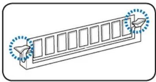
- Unlock a DIMM socket by pressing the retaining clips outward.
- Align a DIMM on the socket such that the notch on the DIMM matches the break on the socket.
- Push the DIMM into the socket until the retaining clips snap inward.
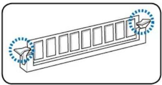
CAUTION:
- Unplug the power supply before adding or removing DIMMs. Failure to do so may cause damage to the motherboard and/or components.
- A DDR DIMM is keyed with a notch so that it fits in only one direction. Do not force a DIMM into a socket to avoid damaging the DIMM.
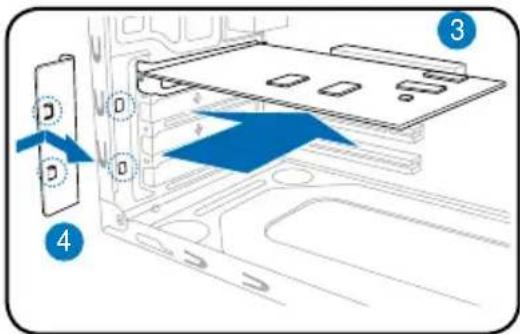
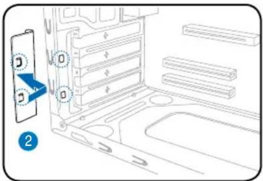
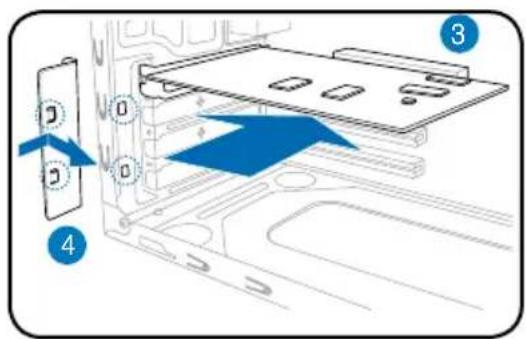
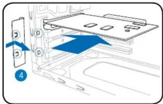
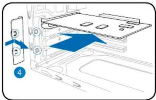
Installing an expansion card
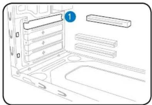
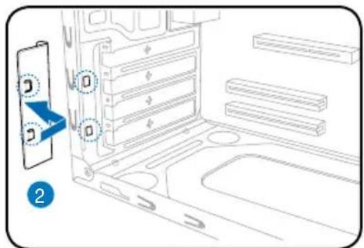
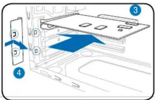
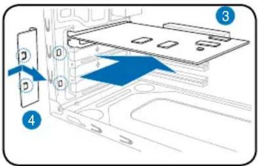
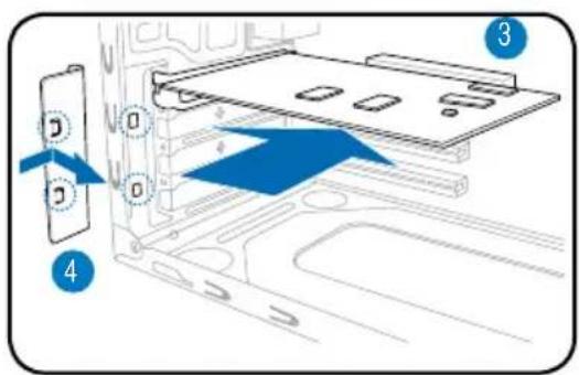
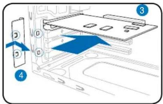
the slot that you intend to use.
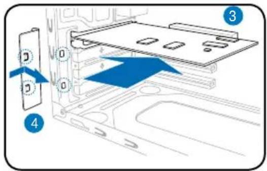
- Insert the card connector into the slot, then press the card firmly until it fits in place.
- Replace the metal bracket lock.
- Remove the metal bracket lock. 1. Remove the metal
Installing storage drives
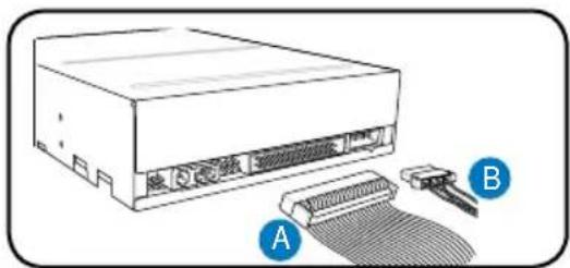
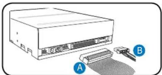
Optical drive
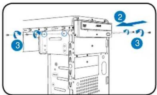
- Place the chassis upright, then remove the upper 5.25" drive bay metal plate cover.
- Insert the optical drive into the bay, then carefully push the drive until its screw holes align with the holes on the bay.
- Secure the optical drive with two screws on both sides of the bay.
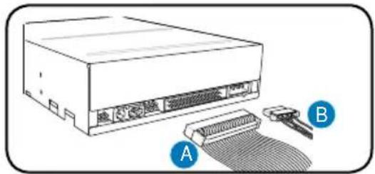
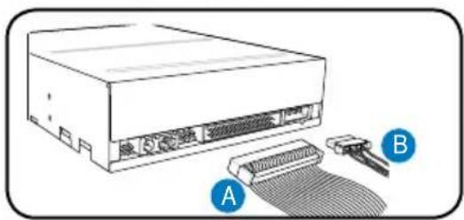
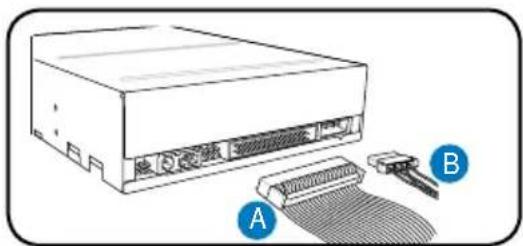
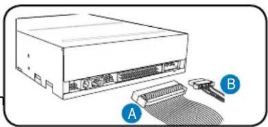
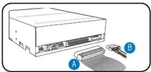
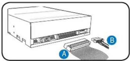
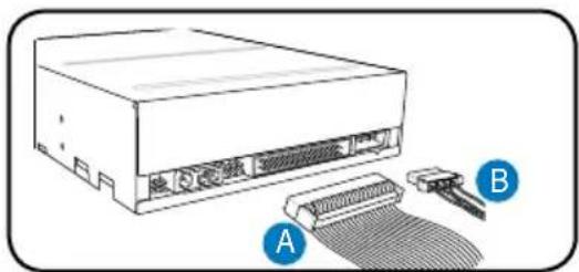
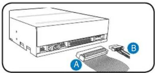
- Connect the IDE (A) and power (B) plugs to connectors at the back of the drive.
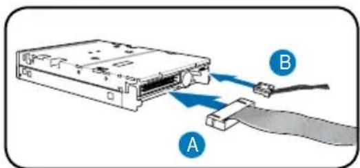
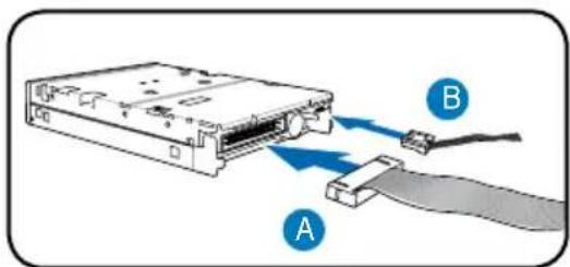
Floppy disk drive
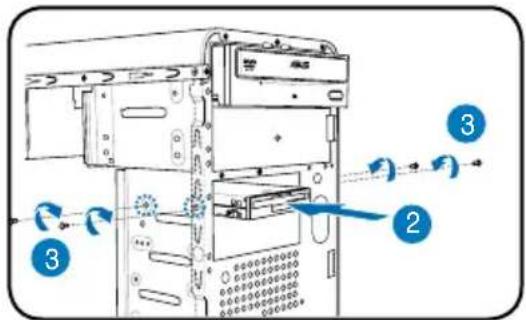
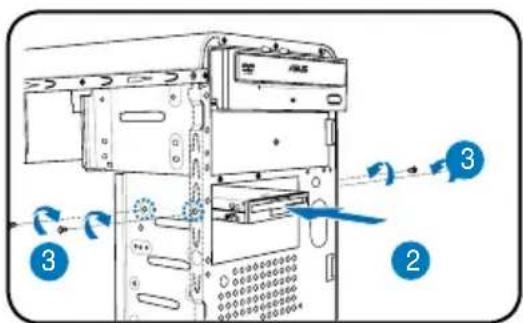
- Place the chassis upright, then remove the lower 3.5" drive bay metal plate cover.
- Insert the floppy disk drive into the bay, then carefully push the drive until its screw holes align with the holes on the bay.
- Secure the floppy disk drive with two screws on both sides of the bay.
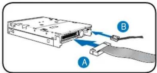
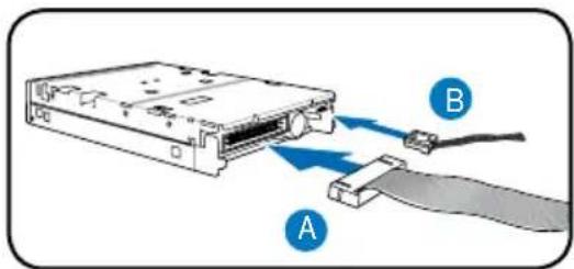
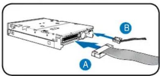
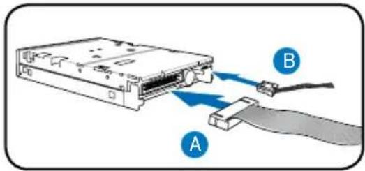
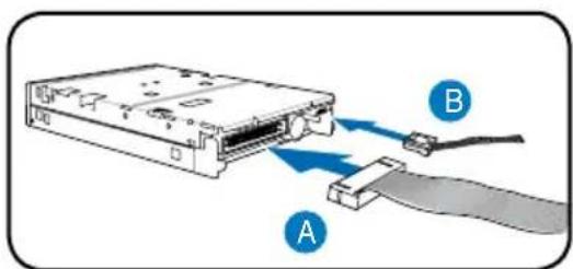
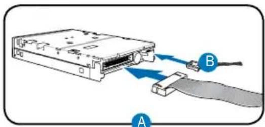
- Connect the signal (A) and power (B) plugs to connectors at the back of the drive.
Hard disk drive
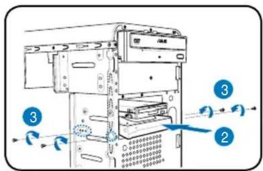
- Place the chassis upright, then remove the upper 3.5" drive bay metal plate cover.
- Insert the hard disk drive into the bay, then carefully push the drive until its screw holes align with the holes on the bay.
- Secure the hard disk drive with two screws on both sides of the bay.
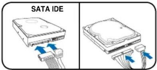
- For SATA HDD: Connect the SATA signal and power plugs to the connectors at the back of the drive.
For IDE HDD: Connect the IDE and power plugs to the connectors at the back of the drive.
Removing the bay covers and reinstalling the front panel assembly and side cover
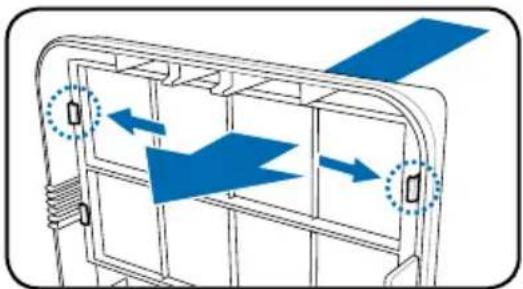
If you installed an optical and/or floppy disk drive, remove the bay cover(s) on the front panel assembly before reinstalling it to the chassis. To do this:
- Locate the bay cover locks.
- Press the locks outward to release the bay cover.
- Push the bay cover inward, then set it aside.
- Follow the same instructions to remove the 3.5" drive bay cover.
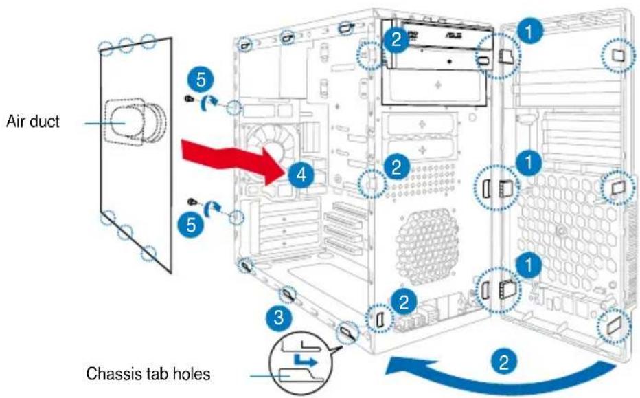
To reinstall the front panel assembly and side cover:
- Insert the front panel assembly hinge-like tabs into the holes on the right side of the chassis.
- Swing the front panel assembly to the left, then insert the hooks into the chassis until the front panel assembly fits in place.
- Insert the six side cover hooks into the chassis tab holes.
- Push the side cover toward the front panel until it fits in place.
- Secure the cover with the two screws you removed earlier.
ASUS
V-Series
WARNING:
ASUS PC (Desktop Barebone)
Installation Manual
Front Panel
WARNING:
Floppy Disk Drive
Hard Disk Drive
ASUS PC (Desktop Barebone)
WARNING:
Floppy Disk Drive
Hard Disk Drive
WARNING:
Floppy disk drive
WARNING:
Disk drive

Hard disk
Front panel features
WARNING.
WARNING.
Floppy disk drive
Hard disk
WARNING.
Front panel features
WARNING!
Hard disk drive
- ASUS PC (DESKTOP BAREBONE)
- INSTALLATION MANUAL
- FRONT PANEL FEATURES
- REAR PANEL FEATURES
- INTERNAL COMPONENTS
- SELECTING THE VOLTAGE
- REMOVING THE SIDE COVER AND FRONT PANEL ASSEMBLY
- INSTALLING A CPU
- INSTALLING AN INTEL® PENTIUM® 4 CPU IN THE LGA775 PACKAGE
- INSTALLING AN AMD CPU
- INSTALLING THE CPU FAN AND HEATSINK ASSEMBLY INSTALLING AN INTEL® PENTIUM® 4 CPU HEATSINK AND FAN
- INSTALLING AN AMD CPU HEATSINK AND FAN
- INSTALLING A DIMM
- CAUTION
- INSTALLING AN EXPANSION CARD
- INSTALLING STORAGE DRIVES
- OPTICAL DRIVE
- FLOPPY DISK DRIVE
- HARD DISK DRIVE
- REMOVING THE BAY COVERS AND REINSTALLING THE FRONT PANEL ASSEMBLY AND SIDE COVER
- ASUS
- V-SERIES
- WARNING
- FRONT PANEL
- DISK DRIVE
- HARD DISK
Brand : ASUS
Model : V2M3A3200
Category : Desktop computer