
MISTY100 - Fan AERIAN - Free user manual and instructions
Find the device manual for free MISTY100 AERIAN in PDF.

| Product Type | Fan with misting function on stand |
| Brand | Aerian |
| Model | MISTY100 |
| Rated Voltage | 220-240 V~ |
| Frequency | 50 Hz |
| Rated Power | 100 W |
| Standby Consumption | 0.22 W |
| Maximum Airflow | 40.58 m³/min |
| Maximum Air Speed | 2.97 m/s |
| Service Value | 0.84 (m³/min)/W |
| Sound Power Level | 60.04 dB(A) |
| Water Tank Capacity | 2 litres maximum |
| Number of Speeds | 3 (fast, medium, slow) |
| Operating Modes | Normal, Breeze, Sleep |
| Timer | Up to 7.5 hours (in 0.5-hour increments) |
| Oscillation | Yes, with dedicated button |
| Misting Function | Yes, with low water level indicator |
| Remote Control | Yes, AAA batteries (not included) |
| Remote Control Range | 3 metres, 60° max angle |
| Cleaning | Damp cloth, do not immerse the motor |
| Safety | Protective grilles, unplug before maintenance |
| After-Sales Service France | Darty: 0 978 970 970 (24/7) |
| After-Sales Service Belgium | Vanden Borre: +32 2 334 00 00 (Mon-Fri 8am-6pm, Sat 9am-6pm) |
Frequently Asked Questions - MISTY100 AERIAN
User questions about MISTY100 AERIAN
0 question about this device. Answer the ones you know or ask your own.
Ask a new question about this device
Download the instructions for your Fan in PDF format for free! Find your manual MISTY100 - AERIAN and take your electronic device back in hand. On this page are published all the documents necessary for the use of your device. MISTY100 by AERIAN.
USER MANUAL MISTY100 AERIAN
natural_image
White outdoor fan with mesh grille and stand, no visible text or symbols
OPERATING INSTRUCTIONS

MANUEL D'UTILISATION

HANDLEIDING

| Language of Introduction | Page |
| English | EN1 - EN7 |
| French | FR8 - FR15 |
| Dutch | NL16 - NL23 |
| Spanish | ES24 - ES30 |
| Portuguese | PT31 - PT37 |
Read the instructions carefully before operating the appliance and keep them for future reference.
WARNINGS
- This appliance is intended for domestic household use only and should not be used for any other purpose or in any other application, such as for non-domestic use or in a commercial environment.
- This appliance can be used by children aged from 8 years and above and persons with reduced physical, sensory or mental capabilities or lack of experience and knowledge if they have been given supervision or instruction concerning use of the appliance in a safe way and understand the hazards involved. Children shall not play with the appliance. Cleaning and user maintenance shall not be made by children without supervision.
- If the supply cord is damaged, it must be replaced by the manufacturer, its service agent or similarly qualified persons in order to avoid a hazard.
- Regarding the method on how to assembly and how to fix the fan with screws, refer to the section "ASSEMBLY".
- Regarding the detailed information of filling,
EN1
cleaning and descaling, refer to the section "Cleaning and maintenance & descaling" on pages EN12 of the manual.
- Unplug the appliance during filling and cleaning.
- Warning! After assembly, it's strictly forbidden to remove the protective guards during maintenance or cleaning. Never use the fan without the guards in place.
- The battery must be removed from the appliance before it is scrapped.
- The battery is to be disposed of safely.
- Different types of batteries or new and used batteries are not to be mixed.
- Batteries of the same or equivalent type as recommended are to be used.
- Batteries are to be inserted with the correct polarity.
- Exhausted batteries are to be removed from the product.
- Attention should be drawn to the environmental EN2 EN3
aspects of battery disposal. Don't throw used batteries in dustbin. Please contact your retailer in order to protect the environment.
- The batteries (batteries installed) shall not be exposed to excessive heat such as sunshine, fire or the like.
IMPORTANT SAFETY INSTRUCTIONS
- To protect against electric shock, do not immerse the fan, cord or plug in water or any other liquid.
- Turn off and unplug the fan from the mains socket when not in use, when moving from one location to another, before assembly and cleaning.
- Do not let the power cord hang over the edge of a bench or table, touch hot surfaces or become knotted.
- Make sure the appliance is placed on a stable surface when used.
- Do not let hair, net curtains, tablecloths or loose clothing come into contact with the moving parts of the fan as it may cause damage or injuries.
- Do not use this fan near a window that may have condensation on it.
- Do not use this fan with any external semi-conductor speed controller.
- Do not use this fan in areas where flammable liquids are used or stored.
• Do not use outdoors. - Never attempt to make any repair to the appliance yourself. Contact a qualified service agent or the store where you purchased the appliance to carry out any repairs or maintenance.
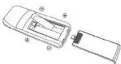
Remote control battery handling and usage:
Only adults should handle the batteries. Do not allow a child to use this remote control unless the battery cover is securely attached to the remote control.
The battery type used in this remote is two AAA size batteries (not included). These batteries are located in the remote control and are readily accessible.
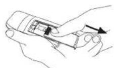
Battery removal
Remove the battery cover on the rear of the remote control and remove the batteries.
These batteries must be disposed of at your local recycling point.
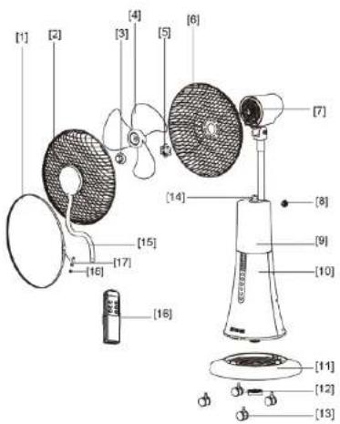
PARTS
EN5
- Fixing strip
- Front guard
- Blade nut
- Fan blade
- Rear guard nut
- Rear guard
- Motor
- Locking nut
- Water tank
- Housing with control panel
- Base
- Base nut
- Castors (4)
- Retainer ring for mist tube
- Misting tube
- Remote control
- Fixing strip screw
- Fixing strip nut
ASSEMBLY
CAUTION:
DO NOT insert the mains plug into the mains socket until the fan has been completely assembled. Never operate the fan with a cracked or damaged fan blade.
Assembling the Base and Fan Body
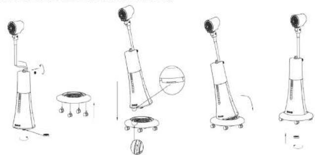
natural_image
Line drawings of five different robotic devices with no visible text or symbolsAssembling the Rear Guard and the Fan Blade
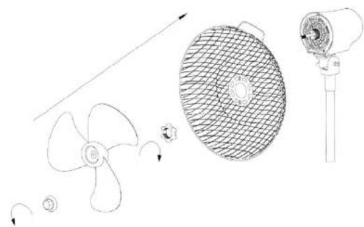
natural_image
Technical line drawing of a propeller, fan blade, and fan assembly (no text or symbols)EN6 EN7
Assembling the Front Guard
Wrap the fixing strip around the rims of the front and rear guards. Fix it to the guards using the screw and nut.
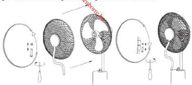
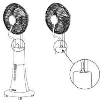
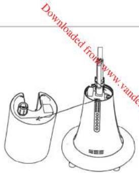
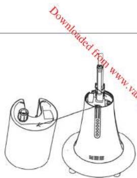
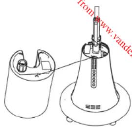
Assembling the Misting Tube
One end of the misting tube has been pre-installed to the misting inlet on the front guard. Connect the other end to the water tank outlet.
CAUTION: Make sure the misting tube is securely in place when the misting function is activated, otherwise the metal components of your fan will easily get rusty.
natural_image
Technical line drawing of a two-tiered outdoor fan with a magnified inset showing internal components (no text or symbols)OPERATION
Place the fan on a stable, level surface. Plug the fan in the mains socket. The indicator light Ⓞ will illuminate.
Indicator lights on the control panel
| 05H | 1H |
| 2H | 4H |
Buttons on the control panel
| Button Function | |
| Press this button to turn on or on the appliance. | |
| Repeatedly press this button to adjust the desired speed:• The indicator light(1) and the corresponding speed indicator light will illuminate.High speedMedium speedLow speed | |
| Repeatedly press this button to set the timer for up to 7.5 hours.The illuminated indicator light(s) indicate the number of hours selected.Each button press will increase the time by 0.5 hour increments.To cancel the timer function, repeatedly press this button until all timer indicator lights go out. | |
| 1. Press this button to activate the misting function.The indicator light(1) will illuminate.2. Press this button again to deactivate this function.The indicator light(1) will go out.Water shortage warning:When the indicator light(1) is flashing and beeps are heard after the misting function is activated, please fill the water tank with sufficient water (refer to the section Filling the Water Tank with Water below).Attach the water tank filled with water back to the fan body and then press this button to use this misting function. | |
| Repeatedly press this button to select the desired operating mode. The corresponding indicator light will illuminate.Normal(1): Repeatedly press to set the desired fan speed and the fan will operate at a set speed.Breeze(1): The fan will operate in natural wind mode by randomly alteranting the fan speed.Sleep(2): The fan will decrease the fan speed step by step. | |
| Press this button to activate the oscillation function. The indicator light(2) will illuminate.To deactivate this function, press this button again. The indicator light(2) will go out. | |
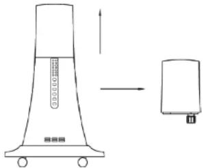
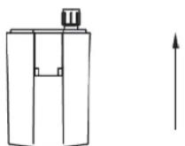
FILLING THE WATER TANK WITH WATER
-
Remove the water tank by lifting it up and then take it out.
-
Turn the water tank upside down.
-
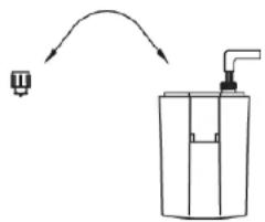
Unscrew the tank cap and fill the tank with max. 2 litres water.
-
Securely fasten the tank cap and attach it back to the fan body.
natural_image
Simple line drawing of a pump bottle with an arrow indicating direction (no text or symbols)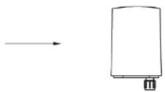
EN10 EN11
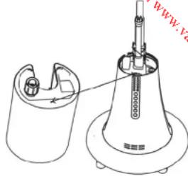
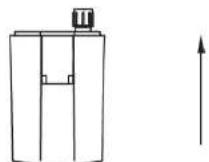
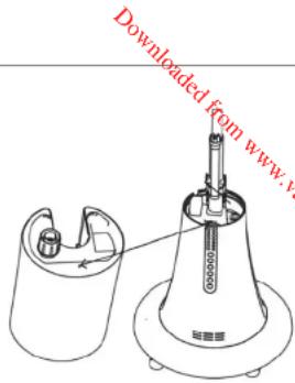
natural_image
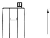
Technical line drawing of a mechanical device with a conical base and internal components (no text or symbols)NOTE: Make sure that the pillar at the bottom of the tank is inserted into the hole of the fan body. When it is inserted, you will hear a slight click.
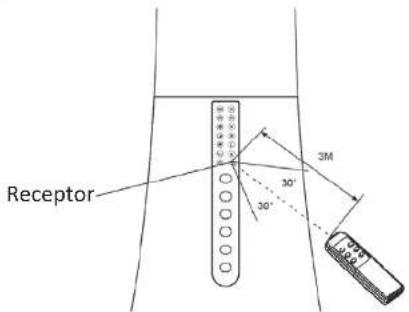
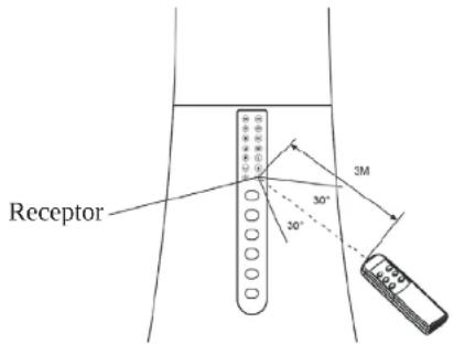
- Point the remote control at the receiver on the front of the fan.
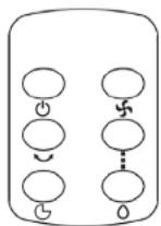
- The buttons on the remote correspond to those on the control panel of the fan body.
- They operate by pressing in the same way described in the previous instructions.
- The distance between the remote and receiver should be no more than 3 metres. The remote control must be pointed towards the receptor within 60 degrees.
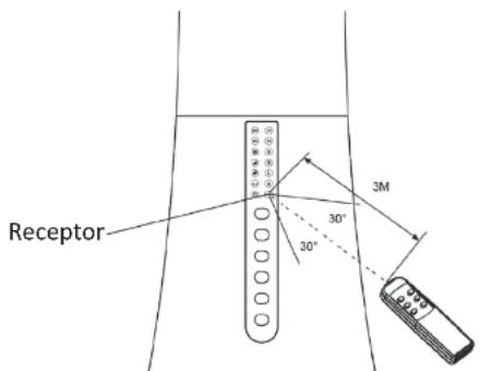
- If the remote control does not operate as expected, replace the batteries.
CLEANING AND MAINTENANCE
Always turn off and unplug the fan from the mains socket before cleaning.
Once the fan guard was assembled, it's forbidden to take off the guards when cleaning.
Clean the fan with a slightly damp cloth, and then dry it.
Do not immerse the motor housing in water or any other liquid.
Do not use chemical or abrasive cleaner.
EN12
SPECIFICATIONS
Ratings: 220-240V\~, 50Hz,100W
| Maximum fan flow rate (F): 40.58 m^3/min | |
| Service value (SV): | 0.84 ( m^3/min )/W |
| Standby power consumption ( P_SB ): | 0.22 W |
| Fan sound power level ( L_WA ): | 60.04 dB(A) |
| Maximum air velocity (c): 2.97 meters/sec | |
| Measurement standard for service value: | COMMISSION REGULATION(EU) No 206/2012 & (EU)2016/2282IEC 60879:1986EN 50564:2011EN 60704-2-7:1998EN 60704-1:2010+A11:2012 |
DISPOSAL

As a responsible retailer we care about the environment. As such we urge you to follow the correct disposal procedure for the appliance and packaging materials. This will help conserve natural resources and ensure that it is recycled in a manner that protects health and the environment.
You must dispose of this appliance and its packaging according to local laws and regulations.
Because this appliance contains electronic components, the appliance and its accessories must be disposed of separately from household waste when the appliance reaches its end of life.
Contact your local authority to learn about disposal and recycling.
EN13
The appliance should be taken to your local collection point for recycling. Some collection points accept appliance free of charge.
We apologise for any inconvenience caused by minor inconsistencies in these instructions, which may occur as a result of product improvement and development.
Darty Holdings SAS © 14 route d'Aulnay 93140 Bondy, France 27 / 11 / 2017
EN14
natural_image
Line drawings of four different types of medical or robotic devices with no visible text or symbolsnatural_image
Technical line drawing of a propeller and fan assembly (no text or symbols)FR20 FR21
natural_image
Technical line drawing of a two-tiered outdoor fan with a base, showing internal components and a close-up inset (no text or symbols)FONCTIONNEMENT
natural_image
Technical line drawing of a device with three views: top, side, and front (no text or symbols)flowchart
graph LR
    A["Container with inlet"] --> B["Piping Bag with outlet"]
    B --> C["Storage Unit with inlet"]
FR24 FR25
Hotline Darty France
natural_image
Line drawings of five different medical or robotic devices with no visible text or symbolsnatural_image
Line drawings of various household appliances including a fan, fan blade, and fan with blades (no text or symbols)NL34 NL35
De nevelbuis bevestigen
natural_image
Technical line drawing of a two-tiered outdoor fan with a close-up inset showing internal components (no text or symbols)WERKING
HET WATERRESERVOIR MET WATER VULLEN
natural_image
Simple line drawing of a container with a valve and a small object, no text or symbols present.
NL38 NL39
flowchart
graph TD
    A[" "] --> B[" "]
    B --> C[" "]
    C --> D[" "]
    D --> E[" "]
    E --> F[" "]
    style A fill:#fff,stroke:#000
    style B fill:#fff,stroke:#000
    style C fill:#fff,stroke:#000
    style D fill:#fff,stroke:#000
    style E fill:#fff,stroke:#000
natural_image
Line drawings of four different robotic devices with no visible text or symbolsnatural_image
Technical line drawing of a propeller, fan blade, mesh fan, and cylindrical device (no text or symbols)ES48 ES49
natural_image
Technical line drawing of a two-tiered outdoor fan with a close-up inset showing internal components (no text or symbols)MODO DE EMPLEO
natural_image
Simple line drawing of a funnel-shaped device with an arrow pointing to a rectangular component (no text or symbols)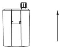
natural_image
Simple line drawing of a pump bottle with an arrow indicating direction (no text or symbols)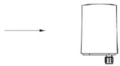
ES52 ES53
natural_image
Line drawings of four different types of industrial robotic devices with no visible text or symbolsnatural_image
Line drawings of propeller components including fan, mesh cover, and fan assembly (no text or labels)PT62 PT63
natural_image
Technical line drawing of a two-tiered outdoor fan with a close-up inset showing internal components (no text or symbols)FUNCIONAMENTO
natural_image
Simple line drawing of a pump bottle with an arrow indicating direction (no text or symbols)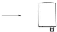
PT66 PT67
flowchart
graph TD
    A[" "] --> B[" "]
    B --> C[" "]
    C --> D[" "]
    D --> E[" "]
    E --> F[" "]
    F --> G[" "]
    style A fill:#fff,stroke:#000
    style G fill:#fff,stroke:#000
Downloaded from www.vandenborie.be
- Read the instructions carefully before operating the appliance and keep them for future reference.
- WARNINGS
- IMPORTANT SAFETY INSTRUCTIONS
- Remote control battery handling and usage:
- Battery removal
- ASSEMBLY
- CAUTION:
- Assembling the Front Guard
- Assembling the Misting Tube
- OPERATION
- FILLING THE WATER TANK WITH WATER
- CLEANING AND MAINTENANCE
- SPECIFICATIONS
- DISPOSAL
- FONCTIONNEMENT
- Hotline Darty France
- De nevelbuis bevestigen
- WERKING
- HET WATERRESERVOIR MET WATER VULLEN
- MODO DE EMPLEO
- FUNCIONAMENTO
Brand : AERIAN
Model : MISTY100
Category : Fan