
522301005 - Battery charger Absina - Free user manual and instructions
Find the device manual for free 522301005 Absina in PDF.
| Brand | Absina |
| Model | 522301005 |
| Product type | EV charging cable mode 2 |
| Input voltage | 400 V three-phase |
| Adjustable charging current | 8 A, 10 A, 13 A, 16 A |
| Max rated power | 11 kW |
| Vehicle plug type | IEC 62196-2 Type 2 |
| Cable length | 5+1 m |
| Weight | 2 800 g |
| Control box dimensions | 240 x 107 x 61 mm |
| Protection rating (vehicle plug) | IP55 (when coupled) |
| Protection rating (control box) | IP54 |
| Operating temperature | -20 °C to +50 °C |
| Number of phases | 3 phases |
| Differential protection (RCD) | 30 mA AC + 6 mA DC |
| Protection functions | Overvoltage, undervoltage, overload, overtemperature, residual current, PE monitoring |
| Connection cycles | ≥ 10 000 (without load) |
| Flammability class | UL94 V-0 |
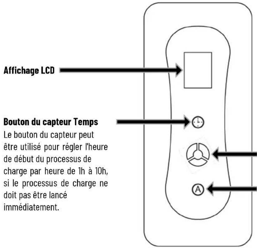
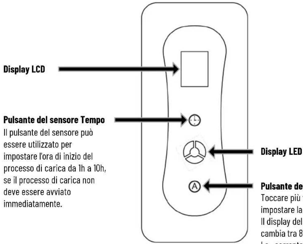
| Display | LCD with LED indicators (green, blue, red) |
| Additional features | Charging timer (1-10 h), charging current adjustment |
| Maintenance and cleaning | Clean with a dry cloth only, no water or aggressive products |
| Warranty | 2 years |
Frequently Asked Questions - 522301005 Absina
User questions about 522301005 Absina
0 question about this device. Answer the ones you know or ask your own.
Ask a new question about this device
Download the instructions for your Battery charger in PDF format for free! Find your manual 522301005 - Absina and take your electronic device back in hand. On this page are published all the documents necessary for the use of your device. 522301005 by Absina.
USER MANUAL 522301005 Absina
flowchart
graph LR
    A["Plug-in"] --> B["Cable Insert"]
    B --> C["Switch Insert"]
    C --> D["Buscan Cable Insert"]
    D --> E["Buscan Cable Pull-up"]
    E --> F["Plug-in with Battery"]
Ladevorgang beenden
flowchart
graph LR
    A["Plug"] --> B["Hand Tool"]
    B --> C["Plug Outlet"]
BEDIENELEMENTE
Thank you for purchasing your new ABSINA EV charging cable mode 2. With the help of the operating instructions, you will be able to use the functions of your charging cable optimally. We hope you enjoy using your new charging cable.
Your ABSINA team.
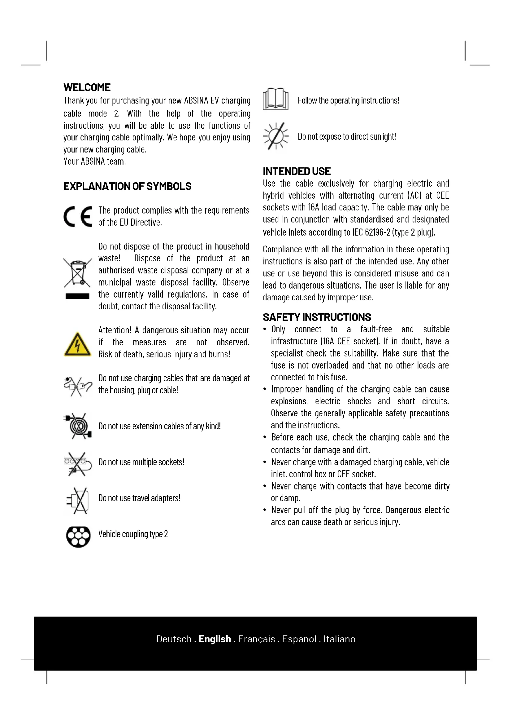
EXPLANATION OF SYMBOLS

The product complies with the requirements of the EU Directive.

Do not dispose of the product in household waste! Dispose of the product at an authorised waste disposal company or at a municipal waste disposal facility. Observe the currently valid regulations. In case of doubt, contact the disposal facility.

Attention! A dangerous situation may occur if the measures are not observed. Risk of death, serious injury and burns!

Do not use charging cables that are damaged at the housing, plug or cable!

Do not use extension cables of any kind!

Do not use multiple sockets!

Do not use travel adapters!

Vehicle coupling type 2

Follow the operating instructions!

Do not expose to direct sunlight!
INTENDED USE
Use the cable exclusively for charging electric and hybrid vehicles with alternating current (AC) at CEE sockets with 16A load capacity. The cable may only be used in conjunction with standardised and designated vehicle inlets according to IEC 62196-2 (type 2 plug).
Compliance with all the information in these operating instructions is also part of the intended use. Any other use or use beyond this is considered misuse and can lead to dangerous situations. The user is liable for any damage caused by improper use.
SAFETY INSTRUCTIONS
- Only connect to a fault-free and suitable infrastructure (16A CEE socket). If in doubt, have a specialist check the suitability. Make sure that the fuse is not overloaded and that no other loads are connected to this fuse.
- Improper handling of the charging cable can cause explosions, electric shocks and short circuits. Observe the generally applicable safety precautions and the instructions.
- Before each use, check the charging cable and the contacts for damage and dirt.
- Never charge with a damaged charging cable, vehicle inlet, control box or CEE socket.
- Never charge with contacts that have become dirty or damp.
-
Never pull off the plug by force. Dangerous electric arcs can cause death or serious injury.
-
Only connect the charging cable to vehicle inlets and CEE sockets that are protected from water, direct sunlight, moisture and other liquids.
- Some electric vehicles allow the vehicle to be started with the charging cable plugged in. Always make sure to disconnect the charging cable before driving off.
- Do not use the charging cable with an extension cable or an adapter. Modifications or alterations are dangerous to life and will immediately void the warranty.
- If the plug connection smokes or melts, never touch the charging cable. If possible, stop the charging process. Disconnect the relevant mains socket from the power supply (fuse, FI, switch).
- Make sure that the charging cable is not accessible to children. Only persons with a valid driving licence for motor vehicles may operate the charging cable.
- Only use the cable in protected outdoor areas.
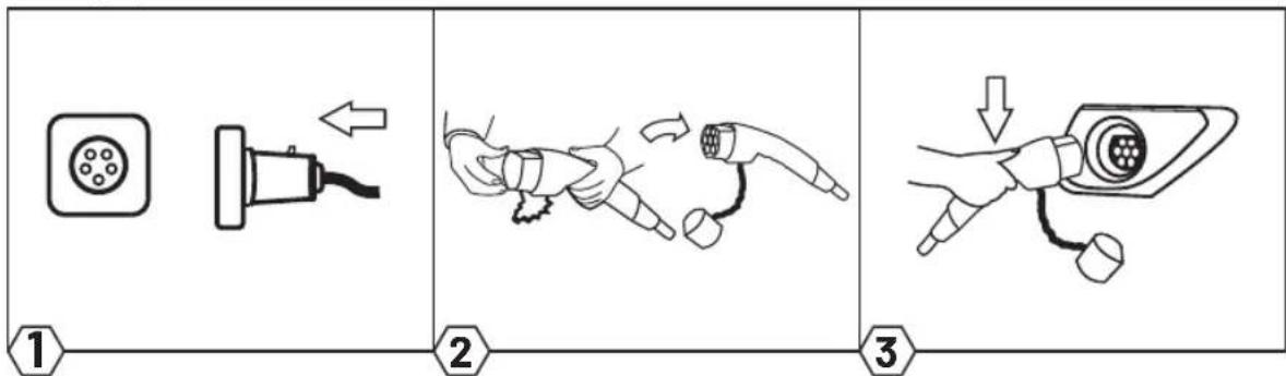
OPERATION
- Read the instructions for the charging cable and the vehicle completely and carefully.
- Switch off the vehicle engine and put the gear lever in park.
- Connect the mains plug of the charging cable to a suitable socket (400V 16A).
- The green LED lights up to indicate that the vehicle is ready for charging.
- Remove the protective cap from the charging plug and connect the plug to the vehicle's charging socket.
- The charging process starts automatically as soon as the blue LED starts flashing.
- Charging is complete when the green LED and the blue LED light up continuously.
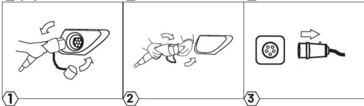
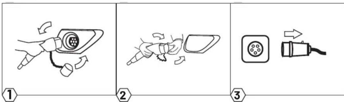
- When the charging process is finished, pull the charging plug out of the charging socket of the vehicle and then pull the mains plug out of the mains socket (vehicle must be unlocked).
- Put the protective cap on the charging plug and roll up the cable without kinks.
Start charging
flowchart
graph LR
    A["Plug-in"] --> B["Cable Insert"]
    B --> C["Buson Cable Insert"]
    C --> D["Buson Cable Pull-up"]
    D --> E["Buson Cable Pull-up"]
End charging

flowchart
graph LR
    A["1: Battery charging"] --> B["2: Plug charging"]
    B --> C["3: Plug charging with arrow"]
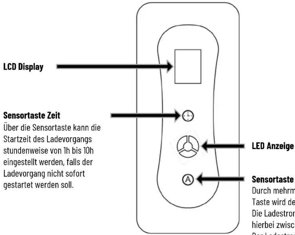
OPERATING ELEMENTS

LED display
Sensor button A
Touch the button several times to set the charging current.
The charging current display changes between 8A-10A-13A-16A.
The charging current cannot be changed during the charging process.
LCD CHARGING STATUS INDICATOR

ERROR
The charging cable has several monitoring functions that are indicated by the LEDs.
| LED GREEN | LED BLUE | LED RED | DESCRIPTION DECLARATION |
| ● | ○ | ○ | Standby Sleep mode. |
 | ○ | ○ | Normal connection |
| ● |  | ○ | Charging |
| ● | [S7Z2] | ○ | Charging completed |
| ○ | [YXXX][KXHZ] | ● | Failed self-test |
| ○ | [W8HS] | 2x [65xC] | Low voltage |
| ○ |  | 3x  | Over voltage |
| ○ | [OKBA] | 4x  | Leakage current |
| ○ |  | 5x [TSTD] | Over current |
| ○ | [HD40] | 6x  | Charger overheated |
| ○ |  | 7x  | PE error |
 = ON = FLASH= OFF = ON = FLASH= OFF  | |||
TECHNICAL DATA
| Input: | 400V |
| Charging plug: | IEC62196-2 Type 2 |
| RCD: | 30mA AC + 6mA DC |
| Rated power: | max. 11 kW |
| Output: | 8A - 10A - 13A - 16A |
| Number of phases: | 3-phase |
| Contact resistance: | ≤0.3mΩ(L/N) |
| Isolation resistance: | 500MΩ(1.000V AC) |
| High voltage strength | 2.600V AC |
| Contact temperature rise: | ≤50K |
| Charging mode: | IEC 61851-1 |
| Operating humidity: | 5% -95% non condensing |
| Protectionclass: | IP55 (Vehicle plug in mated condition)IP54 (Control box) |
| Flammability class: | UL94 V-0 |
| Protective functions: | Overvoltage, undervoltage, overcharging and overheating protection (charge at +85°C interrupt, continue at 55°C), residual current, PE control |
| Pull-off force: | 45N...80N |
| Plugging cycles: | ≥10.000x (Load-free) |
| Dimensions control box: | 240x107x61mm |
| Operating temperature: | -20°C...+50°C |
| Cable | 5+1m length, 3*2.5mm2+0.75mm2 |
| Weight | 2.800g |
LOADING TIME
The duration of the charging process depends on the capacity, the state of charge of the vehicle's high-voltage battery and the permissible charging power of the charging cable and the CEE socket. The charging current (max. 16A) is regulated by the vehicle (charging power may vary). At very low and very high temperatures, the charging performance may be impaired.
CLEANING AND STORAGE
Only clean the cable when it is not connected to the vehicle and not to the socket. Only clean the charging cable and the dirty contacts with a dry cloth. Never use harsh cleaning agents, water or steam cleaners. Never immerse the product in liquids. Store the charging cable with the protective caps on in a dry and clean place.
ENVIRONMENTAL PROTECTION
Information according to the Electrical and Electronic Equipment Act (ElektroG):
Since 24 March 2006, old electrical appliances may not be disposed of with household waste. These electrical and electronic appliances are marked with a crossed-out dustbin. Owners of old appliances from private households can dispose of them at the collection points of the public waste management authorities or at the take-back points set up by manufacturers or distributors in accordance with the ElektroG.
GUARANTEE
The product is guaranteed for 2 years. No guarantee can be given for damage resulting from non-observance of the operating instructions.
BIENVENUE
flowchart
graph LR
    A["1: Plug-in plug"] --> B["2: Cable insertion"]
    B --> C["3: Charging plug with battery"]
Fin de la charge
flowchart
graph LR
    A["1: Battery charging"] --> B["2: Plug charging"]
    B --> C["3: Plug charging with arrow"]
ÉLÉMENTS DE TRAVAIL
flowchart
graph LR
    A["Plug-in"] --> B["Cable Insert"]
    B --> C["Buson Cable Insert"]
    C --> D["Buson Cable Pull-up"]
    D --> E["Buson Cable Pull-up"]
Terminar de cargar

flowchart
graph LR
    A["1: Battery charging"] --> B["2: Plug charging"]
    B --> C["3: Plug charging with arrow"]
flowchart
graph LR
    A["1: Battery charging"] --> B["2: Plug charging"]
    B --> C["3: Plug charging"]
ELEMENTI OPERATIVI


[Non-Text]
[Non-Text]
[Non-Text]
The results of the present study are presented in Table 1. The mean values of the three parameters were 2.0% (range, 1.5 - 3.0% ) and 2.4% (range, 1.5 - 3.0% ). The mean values of the other parameters were 1.8% (range, 1.5 - 2.5% ) and 1.9% (range, 1.5 - 2.5% ). The mean values of the other parameters were 1.7% (range, 1.5 - 2.5% ) and 1.6% (range, 1.5 - 2.5% ).
DATI TECNICI
DECLARATION OF CONFORMITY

Wir HGPower GmbH
We Kurpfalzstr. 28
97944 Boxberg - Germany
Herewith we declare, that our product
to which this declaration relates, is in conformity to the following standard(s):
IEC 62196-2 : 2017
IEC 61851-1 : 2010
following the provisions of the Directive(s)
(EMV) 2014 / 30 / EU
(LVD) 2014 / 35 / EU
(RoHS) 2011 / 65 / EU
Boxberg, 04. April 2022

https://www.absina.com/pages/faq
... or contact our technical support team
TECHNICAL SUPPORT
HGPOWER GmbH
Kurpfalzstr. 28
97944 Boxberg
Germany
Hotline: +49 7930 9936 220

- Ladevorgang beenden
- EXPLANATION OF SYMBOLS
- INTENDED USE
- SAFETY INSTRUCTIONS
- OPERATION
- Start charging
- End charging
- LED display
- Sensor button A
- ERROR
- LOADING TIME
- CLEANING AND STORAGE
- ENVIRONMENTAL PROTECTION
- GUARANTEE
- BIENVENUE
- Fin de la charge
- Terminar de cargar
- DECLARATION OF CONFORMITY
- TECHNICAL SUPPORT
Brand : Absina
Model : 522301005
Category : Battery charger