TG612BS1 - Hob BRANDT - Free user manual and instructions
Find the device manual for free TG612BS1 BRANDT in PDF.

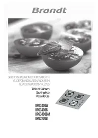
| Product type | Mixed gas/electric hob |
| Number of cooking zones | 3 gas burners + 1 electric plate |
| Surface material | Enameled steel / Vitroceramic (electric plate) |
| Dimensions (W x D x H) | Approx 590 x 520 x 50 mm |
| Net weight | Approx 10 kg |
| Gas supply | Natural gas or butane/propane (injectors supplied) |
| Electrical supply | 230 V ~ 50 Hz |
| Total gas power | 7.75 kW (1.50 + 0.85 + 2.30 + 3.10 kW) |
| Electric plate power | 1.5 kW (diameter 145 mm) |
| Ignition | Integrated electric ignition (button) |
| Safety | Flame safety device (thermocouple) on gas burners |
| Controls | 4 rotary knobs |
| Pan support grates | Removable cast iron grates |
| Cleaning | Clean with a soft cloth and non-abrasive cleaner |
| Spare parts | Grates, injectors, knobs, thermocouples (available via BRANDT after-sales service) |
| Repairability | Repairability index to check on BRANDT website |
| Brand | BRANDT |
| Model | TG612BS1 |
| Manual available | Free user manual in PDF |
Frequently Asked Questions - TG612BS1 BRANDT
User questions about TG612BS1 BRANDT
0 question about this device. Answer the ones you know or ask your own.
Ask a new question about this device
Download the instructions for your Hob in PDF format for free! Find your manual TG612BS1 - BRANDT and take your electronic device back in hand. On this page are published all the documents necessary for the use of your device. TG612BS1 by BRANDT.
USER MANUAL TG612BS1 BRANDT
You have just acquired a BRANDT hob and we would like to thank you.
We have invested all our dedication and know-how in this appliance so that it would best meet your needs. With innovation and performance, we designed it to be always easy to use.
In the BRANDT product range, you will also find a wide choice of ovens, microwaves, ventilation hoods, cookers, dishwashers, washing machines, , fridges and freezers, that you can coordinate with your new BRANDT hob.
Visit our website www.brandt.com where you will find all of our products, as well as useful and complementary information
BRANDT
www.brandt.com
As part of our commitment to constantly improving our products, we reserve the right to make changes to them based on technical advances to their technical and functional features and appearance.

Important :
Before installing and using your appliance, please carefully read this Guide to Installation and Use, which will allow you to quickly familiarise yourself with its operation.
TABLE OF CONTENTS
EN
- Safety recommendations 41
- Environmental protection 42
Description of your appliance 43
1 / INSTALLING YOUR APPLIANCE
- Proper positioning 44
- Flush mounting 44
- Tips for flush mounting 45
- Electrical connection 45
Gas connection 46 - Changing the gas supply 48
2 / USING YOUR APPLIANCE
Description of the top 52
- Switching on gas burners 53
Cookware to be used with gas burners 54
Cookware for electric plate 18
- Switching on the electric plate 18
3 / DAILY CARE OF YOUR APPLIANCE
- Maintaining your appliance 55
4 / SPECIAL MESSAGES, DIFFICULTIES
During operation 56
5 / COOKING CHART
Gas cooking guide 56
Electric cooking guide 21
6/ AFTER-SALES SERVICE 76
- Repairs 24
- Customer relations 24
SAFETY RECOMMENDATIONS
SAFETY RECOMMENDATIONS
- We have designed this cooking hob for use by private persons in their homes.
- This appliance must be installed in compliance with currently applicable regulations and used only in a well-ventilated location. Consult this guide before installing and using your appliance.
- All cooking should take place under your surveillance.
- These cooking hobs are meant to be used exclusively for cooking beverages and foodstuffs and do not contain any asbestos-based materials.
- This appliance is not connected to a combustion by-product disposal system. It must be installed and connected in compliance with all applicable laws. Special attention should be given to applicable regulations concerning ventilation.
- Do not store CLEANING products or FLAMMABLE products (aerosol cans or containers under pressure, as well as papers, cookbooks, etc.) in the cabinet underneath your cooking hob.
- If you use a drawer located under the hob, we recommend that you avoid storing in it items that are heat sensitive (plastic, papers, aerosol cans, etc.).
- Your hob should be disconnected from power and fuel supplies (electricity and gas) before any repairs.
- When you connect the power cables of any electrical appliances plugged in close to the hob, ensure that they are not in contact with the cooking zones.
- As a safety measure, do not forget to close the general supply tap for gas distributed by pipe or the tap of the tank for butane or propane gas after use.
- The CE compliance designation is affixed to these hobs.
- Installation should only be performed by installers and qualified technicians.
-
Before installation, ensure that the conditions of local distribution (gas type and pressure) and the settings of the appliance are compatible.
-
This hob is compliant with standard EN 60335-2-6 relating to the heating of cabinets and the Class 3 standard with regard to installation (as per standard EN 30-1-1).

Warning
The required settings for the hob are written on a sticker located in the plastic bag, as well as on the packaging.
In order to easily locate the reference information for your appliance, we recommend that you note them on the "After-Sales Service Department and Customer Relations" page (this page also explains to you where to find this information on your appliance).
In the event that a crack becomes visible in the glass worktop, immediately unplug the appliance and contact the After-Sales Service department.
ENVIRONMENTAL PROTECTION
EN
ENVIRONMENTAL PROTECTION
- This appliance's packaging material is recyclable. Help recycle it and protect the environment by dropping it off in the municipal receptacles provided for this purpose.
- Your appliance also contains a great amount of recyclable material. It is marked with this label to indicate the used appliances that should not be mixed with other waste. This way, the appliance recycling organised
by your manufacturer will be done under the best possible conditions, in compliance with European Directive 2002/96/EC on Waste Electrical and Electronic Equipment. Contact your town hall or your retailer for the used appliance collection points closest to your home.
- We thank you doing your part to protect the environment.
DESCRIPTION OF YOUR APPLIANCE
- DESCRIPTION OF YOUR HOB
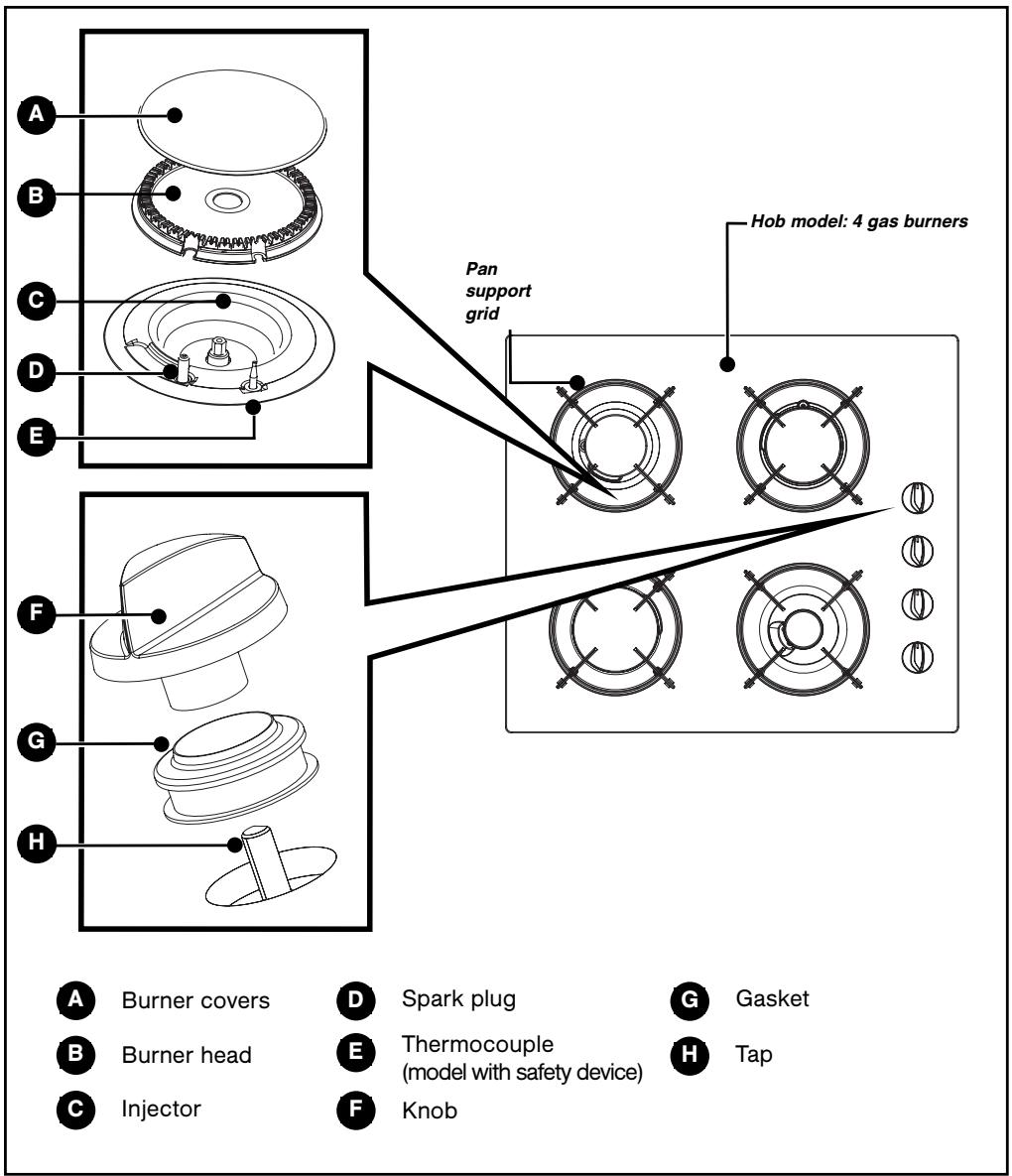

Tip
This Guide to Installation and Use is valid for several models. Minor differences in Is and fittings may emerge between your appliance and the descriptions provided.
1 / INSTALLING YOUR APPLIANCE
EN
| APPLIANCE | ||||
| Width | Depth | Thickness | Model | |
| Cut cabinet standard | 56 cm | 49cm | According to cabinet | 60 cm |
| Cut cabinet standard | 26,5 cm | 49cm | According to cabinet | 30 cm |
| Dimensions total above the work top | 71 cm | 52,2cm | 5 cm | 60 cm |
| 31 cm | 51cm | 5 cm | 30 cm | |
| Dimensions total below the work top | 55,4 cm | 47cm | 5,1 cm | 60 cm |
| 26 cm | 47cm | 5,1 cm | 30 cm | |
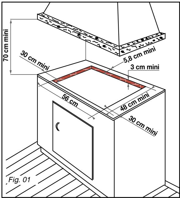
PROPER POSITIONING
Your appliance should be built in the surface of a support cabinet that is a minimum of three cm thick, made of a material that resists heat or that is covered with such a material. So as not to disturb movement of cooking utensils, there should not be to the right or left or back any obstacle within 30 cm of the hob.
if a horizontal divider wall is positioned under the hob, it should be placed between 10 cm and 15 cm away from the top of the work top. In any event, do not store aerosol cans or containers under pressure in any compartment that may exist under the hob (See "Safety Recommendations" chapter).
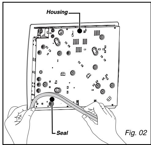
- FLUSH MOUNTING
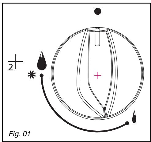
To ensure that the hob and the work top are leaktight, glue the seal provided in the front pocket before installing the hob:
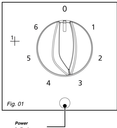
Follow the diagram (Fig. 01).
-
Remove the pan supports, the burner covers and burner heads, noting their positions.
-
Turn the hob over and carefully place it on top of the opening in the cabinet so asnot to damage the knobs and spark plugs.
-
To ensure a tight seal between the housing and the work top, glue the foam seal along the exterior edge of the housing (Fig. 02).
1 / INSTALLING YOUR APPLIANCE
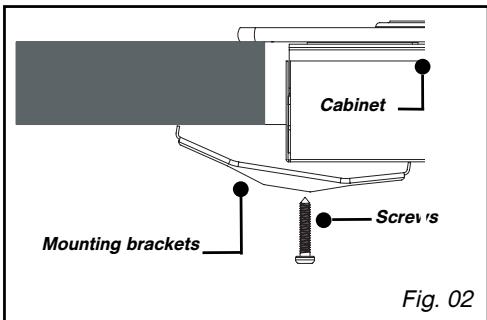
TIPS FOR FLUSH MOUNTING


Mounting brackets
-
Place your hob in the opening of the support cabinet, carefully pulling the table toward you.
-
Reposition the burner heads, burner covers and pan supports on the hob.
Connect your hob to the gas supply (See "Gas Connection" chapter) and to the power supply (See "Electrical Connection" chapter).
-
If you wish, you can immobilise the hob using the four mounting brackets delivered with a screw (Fig. 02) to attach them to the four corners of the housing. You must use the holes provided for this purpose, according to the diagram above (Fig. 01).
-
Stop screwing when the mounting bracket starts to become deformed.
Do not use a screwdriver.
ELECTRICAL CONNECTION
Your hob must be connected to the 220-240 V~ monophase grid via a 2-pole electrical outlet plug + standardised CEI 60083 ground or an all-pole cut-off device, in compliance with the current regulations.
The plug of the electrical outlet must be accessible after installation.
| CABLE CROSS-SECTION TO BE USED | |
| 220-240 V~ - 50 Hz | |
| H05V2V2F -T90 cable Ref. After-sales service: 77x9060 | 3 conductors including one ground wire |
| Cross-section of conductors in mm² | 1 |
| Fuse | 10 A |

Warning
The safety wire (green/yellow) is
connected to the appliance's ground terminal and must be linked to the installation's ground terminal . The fuse in your set-up must be 10 amperes. If the power cable is damaged, it must be replaced by a cable or a special kit available from the manufacturer or its After-Sales Service Department.

Tip
Using a gas cooking appliance results in the generation of heat and humidity in the location where it is installed. Make sure that your kitchen is well-ventilated: keep natural ventilation orifices in your home open or install a mechanical ventilation device (mechanical ventilation hood). - Intensive, prolonged use of the appliance may require additional ventilation; for example, by opening a window or more effective ventilation; by increasing power to the mechanical ventilation, if you have it. (A minimum air flow of 2m^3/h per kW of gas power is required).
Example: 60 cm, 4 gas burners
Total power: 0,85 + 1,5 + 2,3 + 3,1 = 7,75 kW
7,75 kW x 2 = 15,5 m³/H of
minimum flow.
1 / INSTALLING YOUR APPLIANCE
EN
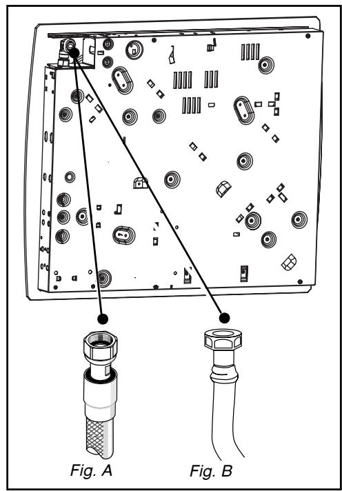
- GAS CONNECTION
- Preliminary comments
If your hob is installed above an oven or if proximity to other heating elements poses a threat of overheating the connection, you must insulate the cable in a rigid pipe.
If a hose or soft pipe (in the case of butane gas) is used, it should not come into contact with a moving part of the cabinet, nor should it pass through a location that may become blocked.
The gas connection must be installed in compliance with applicable regulations in the country of installation.
Gas distributed via natural gas pipes
For your safety, you must choose from the three following connection options:
-
Connection with a rigid pipe made from copper and with screw-on mechanical connectors (G1/2 gas standard mark). Make the connection directly to the end of the elbow fitted on the appliance.
-
Connection with a wavy metal hose (stainless steel) with screw-on mechanical connectors whose service life is unlimited (Fig. A).
-
Connection with a reinforced flexible rubber hose with screw-on mechanical connectors whose service life is 10 years (Fig. B).
Warning
When connecting your hob's gas supply, if you have to change the direction of the elbow fitted on the appliance:
① Change the gasket.
② Screw on the elbow's nut, careful not to exceed a torque of 17 N.m.
1 / INSTALLING YOUR APPLIANCE
Gas supplied by tank or cylinder (butane/propane)
For your safety, you must choose from the three following connection options:
-
Connection with a rigid pipe made from copper and with screw-on mechanical connectors (G1/2 gas standard mark). Make the connection directly to the end of the elbow fitted on the appliance.
-
Connection with a wavy metal hose (stainless steel) with screw-on mechanical connectors whose service life is unlimited (Fig. 01).
-
Connection with a reinforced flexible rubber hose with screw-on mechanical connectors whose service life is 10 years (Fig. 02).
In an existing system, a soft pipe fitted with clamps whose service life is five years may be used. It is necessary in this case to use an adaptor without forgetting to fit a sealing washer between the adaptor and the hob's elbow. (Fig. 03).

You can obtain the adaptor and the sealing
washer from your After-Sales Service
Department.

Screw on the adaptor with a torque
not exceeding 25 N.m.
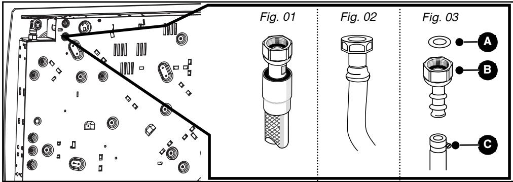
A Sealing washer (not provided)
Adaptor (not supplied)
Clamp (not provided)

All soft pipes and hoses whose
service life is limited must have a maximum
length of two meters and must be
accessible along their entire length. They
must be replaced before the end of their service life (indicated on the pipe).
Regardless of the means of connection chosen, ensure that the connection is air tight, after installation, with soapy water.
1 / INSTALLING YOUR APPLIANCE
EN
CHANGING THE GAS SUPPLY
Warning
Your appliance is sold pre-set for natural gas.
The injectors required for adaption to butane/propane can be found in the plastic bag containing this guide.
Each time you change the gas supply, you must complete the following:
- Adapt the gas connection
- Change the injectors
-
Adjust the hob connections.
-
Adapt the gas connection: Refer to the "Gas Connection" section.
-
Change the injectors, proceeding as follows:
- Remove the pan supports, heads and covers from all burners.
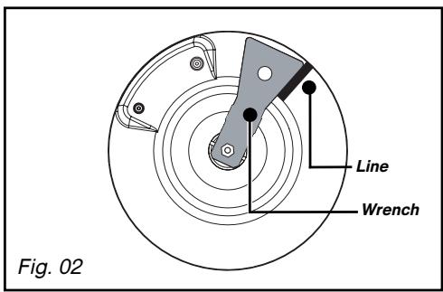
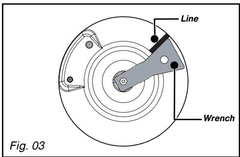
-Using the wrench provided, unscrew the injectors located under each crucible and remove them (Fig. 01).
-- replace with the corresponding gas injectors, in compliance with the positioning of the injectors and the table of gas properties at the end of this section ; to do so:
-First screw them in manually until the injector locks into place. - Apply the wrench to the injector as far as it will go.
- Draw a line on the burner plate using a pencil at the place indicated (Fig. 02).
Turn the wrench clockwise until the line appears on the other side(Fig. 03).

Tip
Each time you change the gas supply, tick the box corresponding to the new gas level on the label found in the plastic bag. Refer to the corresponding "Gas Connection" section.

Warning
Exceeding this limit may damage the product.
- Reposition the burner heads, burner covers and pan supports on the hob.
1 / INSTALLING YOUR APPLIANCE
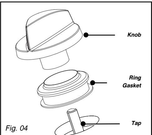
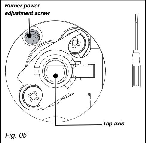
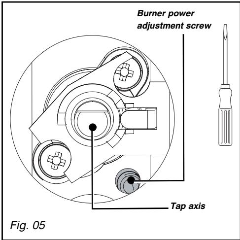
- Adjust the hob connections: they are located underneath the knobs (Fig. 04).
- Proceed one tap at a time.
- Remove the knobs and the gaskets by pulling them up.
- Switching from natural gas to butane/propane gas
- With a small flat-head screwdriver, screw in all the way the brass (yellow) burner power screws(Fig. 05), in a clockwise direction.
- Replace the gaskets and the knobs, paying careful attention to their direction and ensuring that the knobs are pushed in all the way.
- Switching from butane/propane gas to natural gas or to butane-air gas/propane-air gas
- Unscrew the brass (yellow) burner power screws (Fig. 05), using a small flat-head screwdriver, turn twice counterclockwise.
-Replace the knob. - Light the burner in maximum heat mode, then turn down to reduced heat mode.
-
Remove the knob again, then turn the burner power screws clockwise until it reaches the lowest possible setting that does not extinguish the flame.
-
Replace the gasket and knob.
- Make several attempts to shift from the maximum flow rate to the minimum: the flame should not go out; if it does, unscrew the burner power screw so as to obtain good flame retention during these position switches.
- Reposition the burner heads, burner covers and pan supports on the hob.
1 / INSTALLING YOUR APPLIANCE
EN
- Markings on the injectors
MARKINGS ON THE INJECTORS
The adjacent table shows where the injectors are positioned on your appliance according to the type of gas used.
Each number is marked on the injector.
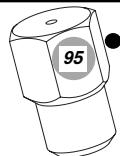
Example:
Injector marking 95
MODELS*
60cm Hob 3 gas burners + 1 electric plate
Natural Gas
Butane gas/Propane
Butane-Air/
Propane Air


137


60 cm Hob 4 gas burners
Natural Gas
Gaz butane/Propane
Butane-Air/
Propane Air


30 cm Hob 2 gas burners
Natural Gas
Butane gas/Propane
Butane-Air/
Propane Air


- See "Description of the Top" chapter
1 / INSTALLING YOUR APPLIANCE
Gas properties
| Appliance intended to be installed in:GB.....................cat : II2E+3+PT.....................cat : II2H3+Hourly rate below:at 15°C under 1013 mbars | ButaneG3028-30 mbar | PropaneG3137 mbar | Gas naturalG2020 mbar | Gas naturalG2525 mbar | Propane-airButane-AirG1308 mbar |
| HIGH-SPEED BURNER | |||||
| Marking engraved on injector(kW) | 782,250,830164 | 782,25161 | 1212,300,870219 | 1212,300,870255 | 2152,400,650336 |
| Nominal heat release rate(kW) | |||||
| Reduced heat release rate (with/without safety)(kW) | |||||
| Hourly rate(g/h) | |||||
| Hourly rate(l/h) | |||||
| SUPER-FAST BURNER | |||||
| Marking engraved on injector(kW) | 883,100,830225 | 883,10221 | 1373,100,870295 | 1373,100,870343 | 3402,900,870406 |
| Nominal heat release rate(kW) | |||||
| Reduced heat release rate (with/without safety)(kW) | |||||
| Hourly rate(g/h) | |||||
| Hourly rate(l/h) | |||||
| SEMI-FAST BURNER | |||||
| Marking engraved on injector(kW) | 621,450,620 | 621,451,45 | 941,500,615 | 941,500,615 | 1651,500,400 |
| Nominal heat release rate(kW) | |||||
| Reduced heat release rate (with/without safety)(kW) | |||||
| Hourly rate(g/h) | |||||
| Hourly rate(l/h) | |||||
| AUXILIARY BURNER | |||||
| Marking engraved on injectorDébito calorifico nominal(kW) | 450,750,30055 | 450,750,35054 | 630,850,35081 | 630,850,35094 | C121,000,350140 |
| Reduced heat release rate (with/without safety)(kW) | |||||
| Hourly rate(g/h) | |||||
| Hourly rate(l/h) | |||||
| HOB 4 GAS BURNERS | |||||
| Total heat release rate(kW) | 7,55549 | 7,55540 | 7,75738 | 7,75858 | 7,801092 |
| Maximum flow rate(g/h) | |||||
| HOB 3+1 ELECTRIC PLATE1500 WWITH SUPER FAST | |||||
| Total heat release rate(kW) | 6,104,444 | 6,104,38 | 6,25595 | 6,25692 | 6,30882 |
| Maximum flow rate(l/h) | |||||
| HOB 2 GAS BURNERS | |||||
| Total heat release rate(kW) | 4,55330 | 4,55325 | 4,60438 | 4,60509 | 4,40616 |
| Maximum flow rate(l/h) | |||||
2 / USING YOUR APPLIANCE
EN
DESCRIPTION OF THE TOP
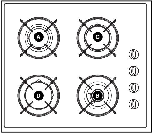
Hob model: 4 gas burners TG*/*
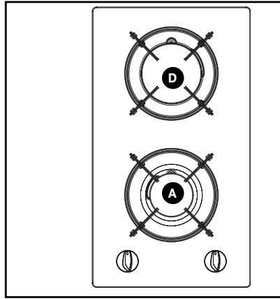
Hob model: 2 gas burners TG*/
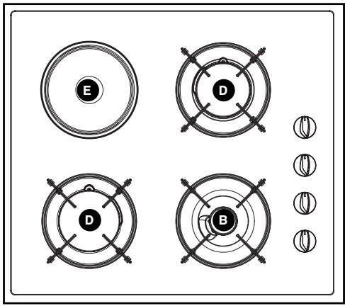
Model: 3+1 electric TG/
A Semi-fast burner 1.50 kW (^)
8 Auxiliary burner 0.85kW^
High-speed burner 2.30 kW ()
Super-fast burner 3.10 kW ()
Electric plate diameter 145 - 1.5 kW
() Power obtained with natural gas G20
2 / USING YOUR APPLIANCE
Each burner is supplied by a tap which can be opened by pressing it and turning it in in a counterclockwise motion.
The "●" point corresponds to closing the tap.
- Choose the desired burner by using the symbols located near the knobs (e.g.: rear left burner ).
Your hob is fitted with a burner-lighting system built into the knobs.
-To light a burner, press on the knob and turn it in a counterclockwise direction to the maximum setting
- Continue to press on the knob to produce a series of sparks until the burner lights.
The setting for more moderate flame intensities are between the symbol and the symbol
Warning
- Hold the knob completely pressed down for a few seconds after the flame appears to trigger the safety system.
HOB WITH GAS SECURITY DEVICE (according to model)
The burner safety measure is a metal rod located directly to the side of the flame.
Each burner is controlled by a tap fitted with a safety system that, in the event of accidental flame extinction (spills, draughts, etc.), quickly and automatically cuts the gas supply and prevents it from being released.
The setting for more moderate flame intensities are between the symbol and the symbol 串
Tip Whe
When a knob becomes difficult to turn, do not force it. Request an emergency service call for the installer.
If the flame goes out accidentally, reignite normally following the starter instructions.
2 / USING YOUR APPLIANCE
EN
COOKWARE TO BE USED WITH GAS BURNERS
- Which burner should you use depending on your cookware?
| Diameter of the cookware | Diameter of the cookware | Use |
| 18 to 28 cm | High-speed | Searing foods |
| 16 to 22 cm | speed | |
| 12 to 20 cm | Semi-fast | Sauces - Reheating |
| 8 to 14 cm | Auxiliary | Gentle simmer |

Warning
-
Adjust the ring of flames so that they do not extend beyond the edges of the cookware (Fig. 01).
-
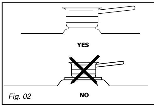
Do not use concave or convex cookware without the appropriate supports (Fig. 02).
- Do not use cookware that partially covers the knobs (Fig. 03).
- Do not leave a gas burner operating with empty cookware.
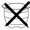
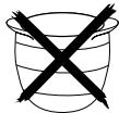
- Do not use heat regulators, toasters, steel meat broilers or stewpots that have feet resting on or touching the glass worktop
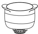
GOOD
Fig. 01
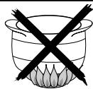
BAD
CONVEX
CONCAVE
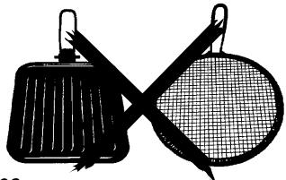
Fig. 02
Fig. 03
2 / USING YOUR APPLIANCE
- MOST SUITABLE COOKWARE TO BE USED WITH THE ELECTRIC PLATE (depending on model)
Use cookware with flat bottoms that are perfectly flush with the surface of the burner: - in stainless steel with a thick, tri-metal or "sandwich" bottom,
-in aluminium with a thick (smooth) bottom,
-- in enamelled steel.
- SWITCHING ON THE ELECTRIC PLATE (depending on the model)
Position the knob on the marking that corresponds to the desired type of cooking (Fig. 01) (see cooking guide at the end of this guide). The cooking zone's power indicator lights up.
Upon first use, allow the plate to heat up with no cookware at maximum power for 3 minutes to harden the coating.

Tip
-
Use cookware of an appropriate size: the diameter of the bottom of the cookware should be equal to or greater than the diameter of the electric cooking plate (Fig. 02).
-
When cooking is nearly finished, turn the knob to the "O" off position to take advantage of the heat accumulated in the plate.
-
Use a lid on your cookware as often as possible to reduce the loss of heat by evaporation.

Warning
Do not operate an electric cooking plate without cookware (except during initial use) or with an empty pot.

Warning
The electric plate will remain hot for a certain time after the knob has been turned to the "O" position. Do not touch this zone because there is a risk of burning.
3 / DAILY CARE OF YOUR APPLIANCE
EN
MAINTAINING YOUR APPLIANCE
| MAINTENANCE...... | WHAT TO DO | PRODUCTS/ACCESSORIES TO BE USED |
| Of the spark plugs and injectors | In the event that the spark plugs become soiled, clean them using a small, hard-bristled brush (non-metallic). The gas injector is located in the centre of the burner in the shape of a dish. Be careful not to obstruct it during cleaning, as this will undermine the performance of your hob. In the event of obstruction, use a safety pin to unclog the injector. | Small, hard-bristled brush. Safety pin |
| Of the pan supports and gas burners | If tough stains occur, use a non-abrasive cream, then rinse with clean water. Carefully wipe each part of the burner before using your hob again. | Gentle scrubbing cream Cleaning sponge |
| Of the electric plate | - The heating plate is protected by a black coating, so you should avoid using any abrasive products. After each use, wipe it down with a thick cloth. - If the plate rusts, remove it and restore the black coating using a commercially available high-temperature restorative product. | Commercially available restorative product. |
| Of the glass worktop | - Clean with warm water and then wipe. For tough stains, use products designed for vitroceramic glass. | Cleaning sponge. Special vitroceramic glass products (e.g.: Cera-clean). |
To keep your appliance in good working order, we recommend that you use Clearit household products.

Professional expertise for the general public
Clearit offers you professional products and adapted solutions for the daily upkeep of your household and kitchen appliances.
You may find them in conventional retail outlets, along with a complete line of by-products and consumables.

Warning
Never clean your appliance while it is in operation. Set all the electric and gas
controls to zero.

Tip
-
It is better to clean the parts of the hob by hand rather than in the dishwasher.
-
Do not use an abrasive sponge to clean your hob.
- Do not use steam cleaning.
4 / SPECIAL MESSAGES, DIFFICULTIES
EN
DURING OPERATION
| YOU OBSERVE THAT: | WHAT YOU SHOULD DO: |
| · Lighting the burners: There are no sparks when you press the knobs. | · Check the electrical connection of your appliance. · Check that the spark plugs are clean · Check that the burners are clean and properly assembled · If the hob is attached to the work top, check that the mounting brackets are not deformed. · Check that the gaskets under the knobs are not coming out of their lodging. |
| · When you press on a knob, there are sparks on all of the burners simultaneously. | This is normal. The lighting function is centralised and controls all of the burners simultaneously. |
| · In reduced heat mode, the burner goes out or the flames remain high. | · Avoid strong air currents in the room. · Check that the gas type being used corresponds to the injectors installed (Read about markings on the injectors in the "Changing the Gas Supply" chapter). Reminder: The cooking hobs are sold pre-set for use with network gas (natural gas). · Check that the burner power screws are properly set (See the "Changing the Gas Supply" chapter). |
| · The flames look irregular or uneven. | · Check the cleanliness of the burners and injectors under the burners, the assembly of the burners, etc... · Check that there is enough gas in the bottle. |
| · During cooking, the knobs become hot. | · Use small saucepans on the burners located closest to the knobs. Large cookware should be used on the largest burners, which are farther away from knobs. Properly place the saucepan in the centre of the burner. It should not spill over onto the knobs. |
| If the hob has a gas safety device: during lighting, the flames light, then go out as soon as the knob is released. | · Press firmly down on the knobs and hold them down for a few seconds after the appearance of flames. · Check that the parts of the burner are correctly mounted. · Check that the gaskets under the knobs are not coming out of their lodging. · Avoid strong draughts in the room. · Light your burner before placing your saucepan on it. |
5 / COOKING CHART
- GAS COOKING GUIDE
| PREPARATIONS | TIMES | SUPER FAST | FAST | SEMI-FAST | AUXILIARY | |
| SOUPS | BouillonsThick soups | 8-10 minutes | X | X | ||
| FISH | Court-bouillonGrilling | 8-10 minutes | X | |||
| 8-10 minutes | X | |||||
| SAUCES | Hollandaise, béarnaiseBéchamel, aurore | 10 minutes | X | X | ||
| X | X | |||||
| VEGETABLES | Endives, spinachCooked peasProvençale tomatoesGolden brown potatoesPasta | 25-30 minutes15-20 minutes | XX | X | ||
| X | X | |||||
| X | X | |||||
| X | X | |||||
| MEATS | SteakBlanquette, Osso-buccoSauteed poultry breastsTournedos | 90 minutes10-12 minutes10 minutes | XX | X | ||
| X | X | |||||
| X | X | |||||
| FRIEDFOODS | French friesBeignets | X | ||||
| X | ||||||
| DESSERTS | Rice puddingFruit compoteCrêpesChocolateCrème anglaiseCoffee (small percolator) | 25 minutes | X | X | X | X |
| 3-4 minutes | X | X | ||||
| 3-4 minutes | X | |||||
| 10 minutes | X | X |
ELECTRICAL COOKING GUIDE
| PREPARATIONS | VERY HIGH 6 | HIGH 5 | MEDIUM 34 | GENTLE SIMMER 2 | KEEP WARM 1 | |
| SOUPS | Broths | X | X | X | ||
| Thick soups | X | X | ||||
| FISH | Court-bouillon | X | X | X | ||
| Frozen foods | X | |||||
| SAUCES | Thick with butter | X | X | |||
| VEGETABLES | Endives, spinach | X | X | |||
| Dry vegetables | ||||||
| Boiled potatoes | X | X | ||||
| Golden-brown potatoes | X | X | ||||
| MEATS | Steak | X | ||||
| Grilled food | X | |||||
| FRYING | French fries | X | ||||
| OTHER | Compotes | X | X | |||
| Pancakes | X | |||||
| Custard | ||||||
| Melted chocolate preserves | X | |||||
| Milk | X | X | X | |||
| Pasta | ||||||
| Rice pudding | X | |||||
| Keep warm | X |
Brandt

02
—Retire as grelhas, os chapéus e as cabecas de todos os bicos.
Any maintenance on your equipment should be undertaken by:
either your dealer,
- or another qualified mechanic who is an authorized agent for the brand appliances.
When making an appointment, state the full reference of your equipment (model, type and serial number). This information appears on the manufacturer's nameplate attached to your equipment.
In the unlikely event of there being a problem with your appliances please call the number below quoting the model number of your appliance - this can be found on the ratings plate. Our trained staff are available to advise or book a service call with one of our authorized service agents.
Service lines
Mon - Sat 9am - 6pm
Sun 10am - 4pm
Cooking
0115 976 6937
For any other information on our products please contact us at:
Brandt UK
Intec 4
Wade Road
Basingstoke
RG4 8NE
Tel: 01256 308000
www.Brandtuk.com
6 / SERVICOS AUTORIZADOS
PT