
18DLT x2 - Switch Norgren - Free user manual and instructions
Find the device manual for free 18DLT x2 Norgren in PDF.

User questions about 18DLT x2 Norgren
0 question about this device. Answer the ones you know or ask your own.
Ask a new question about this device
Download the instructions for your Switch in PDF format for free! Find your manual 18DLT x2 - Norgren and take your electronic device back in hand. On this page are published all the documents necessary for the use of your device. 18DLT x2 by Norgren.
USER MANUAL 18DLT x2 Norgren
The data specified above only serve to describe the product. No statements concerning a certain condition or suitability for a certain application can be derived from our information. The given information does not release the user from the obligation of own judgement and verification. It must be remembered that our products are subject to a natural process of wear and aging.
This document, as well as the data, specifications and other informations set forth in it, are the exclusive property of Norgren GmbH. Without their consent it may not be reproduced or given to third parties.
Subject to modifications.
Printed in Germany
These instructions were originally generated in German.
Order no: 7503568.99.08.2010
DE/EN/FR/IT/ES/
7503568.99.08.2010
Revision: A
DE/EN/FR/IT/ES
Deutsch
70736 Fellbach, Germany
Tel: +49 711 5209-0
Fax:0711/5209-614
The data specified above only serve to describe the product. No statements concerning a certain condition or suitability for a certain application can be derived from our information. The given information does not release the user from the obligation of exercising judgement and verification. It must be remembered that our products are subject to a natural process of wear and ageing.
This document, as well as the data, specifications and other information presented in it are the sole property of Norgren GmbH. It may not be reproduced or given to third parties without their consent.
Subject to change without notice.
Printed in Germany
These instructions were originally written in German.
Order no: 7503568.99.08.2010
DE/EN/FR/IT/ES/
7503568.99.08.2010
Version: A
DE/EN/FR/IT/ES
English
1 About these instructions
These instructions contain important information required for safe and proper installation, operation, maintenance and simple repair of the 18D-LT x2 pressure switch.
Read these instructions and especially the Section 2 'For your safety' before installing the 18D-LT x2 and connecting it to the compressed air supply.
Standards followed:
We hereby declare that this product complies with the following standards or normative
documents:
EMC as per 2004/108/EC
- Emitted interference EN 61000-6-3 (2007)
Interference resistance EN 61000-6-2 (2005)
Other applicable documents
Technical data and dimensions according to the main catalogue
2 For your safety
The 18D-LT x2 has been manufactured according to current technical standards and recognised
safety-related regulations. Nonetheless, failure to comply with the general safety instructions, warnings before procedures in these instructions could result in personal injury and property damage.
Therefore you should read these instructions thoroughly before working with the 18D-LT x2.
- Keep the instructions available to all users at any time.
Always provide third parties with these operating instructions together with the 18D-LT x2.
Intended use
Use the 18D-LT x2 only for monitoring pressure values in accordance with
the technical specifications in industrial environments
Adhere to the performance limits indicated in the specifications (see data sheet 5.11.006). Intended use includes having read and understood these instructions and
and especially the section 'For your safety'.
Non-intended use
Non-intended use includes
using the 18D-LT x2
for areas of application not listed in these instructions,
under operating conditions other than those described in these instructions.
Qualification of personnel
Exhaust guard installation, removal and startup require basic electrical and pneumatic knowledge as well as familiarity with the respective special terminology. Installation, removal, startup and operation must therefore only be performed by a electrician or pneumatics specialist or a trained person
with instructions and supervision from a specialist.
Specialists are capable of assessing the work assigned to them, recognising possible hazards and implementing the appropriate safety measures based on their professional training, knowledge and experience, as well as their knowledge of the relevant specifications. The specialist must comply with the regulations relevant to the specific area.
Warnings in these instructions
These instructions include warnings beside procedural instructions for procedures with risk of personal injury or property damage.
The described hazard prevention measures are to be observed.
Signal word
CAUTION
Indicates a potentially dangerous situation which can lead to property damage if not avoided.
WARNING
Indicates a potential hazard which can lead to severe injuries or death if not avoided.
You must observe the following
General information
Please pay attention to the regulations for safety, accident prevention and environmental protection in the country of use and at the workplace.
- The 18D-LT x2 must not be modified nor converted. Failure to comply with these instructions as well as changes to the unit negate any liability on the part of the manufacturer; the warranty for the unit and accessories is voided.
- Use the 18D-LT x2 only within the performance range specified in the technical data.
All configuration of the 18D-LT x2, all installation, dismantling and startup work must be performed only by trained, qualified personnel.
- Do not disconnect cables and hoses on systems which carry live voltage or are under pressure!
- Do not subject the pressure switch to bending, torsion or shock.
Pressure measurement on the 18D-LT x2 only works correctly if suitable connection cables are used.
For installation and startup
The warranty applies only to the the configuration delivered. It is void if the installation is not correct.
Always ensure that the relevant part of the system does not carry live voltage and is not under pressure before the 18D-LT x2 is installed or removed.
- Ensure that the connected compressed air lines do not contain dirt particles and that no liquids enter the device along the connected lines.
Use only threaded inserts which seal to the outside (maximum screw-in depth 9 mm).
- Do not install units with obvious damage and replace defective units promptly.
Operation
- Operate the 18D-LT x2 only under the conditions listed in the specifications and limit value information. Failure to do so compromises the operational reliability and safety of the switch and risks impaired function or destruction.
- Replace the 18D-LT x2 immediately if malfunctions occur.
Information about the device's year of manufacture: in the five-character date code on the type plate, the first two characters specify the decade and the year, with A representing the years 2000 to 2009 and B representing the years 2010 to 2019 (example: B0111 = year 2010).
Please note the following special conditions:
The permitted environmental and fluid temperature can be found on the corresponding technical data sheet.
It must be ensured that an impermissibly high device temperature, which can occur during brief cyclical pressure fluctuations, is prevented.
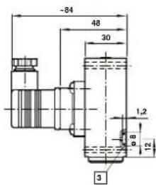
If sudden pressure changes and pressure spikes occur with liquid fluids, an absorption prechamber must be connected upstream. Order code 0574773. With a lateral flange (roughness of the flange surface Rt < 12mm the 5× 1.5 O-ring (order code 0664098) is part of the delivery. The supporting thread length is at least 7.5mm . The maximum diameter of the pressure connection hole is 3mm .
- Please note that the connectors must not be disconnected under voltage!
3 Delivery contents
Delivery includes:
1 18D-LT x2 pressure switch
- 1 equipment socket
- 1 operating manual for the 18D-LT x2
- attachment screws are not included with delivery
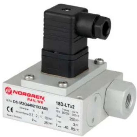
4 Unit description
The 18D-LT x2 pressure switch functions as a switch in signal, control and settling circuits. It monitors the connected relative pressure and depending on the model of 18D-LT x2 and the set switching points or functions converts it to an analogue current or voltage signal.
5 Installation
CAUTION

Risk of injury from uncontrolled operation
If the 18D-LT x2 carries electric voltage and/or pressure during installation, uncontrolled reactions can result which lead to injuries or damage to the system.
Always ensure that the relevant part of the system does not carry live voltage and is not under pressure before the 18D-LT x2 is connected pneumatically or electrically.
The tightening torque for the attachment screws is 1.6 + 0.4Nm . Install in the open only with sufficient protection against critical environmental conditions (such as atmospheres which are corrosive or contain salt).
Connecting compressed air
CAUTION

Damage to the device
The use of incorrect connection fittings or failure to comply with limit values can lead to device damage. Stay within the limit values for pressure and temperature (see specifications data sheet 5.11.006).
Do not screw in any connection fittings with conical threads! Use only connection fittings which are axially sealed on the outside flange with a maximum screw-in depth of 9mm
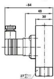
Construct the counter piece for the plug-in connection with a suitable Thread.
Scale drawing of connection: Inside thread
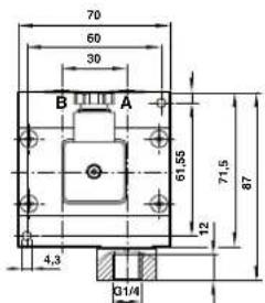
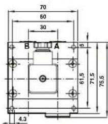
Scale drawing of connection: Flange
CAUTION

Risk of injury from pressure hoses which become disconnected
Unsuitable pressure hoses on the 18D-LT x2 can become disconnected under pressure, cause injuries and damage the 18D-LT x2.
Use only the pressure hoses specified by Norgren.
Connecting the 18D-LT x2 electrically
- Connect the equipment socket carefully to ensure safety class IP 65.
Please note the pin assignment. - Use shielded cables if the 18D-LT x2 is exposed to strong electromagnetic fields.
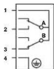
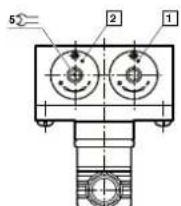
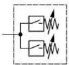
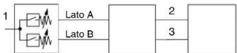
Switch function drawings
Switch functions as per DIN EN 175301-803 (DIN 43650) Form A
One single-pin microswitch (converter)
Switch A: NO Figure 1
Contacts 1-2:
With increasing pressure contact closes
Switch B: NC
Contacts 1-3:
With decreasing pressure contact closes
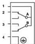
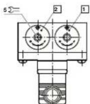
Switch A: NC Figure 2
Contacts 1-2:
With decreasing pressure contact closes
Switch B: NO
Contacts 1-3:
With increasing pressure contact closes
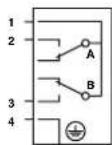
Switch A: NC Figure 3
Contacts 1-2:
With decreasing pressure contact closes
Switch B: NC
Contacts 1-3:
With decreasing pressure contact closes
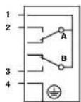
Switch A: NO Figure 4
Contacts 1-2:
With increasing pressure contact closes
Switch B: NC
Contacts 1-3:
With increasing pressure contact closes
1 Switch A
2 Switch B
1 Switch A
2 Switch B
3 O-ring, 5 x 1.5
English
6 Startup and operation
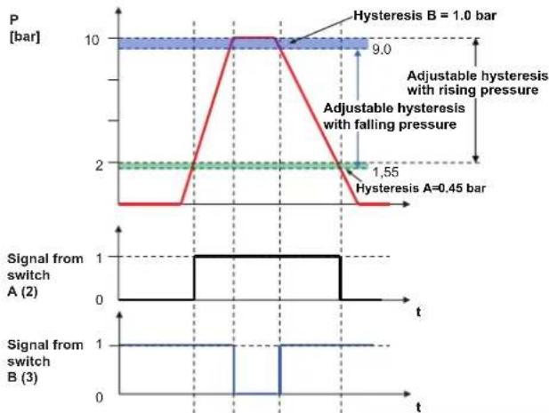
Setting the switching points
The switching points are freely adjustable in the pressure switching range. Switching points should ideally be in the middle of the pressure switching range. Do not use the limit value (corresponds to the test pressure) during operation. To set the switching points, loosen lock screw 5. The upper and lower switching points are set by turning adjustment screw 4 (turn to the right for rising and to the left for falling pressure). The adjustment value can be checked with a manometer. To complete the procedure, tighten lock screw 5.
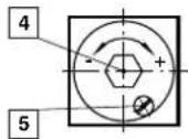
4 Adjustment screw for switch point 5 Lock screw
Putting the 18D-LT x2 into operation
Before putting the system into operation, the following work must be performed and completed:
The 18D-LT x2 must be fully installed and connected.
The configuration and defaults must be set.
Putting the 18D-LT x2 into operation:
- Apply operating voltage.
- Vent the part of the system to which the 18D-LT x2 is connected.
WARNING

Dangerous system operating conditions from incorrect settings on the 18D-LT x2 or operating voltage outside the limits. There is a risk of injury and damage to the system from uncontrolled operating conditions of the system.
Do not use any improper settings on the 18D-LT x2 prior to or during operation.
Replace defective pressure switches immediately.
Do not disconnect the 18D-LT x2 pressure switch from its voltage source while it is in operation!
7 Removal and replacement
Removing the 18D-LT x2
CAUTION

The system is under high pressure. There is a risk of injury and damage to the system from uncontrolled operating conditions of the system. In the part of the system in which the 18D-LT x2 is installed there must be no live voltage or pressure before commencing removal.
- Always ensure that there is neither voltage nor pressure in the relevant part of the system.
- Loosen and remove all connections.
- Remove the pressure switch from the pressure connection (thread connection) using a fork spanner or pull the 18D-LT x2 straight from the plug connection.
8 Maintenance and repair
The pressure switches require no maintenance. If the devices fail or malfunction during operation for unknown reasons, they must be replaced.
Defective microswitches or other components cannot be repaired or replaced.
Pressure switches that show signs of damage must not be installed or must be replaced. The pressure switches may not be used as levers. If they are exposed to special types of external stresses, additional safety measures are required.
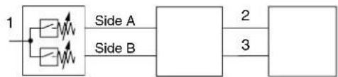
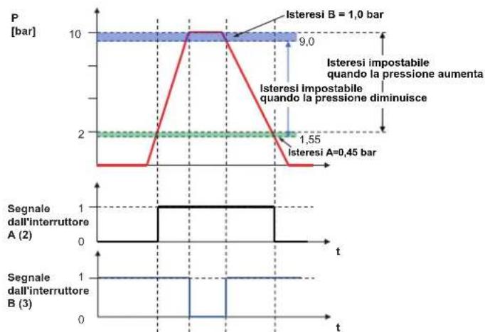
Example: 18D LTx2
Side A: Pressure range 0.2 to 2 bar Side B: Pressure range 1.0 to 10 bar
9 Specifications
The specifications are found in the corresponding data sheet 5.11.006.
Applies to all pressure switches of the series 18D-LT x2.
Pneumatic connection:
G1/4 inside or 1 / 4 NPT, flange
Storage temperature:
-20°C to +85°C
Environmental temperature:
-40^ C to +85^ C ;
Medium temperature:
-40°C to +85°C
Temperature at the switching element:
-40^ to +85^
Medium:
for inert, gaseous and liquid, non-flammable gases (40 m grade filtered compressed air fineness)
Pressure switch ranges:
0.2 to 2 bar; 0.5 to 8 bar; 1.0 to 10 bar; 1.0 to 16 bar.
Installation position : any
Shock and vibration resistant as per
EN 61373, Category 1, Class A and B
Electrical connection:
DIN EN 175301-803 (DIN 43650) Form A
Overpressure safety: 26 bar
Switch element functions:
microswitch (change-over contact)
Safety class:
(DIN EN 60 529/09.2000)
IP65, with installed connector plug
Material:
Housing, aluminium
Seals: EPDM; VMC (silicone)
10 Disposal
Dispos of packaging and used parts as required by the regulations in the country of use.
MANOSTAT
18D-LT x2
Bedienungsanleitung · Operating instructions · Mode d'emploi · Istruzioni d'uso · Instrucciones de service · Bruksanvisning
Norgren GmbH, site de Fellbach
Stuttgarter StraBe 120
The data specified above only serve to describe the product. No statements concerning a certain condition or suitability for a certain application can be derived from our information. The given information does not release the user from the obligation of own judgement and verification. It must be remembered that our products are subject to a natural process of wear and aging.
This document, as well as the data, specifications and other informations set forth in it, are the exclusive property of Norgren GmbH. Without their consent it may not be reproduced or given to third parties.
Subject to modifications.
Printed in Germany
These instructions were originally generated in German.
Order no: 7503568.99.08.2010
DE/EN/FR/IT/ES/
7503568.99.08.2010
Version : A
DE/EN/FR/IT/ES
Français
Joint: EPDM; VMC (silicone)
10 Mise au rebut
The data specified above only serve to describe the product. No statements concerning a certain condition or suitability for a certain application can be derived from our information. The given information does not release the user from the obligation of own judgement and verification. It must be remembered that our products are subject to a natural process of wear and aging.
This document, as well as the data, specifications and other informations set forth in it, are the exclusive property of Norgren GmbH. Without their consent it may not be reproduced or given to third parties.
Subject to modifications.
Printed in Germany
These instructions were originally generated in German.
Order no: 7503568.99.08.2010
DE/EN/FR/IT/ES/
7503568.99.08.2010
Revision: A
DE/EN/FR/IT/ES
Italiano
Lato B: Range pressione 1,0 ... 10 bar
9 Dati tecnici
The data specified above only serve to describe the product. No statements concerning a certain condition or suitability for a certain application can be derived from our information. The given information does not release the user from the obligation of own judgement and verification. It must be remembered that our products are subject to a natural process of wear and aging.
This document, as well as the data, specifications and other information set forth in it, are the exclusive property of Norgren GmbH. Without their consent it may not be reproduced or given to third parties.
Subject to modifications.
Printed in Germany
These instructions were originally generated in German.
Order no: 7503568.99.08.2010
DE/EN/FR/IT/ES/
7503568.99.08.2010
Revision: A
DE/EN/FR/IT/ES