Caravanman 65 Professional GPS V2 - Receiver MEGASAT - Free user manual and instructions
Find the device manual for free Caravanman 65 Professional GPS V2 MEGASAT in PDF.

| Product Type | Motorized satellite antenna with GPS receiver |
| Brand | MEGASAT |
| Model | Caravanman 65 Professional GPS V2 |
| Number of users | 2 users (connections for 2 receivers) |
| Satellite input frequency | 0.7 ~ 12.75 GHz |
| Frequency band | Ku-Band (10.7 GHz - 12.75 GHz) |
| Antenna gain | 35.1 dBi @ 11.8 GHz |
| Reception power | 45 dBW |
| Motor | DC motor, 2 axes |
| Rotation angle range | 360° (20° per second) |
| Tilt angle range | 0° ~ 75° (10° per second) |
| Programmed satellites | Astra 1 (19.2° E), Astra 2 (28.2° E), Astra 3 (23.5° E), Hotbird (13° E), Thor (0.8° W), Eutelsat 9B (9° E) |
| Input voltage | DC 12 ~ 24 V, 10 A |
| Operating temperature | -15°C ~ +50°C |
| Storage temperature | -30°C ~ +70°C |
| Antenna dimensions (retracted) | 66.0 x 20.0 x 87.0 cm (L x H x D) |
| Antenna weight | 12.1 kg |
| Control unit dimensions | 18.0 x 4.0 x 13.0 cm (L x H x D) |
| Special features | Integrated GPS receiver, automatic skew, control via Bluetooth app, firmware update via USB or smartphone, error indication via LED |
| Maintenance and cleaning | Clean the mounting surface with a suitable cleaner and a non-woven cloth; after gluing, avoid adhesive leaks. For the antenna, remove snow or ice before use. |
| Safety | Do not open the antenna cover (loss of warranty). Installation by an authorized dealer. The system retracts automatically when the vehicle starts. Do not use while moving. Mounting temperature between +5°C and +25°C. Observe the total height of the vehicle. |
| General information | Manual available in several languages. Mandatory update before first use via the Megasat 65/85 V2 app. Support via www.megasat.tv. |
Frequently Asked Questions - Caravanman 65 Professional GPS V2 MEGASAT
User questions about Caravanman 65 Professional GPS V2 MEGASAT
0 question about this device. Answer the ones you know or ask your own.
Ask a new question about this device
Download the instructions for your Receiver in PDF format for free! Find your manual Caravanman 65 Professional GPS V2 - MEGASAT and take your electronic device back in hand. On this page are published all the documents necessary for the use of your device. Caravanman 65 Professional GPS V2 by MEGASAT.
USER MANUAL Caravanman 65 Professional GPS V2 MEGASAT
natural_image
White satellite dish with 'MEGASAT' branding on its side, mounted on a base (no additional text or symbols visible)Caravanman 65 / 85 Premium V2 Caravanman 65 / 85 Professional GPS V2
Bedienungsanleitung
WICHTIG!!!
natural_image
Purple cloth cleaning a white surface with a blue hand partially visible (no text or symbols)natural_image
Close-up of a white mechanical device with a wooden pencil inserted, placed on a flat surface with dashed lines indicating alignment (no text or symbols visible)3.2 Klebeanleitung
natural_image
Pure diagram of a U-shaped pipe or tube inside a dashed diamond shape on a white surface (no text or symbols)natural_image
Close-up of a white plastic electrical plug with two metallic fittings (no text or symbols visible)
natural_image
Mechanical assembly diagram showing a component being inserted into a housing, with a red arrow indicating the process (no text or symbols present)natural_image
3D model of a device showing internal components before and after assembly, with blue arrows indicating direction (no text or symbols)natural_image
Close-up of a black electronic device with ventilation grille, ports labeled PWR and CON, and a USB port (no readable text beyond labels)
natural_image
Black USB flash drive with a blue upward arrow above it (no text or symbols)www.megasat.tv/support/downloads
Notizen
H11026-04
natural_image
White satellite dish with 'MEGASAT' branding on its side, mounted on a base (no additional text or symbols visible)Caravanman 65 / 85 Premium V2 Caravanman 65 / 85 Professional GPS V2
user manual
IMPORTANT!!!
Please carry out a firmware update before using the antenna for the first time, with the „Megasat 65/85 V2“ app, perform a firmware update!
1. Introduction
1.1 General information....03
1.2 Safety instructions....03
1.3 Delivery 03
2. Control unit and control panel
2.1 Control unit front side 04
2.1 Control unit rear side....04
2.3 Control panel 05
3. Mounting and installation
3.1 Mounting on the roof of the vehicle....06
3.2 Gluing instructions 07
3.3 Mounting the roof outlet 08
3.4 Connection of the connecting cables 09
4. Preparations for commissioning
4.1 Choice of location....10
4.2 Manual skew adjustment.... 10
5. Startup and operation
5.1 Starting up the system.... 12
5.2 Select another satellite.... 12
5.3 Turn off the system....12
6. Footprint 13
7. Control via the app
7.1 Installing the app on the mobile device....14
7.2 Connection with the control unit....14
7.3 Explanation of the app.... 15
8. Troubleshooting .... 18
9. Firmware-Update
9.1 Update via USB device 20
9.2 Update via the smartphone or tablet....20
10. Specifications 21
11. Dimensions
11.1 Caravanman 65....22
11.2 Caravanman 85....23
1.1 General information

Attention: Improper handling can lead to serious damage to this device. The responsible persons may also be held liable for any further damage to the device resulting from this.
Note: Read the user manual carefully before you start the installation. If you have already installed similar products, the procedure may not be the same for this product.
1.2 Safety instructions
- Do not open the cover of the antenna. Opening the housing will void the warranty. In case of repair, please contact your specialist dealer.
- The installation of the system should be performed by an authorized dealer. Installation by unqualified persons may cause damage to the antenna or the vehicle.
- During installation, you should also connect the engine control cable to the vehicle's ignition plus. When the vehicle's engine is started, the system will automatically retract the antenna and then switch it off. Nevertheless, check that the antenna is retracted before each journey!
- This system is not suitable for use while the vehicle is in motion. Use while the vehicle is in motion may cause damage to the vehicle and endanger safety.
- When mounting the control unit, make sure that no accumulated heat is generated. The air around the housing must always be able to circulate.
- If the antenna is covered with snow or ice, do not operate the system. It may otherwise cause permanent damage to the system.
- The antenna unit mounted on the vehicle increases the overall height of the vehicle. Always pay attention to the total height when driving through a bridge, wooded road etc.
1.3 Delivery
- Antenna unit incl. mirror
• Control unit incl. control panel - Base plate for mounting
-
Roof duct
-
7 m and 0,30 m control cable
- 7 m and 0,30 m coaxial cable
- User manual
2. Control unit ans control panel
2.1 Control unit front side
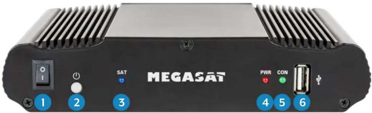
text_image
MEGASAT 1 2 3 SAT PWR CON 4 5 6- I/O: Main switch for power supply.
- ⏻: Standby button and key for connection to a mobile device via Bluetooth®.
- SAT: LED flashes long during satellite search, flashes fast during fine adjustment.
- PWR: LED lights up when the control unit is ready for operation.
- CON: LED lights up if there is a connection to the satellite.
- USB: USB port for future firmware updates.
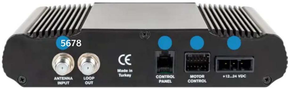
2.2 Control unit rear side
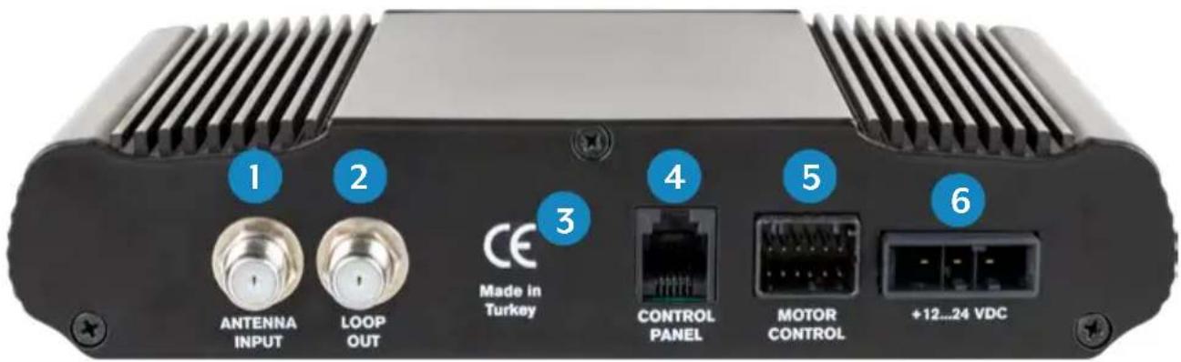
text_image
1 2 CE Made in Turkey ANTENNA INPUT LOOP OUT CONTROL PANEL MOTOR CONTROL +12...24 VDC- ANTENNA INPUT: LNB input for the LNB cable from the antenna.
- LOOP OUT: LNB output to satellite receiver or TV with integrated receiver.
- Bluetooth ^® receiver for connecting to a mobile device.
- CONTROL PANEL: Connection for the control unit.
- MOTOR CONTROL: Connection for the control cable to the antenna.
- +12...24 VDC: Connection to power supply (12\~24 Volt DC).
2. Control unit ans control panel
2.3 Control panel
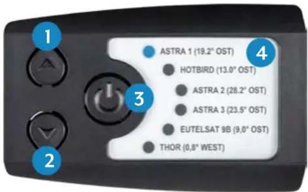
text_image
ASTRA 1 (19.2° OST) HOTBIRD (13.0° OST) ASTRA 2 (28.2° OST) ASTRA 3 (23.5° OST) EUTELSAT 9B (9,0° OST) THOR (0,8° WEST)- p: Switches up to a satellite.
- q: Switches down to a satellite.
- I/O: Switches the control unit to standby and retracts the antenna.
- Satellite list: Displays the currently selected satellite.
3. Mounting and installation
3.1 Mounting on the roof of the vehicle
-
Provide a suitable workplace. A garage or hall is better than an outdoor place. The ambient temperature for mounting must be between +5°C and max. +25°C. Do not work directly in the sun. Observe the work regulations when handling chemical products. Ensure the necessary working hygiene.
-
Make sure that the roof of your vehicle is sufficiently stable. For If the stability of the roof is insufficient or doubtful, an approx. 2 mm thick sheet metal of approx. 100 x 100 cm must be fastened to the outer skin of the roof. For further information please contact your vehicle manufacturer.
-
Check that all parts are present.
-
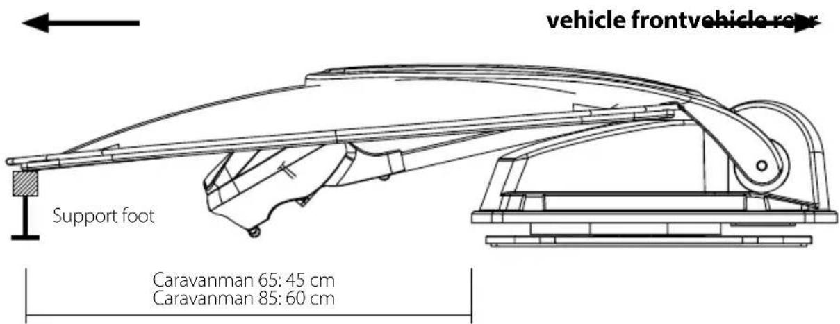
Place the antenna at the later installation site and align it so that the mirror and the LNB unit point towards the rear of the vehicle. Make sure that the mounting surface is flat and that there are no roof structures in the way. The minimum distance to an air conditioner should be 30 cm.
text_image
vehicle frontvehicle rear Support foot Caravanman 65: 45 cm Caravanman 85: 60 cm-
Clean the mounting surface with a suitable cleaner and a fleece cloth to remove dirt and impurities.
-
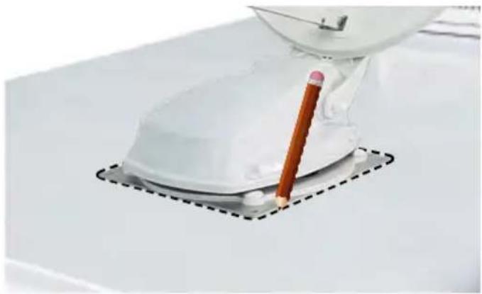
Then mark the antenna base (mounting plate) with a pen.

natural_image
Purple cloth cleaning a white surface with a blue hand partially visible (no text or symbols)3. Mounting and installation
- Slightly roughen the drawn surface with sandpaper (120 grit) and clean the surface again with the cleaner and allow the cleaner to flash off for approx. 10 minutes.
ATTENTION: Do not touch the surfaces afterwards!
natural_image
Close-up of a white mechanical device with a pencil inserted, placed on a flat surface with dashed lines indicating alignment (no text or symbols visible)3.2 Gluing instruction
-
Prepare the adhesive for assembly.
-
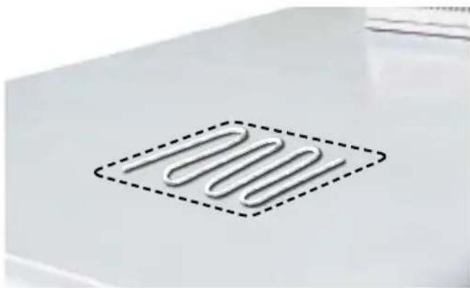
Now apply the adhesive to the marked area of the roof in serpentine lines so that the adhesive can cure evenly over the entire surface.
-
Now immediately (within 5 minutes of applying the adhesive) place the antenna on the marked field. Press the foot lightly and evenly on and
text_image
1000fix the antenna so that it does not slip, e.g. with an adhesive tape. After pressing, there must be at least 2 mm of adhesive between the antenna foot and the surface. The adhesive is cured after max. 48 hours at +18°C and a relative humidity of 50%. If the air humidity is lower during installation, spray some water into the air again and again after sticking the adhesive in the vicinity of the antenna.
-
Remove the possibly leaked adhesive immediately with a spatula or similar and clean the contaminated surfaces with the cleaner and a fleece cloth.
-
For safety reasons, you can also attach the antenna base. Drill through the existing holes in the antenna foot into the roof of your vehicle and fix it with a screw and lock nut. To prevent the freshly glued base from slipping, wait with this work until the adhesive has hardened.
-
After the complete assembly and hardening of the adhesive, a silicone joint can be drawn around the antenna base.
3.3 Mounting the roof outlet
3.3 Mounting the roof outlet
If there is no existing roof lead-through that can be used, look for a suitable place (preferably in the slipstream behind the antenna) on the vehicle roof. Make sure that water and moisture (e.g. rain or splash water) do not penetrate the borehole. Make sure that the cables are not bent too much to avoid signal loss and damage to the cable (smallest bending radius max. 5-7 cm).
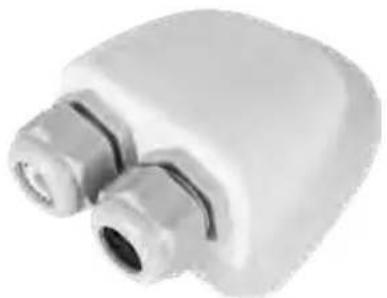
The roof grommet is glued to the vehicle roof like the antenna itself.
After mounting the bushing, feed the cables through the respective openings and then tighten the clamping screws.
natural_image
Close-up of a white plastic electrical plug with two metallic connectors (no text or symbols visible)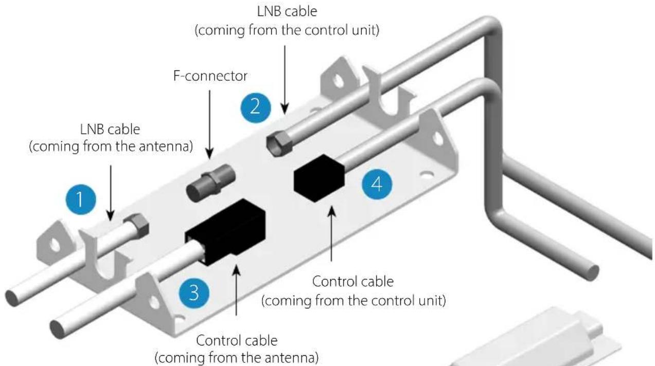
text_image
LNB cable (coming from the control unit) F-connector LNB cable (coming from the antenna) Control cable (coming from the control unit) Control cable (coming from the antenna)To install the weather protection housing for the cable plug connection, glue the base plate to a suitable location on your vehicle. Now place the cover on the base plate and fasten it with the enclosed screws. If necessary, seal both openings with the weatherproof of silicone.
natural_image
Diagram showing a mechanical assembly with a red arrow indicating a process or operation (no text or symbols present)3. Mounting and installation
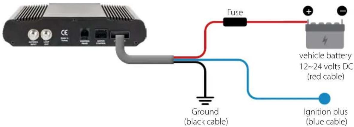
3.4 Connecting the connecting cables
Connections on the roof:
- Connect the coaxial cable (1) to the coaxial cable (2) with the F-connector.
- Connect the control cable (3) to the control cable (4).
- Carefully place both cables through the openings of the weatherproof housing.
- Guide both cables through the roof grommet into the interior of the vehicle and tighten the cable gland.
Connections inside the vehicle:
- Connect the coaxial cable (2) to the antenna input (5) on the control unit.
- Connect the 30 cm cable to the receiver or TV.
- Connect the control unit to the input (6) on the control unit.
- Connect the control cable (4) to the input (7) on the control unit.
- Connect the vehicle's power supply to the control unit (8).
text_image
5678 ANTENNA INPUT LOOP OUT CE Made in Turkey CONTROL PANEL MOTOR CONTROL +12...24 VDCConnecting the power supply:
text_image
Fuse vehicle battery 12~24 volts DC (red cable) Ground (black cable) Ignition plus (blue cable)4. Preparations for commissioning
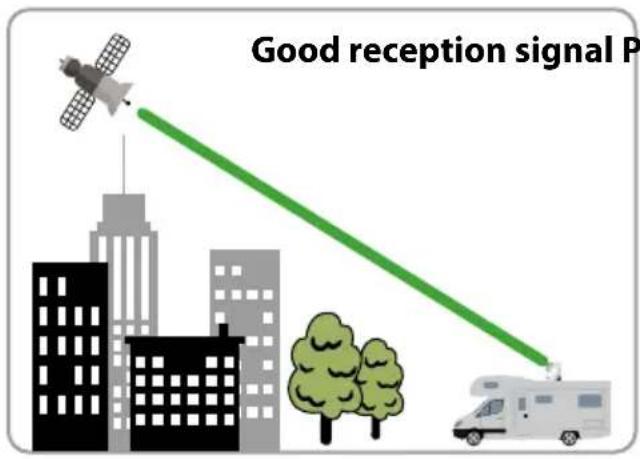
4.1 Choice of location
Objects such as trees, bridges and large houses located at the satellite's angle of incidence cause the signal to be lost. Heavy rain, clouds, snow or ice can affect the reception quality. If the satellite signal is lost due to severe weather conditions, the current program of the receiver will be stopped (the image will freeze or disappear). When the weather conditions allow good reception again, the TV picture will be restored (No new search process necessary).
text_image
Good reception signal P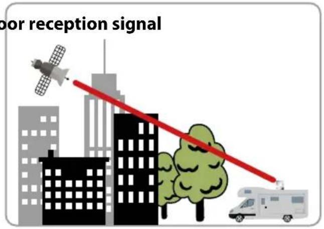
text_image
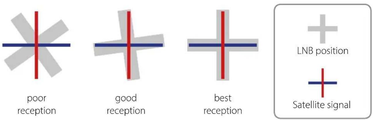
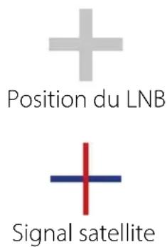
bar reception signal4.2 Manual skew setting
Signals in vertical (red) and horizontal (blue) lines have an offset of exactly 90^ to each other. Due to the different positions of the satellites, depending on your location, it is possible that the signals do not hit the LNB exactly vertically and horizontally. To adjust this, you must place the LNB in the correct position to the transmitted signal. This adjustment to the LNB is called a „skew setting“. The following figure shows the optimal adjustment of the LNB. The better the match, the better the reception.
text_image
poor reception good reception best reception + LNB position + Satellite signal4. Preparations for commissioning

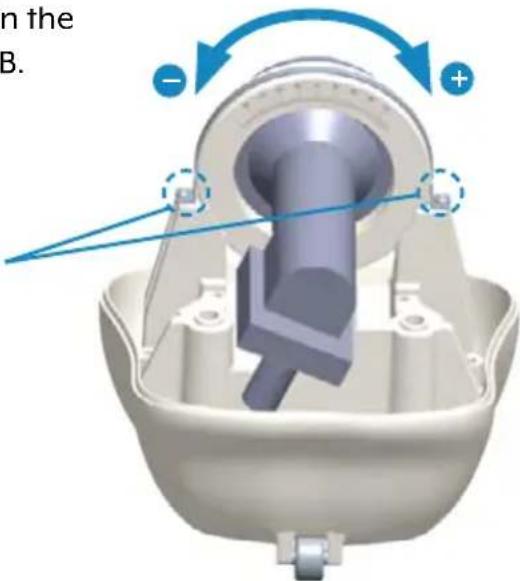
You only have to make the following settings for the Caravanman 65 / 85 Premium V2 (without Auto Skew)!
If you are located in Central Europe, no skew settings are usually necessary. To adjust the skew setting nevertheless, proceed as follows:

natural_image
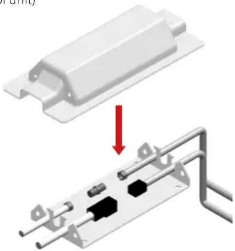
3D model of a device showing internal components before and after assembly, with blue arrows indicating direction (no text or symbols)-
Loosen the screws on the underside of the LNB.
-
Loosen the two screws on the LNB holder.
text_image
n the B.-
Open the LNB cover.
-
Now turn the LNB to the left or right to set the correct degree.
-
Then retighten the screws and close the LNB cover.
Overview of Skew settings for european capitals
| Country Town Astra 1 Astra 2 Astra 3 Hotbird Thor Eutelsat 9B | |||||||
| Bulgaria Sofia +11.4 | +1.7 | +6.8 | +11.0 | +24.0 | +15.0 | ||
| Denmark | Copenhagen | +2.5 | -3.4 | -0.4 | -0.3 | ||
| Finland | Helsinki | +10.3 | +5.2 | +7.9 | +6.8 | ||
| France | Paris | -7.2 | -13.9 | -10.5 | -9.2 | ||
| Germany | Berlin | +2.6 | -4.1 | -0.7 | +0.3 | ||
| England | London | -7.8 | -13.7 | -10.7 | -10.3 | ||
| Greece | Athens | +12.7 | +1.3 | +7.3 | +13.4 | ||
| Hungary | Budapest | +6.9 | -1.3 | +3.0 | +5.6 | ||
| Italy | Rome | -0.4 | -9.8 | -5.0 | -0.6 | ||
| Poland | Warsaw | +8.4 | +1.5 | +5.1 | +6.1 | ||
| Portugal | Lisbon | -23.7 | -30.2 | -27.0 | -25.3 | ||
| Spain | Madrid | -17.6 | -24.8 | -21.2 | -18.7 | ||
| Belgium | Brussels | -4.8 | -11.2 | -7.9 | -7.0 | ||
| Sweden | Stockholm | +6.4 | +1.1 | +3.8 | +3.0 | ||
| Switzerland | Bern | -3.8 | -11.3 | -7.5 | -5.2 | ||
| Austria | Vienna | +4.5 | -3.4 | +0.7 | +3.0 | ||
5.1 Starting up the system
First make sure that all connections between antenna, control unit, control unit and receiver are connected correctly.
- Switch on the control unit at the mains switch.
- Press the ⏻ button on the front of the control unit. The LED of the last selected satellite will light up and the antenna will straighten up.
- When the antenna is up, the system automatically searches for the selected satellite.
- Once the selected satellite has been found, fine tuning and the best possible antenna position are determined.
- As soon as the antenna has logged in to the satellite, the picture appears on the TV. Note: Make sure that the receiver or TV is set to the selected satellite (e.g. Astra 1, 19.2° East).
5.2 Select another satellite
If you want to select another satellite, simply press the ▲ or ▼ key on the control panel. The LED on the control panel indicates the selected satellite. Once you have selected the desired satellite, the antenna automatically searches for the desired position.
5.3 Switching off the system
To turn off the system and retract the antenna, press the ⏻ button on the front of the control panel. When the antenna is fully retracted, the system shuts down.
6. Footprint
Caravanman 65
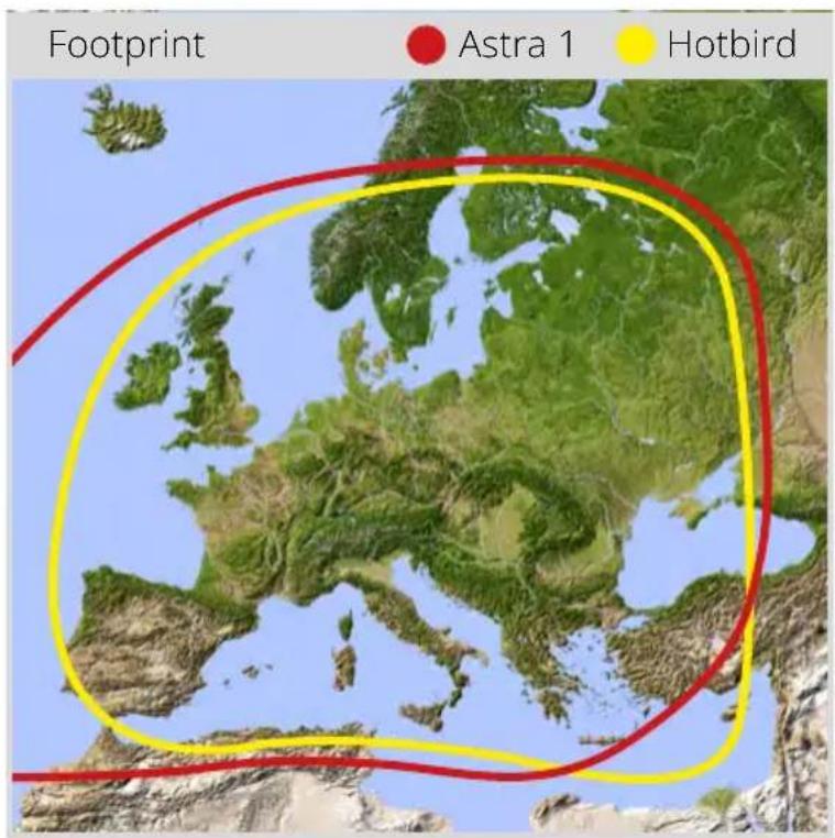
text_image
Footprint Astra 1 HotbirdCaravanman 85
text_image
Footprint Astra 1 HotbirdNote: In the peripheral areas of the footprint reception interference may occur.
7. Control via the App
7.1 Installing the App on the Mobile Device

text_image
MEGASATFirst you have to download the app. You can find it in the AppStore and Google PlayStore under the following name:
Megasat 65/85 V2
7.2 Connection to the control unit
The first time you use it, you must pair the control device with the mobile device. Note: This is only necessary for the first use!
- Open the Megasat app.
- To activate pairing mode, press and hold the standby key (⏻) on the front of the control unit until a signal tone is heard.
- Wait until your mobile device detects the control device.
Note: Make sure that you have activated Bluetooth® on your mobile device and that you are only max. 5 metres away from the control device! - When the pairing process is complete, a message appears on the mobile device.
- If the connection is not established automatically, press the Ⓐ-button in the app.
7. Control via the App
7.3 Declaration of the App
text_image
Megasat 65/85 V2 MEGASAT Verbunden Update ASTRA 19E HOTBIRD 13E ASTRA 28E ASTRA 23E EUTELSAT 9E THOR 1W Status: Standby
- Changes the selected satellite (up / down).
- Opens or closes the antenna.
- Opens the "Configuration" page.
- Updates the satellite configurations (firmware update) if available.
- Displays the satellite parameters.
- Open the manual setting menu.
- Synchronization with the control unit. If the control panel is connected or disconnected to the control unit, synchronization is required to detect hardware changes. Synchronization is also necessary to obtain configuration changes made via USB.
- Displays the device information.
7. Control via the App
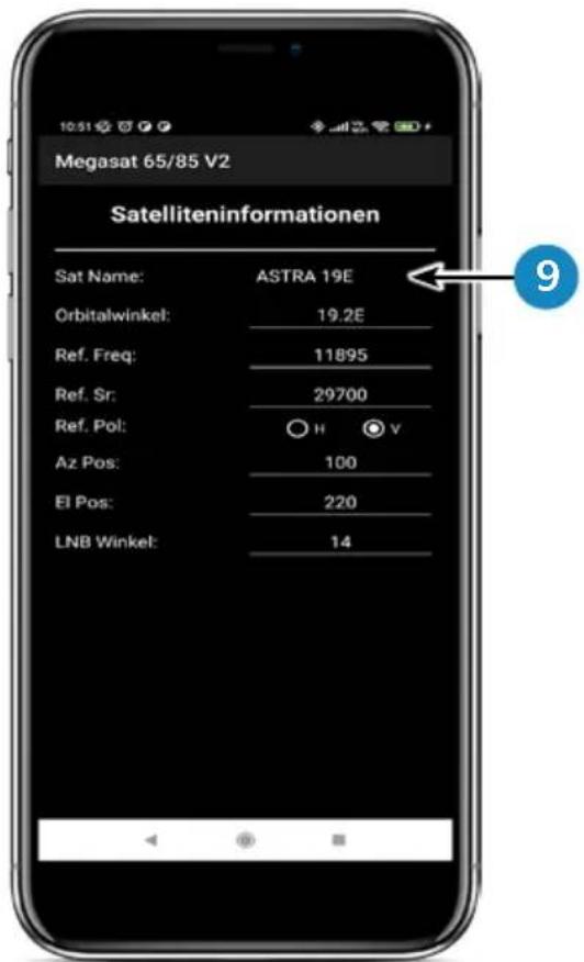
text_image
Megasat 65/85 V2 Satelliteninformationen Sat Name: ASTRA 19E Orbitalwinkel: 19.2E Ref. Freq: 11895 Ref. Sr: 29700 Ref. Pol: H V Az Pos: 100 El Pos: 220 LNB Winkel: 14- Select the satellite by pressing the satellite name. The satellite information is then listed below.
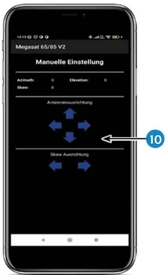
- In the „Manual Adjustment“ menu, rotate the antenna with the left and right arrows for azimuth, or rotate the antenna with the up and down arrows for elevation.
7. Control via the App
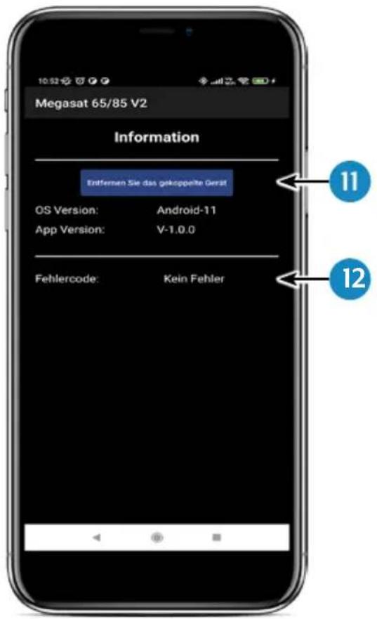
-
If you want to separate the app with the control device, press this field. You can then pair with another or new control device.
-
If an error occurs during operation with the system, an error code is displayed here.
8. Troubleshooting
During normal operation, the LEDs on the control panel indicate which satellite is currently selected. But in case of an error they have a special meaning, as described below.
The control panel has several indicators to show messages about unexpected or faulty conditions. Each message is indicated by an alarm signal from the keypad and the LEDs are highlighted:
Error 1 (LED 1):
Height sensor error when opening.
Check the control cable on the control unit side and on the antenna side.
Error 2 (LED 2):
Height sensor error when closing. Check the control cable on the control unit side and on the antenna side.
Error 3 (LED 1 + LED 2):
The antenna cannot reach the azimuth switches at the desired time. Check if the antenna encounters an obstacle that restricts the movement of the antenna.
Error 4 (LED 3):
During operation when the azimuth closing side switch is interrupted (at 0 degrees). Check the control cable on the control unit side and on the antenna side.
Error 5 (LED 1 + LED 3):
During operation when the azimuth return switch (at 360 degrees) is interrupted. Check the control cable on the control unit side and on the antenna side.
Error 6 (LED 2 + LED 3):
During operation, when the connection to the front switch is interrupted (at 0 degrees). Check the control cable on the control unit side and on the antenna side.
Error 7 (LED 1 + LED 2 + LED 3):
During operation, when the connection to the rear side switch is broken (at 180 degrees) OR when the control cable is not connected. Check that the control cable is connected. (Check that it is connected to the control unit)
Error 8 (LED 4):
The LNB or LNB cable is not connected or one of them is damaged. Check that the LNB cable is connected to the control unit side and the LNB side.
8. Troubleshooting
Error 9 (LED 1 + LED 4):
Smartsearch antenna board, sensor board or GPS card is not connected or damaged. Check that the control cable is connected. Also check the internal pins on the control cable side and the control unit side for damage.
Error 10 (LED 2 + LED 4):
Failure of the azimuth motor encoder. Check the control cable on the control unit side and on the antenna side.
Error 11 (LED 1 + LED 2 + LED 4):
Azimuth overcurrent failure. Check that the antenna does not encounter an obstacle that will prevent the antenna from moving.
Error 12 (LED 3 + LED 4):
Elevation overcurrent failure failure. Check if the antenna encounters an obstacle that restricts the movement of the antenna.
Error 20:
The antenna can't find the satellite. Check whether a newer firmware is available for the antenna (transponder update). A current firmware can be found on the homepage „www.megasat.tv“. Check whether a building, a tree or other obstructions reduce or block reception.
9. Firmware-Update
From time to time it may be necessary to update the firmware of the control unit (e.g. in case of a frequency change of the satellite operator or a general improvement of the control unit).
The current firmware can be found on our homepage www.megasat.tv
9.1 Update via USB device
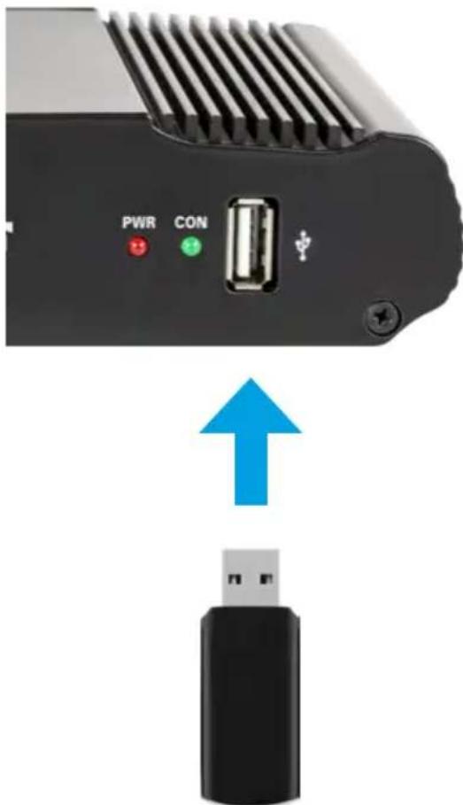
text_image
PWR CON ↑- Copy the firmware file to a suitable USB stick. The USB stick should be formatted to FAT32 and should not contain any other files.
- Make sure that the control unit is turned off at the main switch.
- Insert the USB stick with the new firmware into the USB port on the front panel.
- Now switch on the control unit. The control unit boots and starts the update process automatically. IMPORTANT: Do not switch off the control unit during the update process to avoid possible damage!
- After a successful update, the control unit switches off and restarts automatically. The update process is now finished.
9.2 Update via Smartphone or Tablet
When frequency changes are made by the satellite operators, the app will be updated automatically. A notice will appear in the app that you should update the antenna.
Make sure you have Bluetooth® enabled on the mobile device and the antenna is connected to the mobile device.
Then follow the instructions in the app.
10. Specifications
| Caravanman 65 Premium V2 | Caravanman 85 Premium V2 | |
| Number of subscribers 1 | ||
| Satellite input frequency 10.7 | ~ 12.75 GHz | |
| Polarization Vertical / Horizontal | ||
| Frequency band Ku-Band | ||
| Frequency range 10,7 GHz – 12,75 GHz | ||
| Antenna gain 35,1 dBi @ 11,8 GHz | 36,8 dBi @ 11,8 GHz | |
| Receive power 45 dBW 43,5 dBW | ||
| Motor 2 axis DC-motor | ||
| Angular range rotation 360° | (20° per second) | |
| Angular range inclination: | 0° ~ 75° (10° per second) | |
| Programmed satellites | Astra 1 (19,2° East)Astra 2 (28,2° East)Astra 3 (23,5° East),Hotbird (13° East)Thor (0,8° West)Eutelsat 9 B (9° East) | |
| Input voltage | DC 12 ~ 24 Volt, 10 A | |
| Operating temperature: | -15°C ~ +50°C | |
| Storage temperature | -30°C ~ +70°C | |
| Mirror size | 66,0 x 71,0 cm (W/H) | 77,0 x 85,0 cm (W/H) |
| Antenna dimensions (retracted) | 66,0 x 20,0 x 87,0 cm (W/H/L) | 77,0 x 20,0 x 100,0 cm (W/H/L) |
| Weight antenna 12.1 kg | 13,3 kg | |
| Dimensions control unit | 18,0 x 4,0 x 13,0 mm (W/H/D) | |
Note 1:
Weight and dimensions are not the absolute exact values. Specifications are subject to change without notice.
Note 2:
The antennas Caravanman 65 / 85 Professional V2 also offer a GPS receiver, automatic skew function and connections for 2 participants.
11. Dimensions
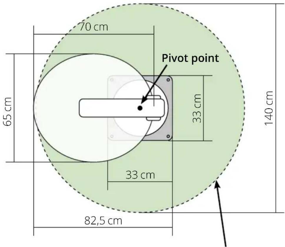
11.1 Caravanman 65 V2
text_image
70 cm Pivot point 65 cm 33 cm 140 cm 33 cm 82,5 cmmax. Swivel range
11. Dimensions
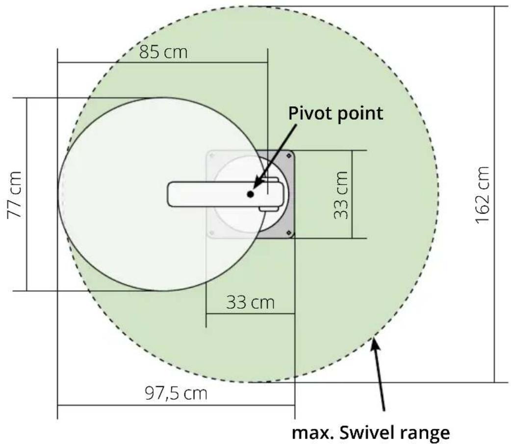
11.2 Caravanman 85 V2
text_image
85 cm 77 cm 33 cm 33 cm 162 cm 97,5 cm Pivot point max. Swivel rangeConformity information
Megasat Werke GmbH hereby declares that the following equipment is in compliance with the essential requirements and other relevant provisions of Directives 2014/30/EU (EMC), 2014/35/EU (LVD) and 2014/53/EU (RED):
Caravanman 65 Premium V2 (Art-No. 1500197)
Caravanman 65 Professional GPS V2 (Art-No. 1500198)
Caravanman 85 Premium V2 (Art-No. 1500199)
Caravanman 85 Professional GPS V2 (Art-No. 1500200)
The declaration of conformity for this product is available to the company:
You can download the declaration of conformity on our homepage:
www.megasat.tv/support/downloads
Notes
H11026-04
Version: 1.2 (January 2023) // Technical changes, misprints and errors reserved.
natural_image
White satellite dish with 'MEGASAT' branding on its side, mounted on a base (no additional text or symbols visible)Caravanman 65 / 85 Premium V2 Caravanman 65 / 85 Professional GPS V2
natural_image
Purple cloth cleaning a white surface with a blue hand partially visible (no text or symbols)natural_image
Close-up of a white mechanical device with a pencil inserted, placed on a flat surface with dashed lines indicating alignment (no text or symbols visible)natural_image
Pure diagram of a U-shaped pipe or tube inside a dashed diamond shape on a white surface (no text or symbols)natural_image
Close-up of a white plastic electrical plug with two metallic connectors (no text or symbols visible)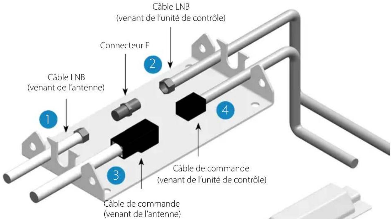
natural_image
Mechanical assembly diagram showing a component being inserted into a housing, with a red arrow indicating the process (no text or symbols present)natural_image
Abstract geometric diagram with intersecting gray and red lines (no text or symbols)pauvre Réception

natural_image
Abstract geometric shape with intersecting red and blue lines forming a cross (no text or symbols)bon Réception

natural_image
Simple cross-shaped diagram with red vertical line crossing blue horizontal line (no text or symbols)meilleur Réception
text_image
Position du LNB Signal satellitenatural_image
3D model of a device showing internal components before and after assembly, with blue arrows indicating direction (no text or symbols)natural_image
Close-up of a black electronic device with ventilation grille, ports labeled PWR and CON, and a USB port (no readable text beyond labels)
natural_image
Black USB flash drive with a blue upward arrow above it (no text or symbols)www.megasat.tv/support/downloads
Notes
H11026-04