
ELVOX ZR02 - Detector Vimar - Free user manual and instructions
Find the device manual for free ELVOX ZR02 Vimar in PDF.

| Product type | Double induction loop controller |
| Brand | Vimar |
| Model | ELVOX ZR02 |
| Power supply | 12-24 V AC/DC ±10% |
| Power consumption | < 2.5 W |
| Weight | < 200 g |
| Protection degree | IP40 |
| Number of loops | 2 (double) |
| Outputs | 2 changeover relays (potential-free) |
| Max. relay contact voltage | 230 Vac |
| Max. relay contact current | 5 A (resistive) |
| Oscillation frequency | 20 - 130 kHz |
| Sensitivity (ΔL/L) | 0.005% to 0.5% in 250 steps |
| Reaction time | 25 ms (single loop), 50 ms (double) |
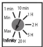
| Presence time | 1 min to infinite (250 steps) |
| Pulse duration | 100 ms or 500 ms |
| Compliance | EMC 2004/108/EC, UL 508 |
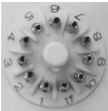
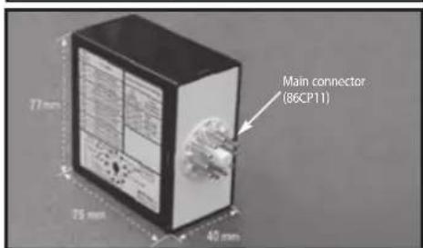
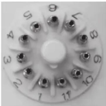
| Connector | 11-pin type 86CP11 |
| LED indicators | 1 green (power), 2 red (loop status) |
| Protections | Isolation transformer, Zener diodes, gas discharge tube |
| Maintenance | Disconnect the device before any cleaning or maintenance operation |
| Safety | Installation according to standards; use an omnipolar switch with contact separation ≥ 3 mm |
Frequently Asked Questions - ELVOX ZR02 Vimar
User questions about ELVOX ZR02 Vimar
0 question about this device. Answer the ones you know or ask your own.
Ask a new question about this device
Download the instructions for your Detector in PDF format for free! Find your manual ELVOX ZR02 - Vimar and take your electronic device back in hand. On this page are published all the documents necessary for the use of your device. ELVOX ZR02 by Vimar.
USER MANUAL ELVOX ZR02 Vimar
Digital inductive loop sensors
Spinotto 6:Rele A (COM)
Spinotto 7: Spira A ZR01
Spinotto 11: Relè B (NC)
REGOLAZIONI
A. 3 CONFIGURAZIONI
The ZR Digital Inductive Loop Detector range is the ideal solution for parking barrier control, motorized gates and doors, vehicle access control and industrial control systems.
The ZR range is a high performance single or dual channel vehicle detector packaged in a compact housing, the connection is made with an industrial standard 11-pin round connector.
Six versions listed below are available, single or dual channel, and 3 possibilities for the power supply :
ZR0/110: Single loop detector with 110 to 120 Vac power supply
ZR01/220: Single loop detector with 220 to 240 Vac power supply
ZR01: Single loop detector with 12 to 24 Vac/dc power supply
ZR02/110: Dual loop detector with 110 to 120 Vac power supply
ZR02/220: Dual loop detector with 220 to 240 Vac power supply
ZR02: Dual loop detector with 12 to 24 Vac/dc power supply
SPECIFICHE TECNICHE
Technology inductive loop
Tuning automatic
Detection mode presence
Presence time 1 min to infinity (permanent)
presence) with 250 steps
Pulse time output 100 ms or 500 ms
Inductance range 20 H to 1000 H
Frequency range 20 kHz to 130 kHz
Frequency steps 4 for single loop
2 for dual loop (for each loop)
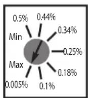
Sensitivity ( L / L) 0.005% to 0.5% with 250 steps
Reaction time 25 ms for single loop
50 ms for dual loop (each channel)
Power supply (depending on model) 12-24 ac/dc ±10%
230 Vac ±10%
90---->125Vac±0%
Mains Frequency 48 to 62 Hz
Power Consumption <2.5W
Storage temperature range -30°C to +70°C
Operating temperature range -30^ to +40^
Degree of protection IP40
2 Output relays
(free potential change-over contact)
UL listed equipment for UL 508
DESCRIPTION OF THE SENSOR
LOOPS INSTALLATION TIPS
A. CABLE SPECIFICATIONS FOR LOOP AND FEEDER
1.5mm² cross section area
Multi-strand cable
Insulation material : PVC or Silicone
- For the feeder cable, the wire must be twisted at least 15 times by meter
- Feeder for long runs used for foil screened cable is recommended (earth at equipment end only)
- The feeder cable must be firmly fixed to avoid any false detection (max length : 100 m)
- Waterproof cable junction box is required
B. LOOP GEOMETRY
- With two adjacent loops connected to a dual channel sensor, it is possible for these loops to share a common slot, if so required. As the channels are multiplexed, no interference will occur
- Avoid large loops or long feeder (max 100 m), the sensitivity will be affected
| Frequency adjustment for loop A for single loop detector | ||
| Dip Switch #1 | Dip Switch #2 | Loop frequency |
| OFF | OFF | High |
| ON | OFF | Mid High [High -20%] |
| OFF | ON | Mid Low [High - 25%] |
| ON | ON | Low [High - 30%] |
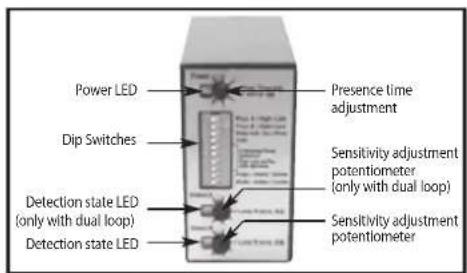
LED SIGNAL
- 1 Green LED shows when the module is powered
2 Red LEDs give
the corresponding loop detection state in normal situation
- the value of the oscillation frequency measurement or an error message on power ON
In normal situation the red LED stays ON as long as the loop detects any metallic object.
On power ON the sensor measures the oscillation frequency of each loop. The result of this measurement is displayed using
the corresponding red LED. The amount of blinking indicates the tens value of the frequency. For example 4 short flashes correspond to a frequency between 40kHz and 49kHz . After this message the LED goes back to normal display.
If the loop oscillation frequency falls outside the limits set between 20kHz and 130kHz the red LED displays an error
message and the sensor activates the corresponding relay. The blinking frequency shows the type of error according to the
next table. The sensor will stay in this state until the problem is cleared and the frequency goes to the right range.
Remark : The sensor launches automatically a learning process if the oscillation frequency changes more than 10% in
comparison with the measurement value.
| Loop frequency error LED d | splay |
| Oscillation frequency too LOW or loop open | LED blinking at 1Hz |
| Oscillation frequency too HIGH LED blinding faster at 2 Hz | blinking faster at 2 Hz |
| Loop shorted or no oscillation LED blinding slower at 0.5 Hz | blinding slower at 0.5 Hz |
TROUBLESHOOTINGS
| SYMPTOM PROBABLE CAUSE CORRECT ACTION | ||
| The loop detector will not workThe green LED is off | There is no power supply to the loop detector | Check power supply |
| The loop detector will not workThe red LED is flashing slowly (0.5 Hz) | The corresponding loop is shorted | Check the loop cable |
| The loop detector will not workThe red LED blinks at either 1Hz or 2Hz | The frequency of oscillation falls outside the allowed range | Adjust frequency with dip switches or change loop turns |
| The loop LED is detecting properly but the contact is not made | Bad connection of the relay contacts | Check relay connections |
| Dip switches 5 to 8 are not responding properly | Their function varies according to dip switch #10 setting | Check the appropriate loop mode required and adjust dip switch #10 |
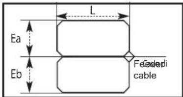
C. DETERMINATION OF THE NUMBER OF LOOP TURNS
WARNING:
For conformity reasons, in any situation, the antenna factor defined as the loop surface multiplied by the number of turns should not exceed NA = 20
For example, if L = 2m , Ea = 1m and the number of turns = 4 , then the NA = 2 × 1 × 4 = 8 < 20 .
Find hereafter the recommended values for the turns :
| Area Number of turns | |
| < 3 m2 | 4 |
| 3 - 5 m2 | 3 |
| 6 - 10 m2 | 2 |
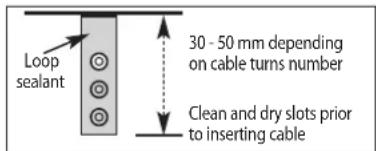
D.SLOT DEPTH
WIRING
WARNING: Do not remove the grease on the connector's pins
UL REQUIREMENT: The unit has to be mounted on a suitable UL recognized SWIV2 Relay Socket
Pin 1: Power supply
Pin 2:Power Supply
Pin 3:Relay B (NO)
Pin 4:Relay B (COM)
Pin 5:Relay A (NO)
Pin 6:Relay A (COM)
Pin 7: Loop A (ZR01)
Pin 8: Loop common and earth
Pin 9: Loop B (ZR02)
Pin 10:Relay A (NC)
Pin 11:Relay B (NC)
ADJUSTMENT
A. THE 3 CONFIGURATIONS
- Configuration # 1: single loop detector (ZR01)
- Configuration # 2: dual loop detector in independent mode (ZR02 with dip switch #10 OFF)
- Configuration # 3: dual loop detector in combined mode (ZR02 with dip switch #10 ON)
B. POTENTIOMETERS
PRESENCE TIME
SENSITIVITY
- A potentiometer for adjustment of the maximum duration of a presence detection: from 1 min to infinity
A potentiometer for adjustment of the linear sensitivity (Af) for the loop A: from 0.005% to 0.5%
A potentiometer for adjustment of the linear sensitivity (Af) for the loop B: from 0.005% to 0.5%
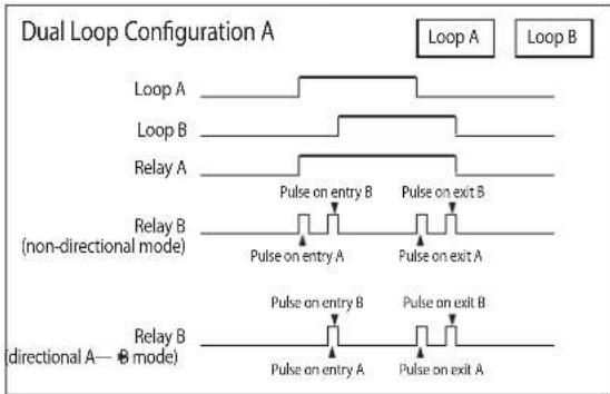
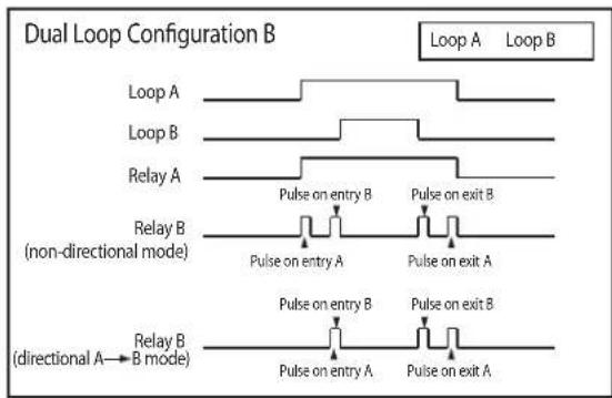
C. RELAY CONFIGURATIONS (Dip Switch #3)
The loop A activates the relay A and the loop B activates the relay B. With the dual loops in combined mode the relay A provides the presence detection and the relay B provides the movement direction
| ACTIVE MODE (dip switch #3 OFF) | PASSIVE MODE (dip switch #3 OFF) | |
| Detection | COM NO NC | COM NO NC |
| No Detection | COM NO NC | COM NO NC |
D. DIP SWITCHES
After each dip switch change the sensor launches a learning process
| Dip-switch #1 Frequency Adjustments of Loop A |
| Dip-switch #2 Frequency Adjustments of Loop A (with single loop) or Loop B (with dual loops) |
| Dip-switch #3 Relay configuration: active or passive. |
| Dip-switch #4 Automatic Sensitivity Boost (ASB option) [recommended for better trucks detection] :During a detection the sensitivity increases automatically to 8 times the preset sensitivity given by the sensitivity potentiometer adjustment.It is limited to the maximum sensitivity (Af = 0.005%).It goes back to the preset value after detection stops. |
| Dip-switch #5 Relay A function: presence or pulse (not used with dual loop in combined mode) |
| Dip-switch #6 Relay A Pulse type: entry or exit (used only at pulse function)or Relay B mode (with dual loop in combined mode) (see next drawing)·non-directional :The relay B provides a pulse according to the dip switches #7 and #8 setting.The relay B provides a pulse only if the loop A is detecting before the Loop B.The detection takes place according to dip switches #7 and #8 logic.Warning : During the detection, the 2 loops have to detect simultaneously for a short period to be able to determine the movement direction.During loop installation make sure the 2 loops are close enough to each other to ensure a common detection (typical 1m). |
| Dip-switch #7 Relay B function: presence or pulse or loop selection for relay B pulse : pulse on Loop B or pulse on Loop A (used with dual loop in combined mode) |
| Dip-switch #8 Relay B Pulse type: entry or exit (used only at pulse function) |
| Dip-switch #9 Pulse duration for both relays (used only at pulse function): 100 ms or 500 ms |
| Dip-switch #10 Dual loop mode: independent or combined A-B (not used with single loop) |
| Configuration #1 Single loop | Configuration #2 Dual loop in independent mode | Configuration #3 Dual loop in combined mode | ||||
| OFF ON OFF ON ON | ||||||
| DS#1 | See next table High (loop B) Low (loop B) | High (loop A) Low (loop A) [High -30%] | High (loop A) Low (loop A) [High -30%] | |||
| DS#2 High | [High -30%] | High (loop B) Low (loop B) [High -30%] | ||||
| DS#3 | Active mode | Passive mode | Active mode | Passive mode | Active mode | Passive mode |
| DS#4 ASB OFF ASB ON ASB OFF ASB ON | ||||||
| DS#5 Relay A : Presence on loop A | Relay A : Pulse on loop A | Relay A : Presence on loop A | Relay A : Pulse on loop A | Relay A : Pulse on loop A | Not used Not used | |
| DS#6 Relay A : Pulse on loop A entry | Relay A : Pulse on loop A exit | Relay A : Pulse on loop A entry | Relay A : Pulse on loop A exit | Relay A : Pulse on loop A non-directional mode | Relay B : directional A—B mode | |
| DS#7 Relay B : Presence on loop A | Relay B : Pulse on loop A | Relay B : Presence on loop B | Relay B : Pulse on loop B | Relle B : Impulso sulla spira B | Relle B : Impulso sulla spira A | |
| DS#8 Relay B : Pulse on loop A entry | Relay B : Pulse on loop A exit | Relay B : Pulse on loop B entry | Relay B : Pulse on loop B exit | Relay B : Pulse on loop entry | Relay B : Pulse on loop exit | |
| DS#9 | 100 ms | 500 ms | 100 ms | 500 ms | 100 ms | 500 ms |
| DS#10 | Not used | Not used | Independent mode | Combined mode | Independent mode | Combined mode |
ANWENDUNGEN
Stift 7: Schleife A (ZR01)
FONCTIONNEMENTS INCORRECTS
77mm (A) x 40 mm (L) x 75 mm (P)
Dimensoes
<200g
Peso
R&TTE 1999/5/EC EMC 2004/108/EC
Conformidade
- Carefully read the instructions on this leaflet: they give important information on the safety, use and maintenance of the installation.
- After removing the packing, check the integrity of the set. Packing components (plastic bags, expanded polystyrene etc.) are dangerous for children. Installation must be carried out according to national safety regulations.
It is convenient to fit close to the supply voltage source a proper omnipolar type switch with 3mm separation (minimum) between contacts. - Before connecting the set, ensure that the data on the label correspond to those of the mains.
- Use this set only for the purposes designed, i.e. for electric door opener systems. Any other use may be dangerous. The manufacturer is not responsible for damage caused by improper, erroneous or irrational use.
- Before cleaning or maintenance, disconnect the set.
- In case of failure or faulty operation, disconnect the set and do not open it.
- For repairs apply only to the technical assistance centre authorized by the manufacturer.
- Safety may be compromised if these instructions are disregarded.
- Do not obstruct opening of ventilation or heat exit slots and do not expose the set to dripping or sprinkling of water.
- Installers must ensure that manuals with the above instructions are left on connected units after installation, for users' information.
- All items must only be used for the purposes designed.
- WARNING: to avoid the possibility of hurting yourself, this unit must be fixed to the wall according to the installation instructions.
- This leaflet must always be enclosed with the equipment.

Directive 2002/96/EC (WEEE)
The crossed-out wheelie bin symbol marked on the product indicates that at the end of its useful life, the product must be handled separately from household refuse and must therefore be
assigned to a differentiated collection centre for electrical and electronic equipment or returned to the dealer upon purchase of a new, equivalent item of equipment.
The user is responsible for assigning the equipment, at the end of its life, to the appropriate collection facilities. Suitable differentiated collection, for the purpose of subsequent recycling of decommissioned equipment and environmentally compatible treatment and disposal, helps prevent potential negative effects on health and the environment and promotes the recycling of the materials of which the product is made. For further details regarding the collection systems available, contact your local waste disposal service or the shop from which the equipment was purchased.
Risks connected to substances considered as dangerous (WEEE).
According to the WEEE Directive, substances since long usually used on electric and electronic appliances are considered dangerous for people and the environment. The adequate differentiated collection for the subsequent dispatch of the appliance for the recycling, treatment and dismantling (compatible with the environment) help to avoid possible negative effects on the environment and health and promote the recycling of material with which the product is compound.

Product is according to EC Directive 2004/108/EC and following norms.
CONSEILS POUR L'INSTALLATEUR
Directive 2002/96/CE (WEEE, RAEE)
- REGOLAZIONI
- 3 CONFIGURAZIONI
- SPECIFICHE TECNICHE
- LOOPS INSTALLATION TIPS
- CABLE SPECIFICATIONS FOR LOOP AND FEEDER
- LED SIGNAL
- DETERMINATION OF THE NUMBER OF LOOP TURNS
- WARNING:
- D.SLOT DEPTH
- WIRING
- ADJUSTMENT
- THE 3 CONFIGURATIONS
- POTENTIOMETERS
- PRESENCE TIME
- RELAY CONFIGURATIONS (Dip Switch #3)
- DIP SWITCHES
- ANWENDUNGEN
- Directive 2002/96/EC (WEEE)
- Risks connected to substances considered as dangerous (WEEE).
- CONSEILS POUR L'INSTALLATEUR
- Directive 2002/96/CE (WEEE, RAEE)
Brand : Vimar
Model : ELVOX ZR02
Category : Detector