7835 - Measuring equipment SOEHNLE - Free user manual and instructions
Find the device manual for free 7835 SOEHNLE in PDF.
| Product type | Medical column scale |
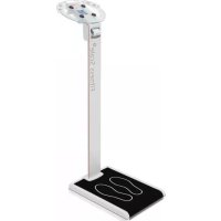
| Available models | 7835.01 (column scale), 7835.02 (column scale with stadiometer) |
| Capacity | 200 kg or 300 kg depending on version |
| Graduation | 100 g |
| Minimum load | 2 kg (200 kg model) / 1 kg (300 kg model) |
| Dimensions (L x D x H) | 7835.01 : 362 x 488 x 990 mm ; 7835.02 : 362 x 488 x 1310 mm |
| Weight | Approx. 15 kg (estimate) |
| Display | LCD 6 digits, backlit, digit height 20 mm |
| Power supply | 6 AA LR6 batteries (supplied) or optional mains adapter (ref. 2557.05.002) |
| Main functions | Weighing, zeroing, manual and pre-tare, unit change (kg/lb, cm/ft), Hold function, BMI calculation, child weighing, integrated stadiometer (model 7835.02) |
| Intended use | Determining the weight of persons in professional environments (medical, care) |
| Housing material | ASA |
| Protection class | IP20 |
| Operating temperature | +5°C to +35°C |
| Storage temperature | -10°C to +55°C |
| Permissible humidity | 20% to 85% (non-condensing) |
| Cleaning | Disconnect before cleaning; use a soft cloth and common household cleaners; avoid liquids entering the device |
| Approved disinfection | Denatured alcohol, isopropanol, Kohrsolin 2%, Sokrena 1%, Sagrotan 5%, Gigasept 5% |
| Maintenance | Periodic verification with a known weight; repair only by a Soehnle authorized service center |
| Warranty | 24 months from date of purchase |
| Optional accessories | Mains power adapter (ref. 2557.05.002), RS232 interface |
| Approval | Available for models 7835.01.001, 7835.01.002, 7835.02.001, 7835.02.002 |
Frequently Asked Questions - 7835 SOEHNLE
User questions about 7835 SOEHNLE
0 question about this device. Answer the ones you know or ask your own.
Ask a new question about this device
Download the instructions for your Measuring equipment in PDF format for free! Find your manual 7835 - SOEHNLE and take your electronic device back in hand. On this page are published all the documents necessary for the use of your device. 7835 by SOEHNLE.
USER MANUAL 7835 SOEHNLE
https://www.soehnle-professional.com/site/documents
5.1 Intended use 36
5.2 Security advice 36
5.3 Cleaning 37
5.4 Disinfection 37
5.5 Sterilisation 37
5.6 Maintenance and service 37
5.7 Guarantee/Warranty/Liability 38
5.8 Disposal of batteries and accumulators 38
5.9 Disposal of the scale 38
- Labelling 39
6.1 CE Marking 39
6.2 Marking on the type plate 39
- Product description 40
7.1 Connection and device description 40
7.2 Operating buttons 40
7.3 Display symbols 41
- Assmeebly 42
8.1 Installation note 42
8.2 Installation steps 42
- Commissioning. 46
9.1 Installation note 46
9.2 Power supply 46
- Operation 47
10.1 Switch on 47
10.2 Weighing 47
10.3 Zeroing 47
10.4 Taring 47
10.5 Switching units 48
10.6 Hold function 49
10.7 BMI function 49
10.8 Small child weighing 50
10.9 Operation of the length measuring rod 50
10.10 Switch off / End operation safely.. 51
- Malfunctions - causes and elimination 52
- Notes on electromagnetic compatibility 53
Thank you for choosing this product from Soehnle Industrial Solutions.
It is equipped with all the features of the latest technology and has been optimised for easy operation.
Please read the instructions for use carefully before using the product.
If you have any questions or if problems occur with your device that are not covered in the instructions for use, please contact your Soehnle Industrial Solutions service centre or our customer advisory service:
Telefon: +49 7191 3453-220
Fax: +49 7191 3453-211
These operating instructions describe all the standard functions and settings of Soehnle Professional stand scale 7835. Deviations are possible for special designs.
Available versions:
7835.01.001/7835.01.002 Stand scale
7835.02.001 / 7835.02.002 Stand scale with height rod
Further information and documentation can be found at https://www.soehnle-professional.com/site/documents
Please go to the Customer Centre on our website www.soehnle-professional.com and select the Stand scale 7835 under Downloads / Technical Documents / Medical Scales / Personal Scales or Personal Scales with Stand.
2. Scope of delivery
| Scope of delivery: 7835.01.00x 7835.02.00x | ||
| Personal Scale 7835 | ✓ | ✓ |
| Instructions for use | ✓ | ✓ |
| 6x AA-Batteries LR6 | ✓ | ✓ |
| Stand tube with display unit | ✓ | ✓ |
| Screw set stand tube | ✓ | ✓ |
| Length measuring rod | × | ✓ |
| Holder for length measuring rod (2x) | × | ✓ |
| Fixing screws for holder(4 x pan-head screw M4x10) | × | ✓ |
| Fixing screws for length measuring rod(2 x countersunk screw M5x8) | × | ✓ |
Optionally available:
In case of a malfunction, please contact Soehnle Industrial Solutions' customer service by phone +49 7191 / 3453 320 or e-mail service@sis.gmbh. Unauthorised modifications or repairs may damage the scale and void the manufacturer's warranty.
Disconnect the power supply to this balance before any installation, cleaning or maintenance.
Do not expose the scale to direct sunlight. This could lead to colour changes.
If the scale is not to be used for a long period of time, remove the batteries or the power cord.
- Avoid stacking materials on the scale and the display unit or loading the scale with more than the maximum load allowed. This can cause damage.
- Place the scale on a firm, stable and level surface so that accurate measurement results can be guaranteed. Measurement results obtained on a soft or inclined surface are not allowed on conformity assessed scales.
Do not connect the scale to unstable voltage sources.
Simultaneous contact between the interface and the patient is not permitted.
Use only the original accessories. Use of other brands may cause damage to the scale.
Read the user manual

4.1 Versions
4.1.1 Stand scale 7835.01
| Stand scale 7835.01.001 7835.01 | .002 | |
| Maximum load: 200 kg 300 kg | ||
| Division: | 100 g 100 g | |
| Minimum load: | 2 kg 1 kg | |
| Approvable: | x | x |
| Display: | 7-Segment, 6-digit LCD, backlit | |
| Digit height: 20 mm | ||
| Material of the housing: ASA | ||
| Protection class: IP20 | ||
| Dimensions (WxDxH): | 362 x 488 x 990 mm | |
| Power supply: | 6 x AA Batteries or power supply 100 - 240 V AC (Art. Nr. 2557.05.002) or AA size batteries can be used - the charge level indicator may show too low a value. If the scale is to be operated with rechargeable batteries over a long period, battery operation can be activated in the scale. (see chapter 9.2) | |
| Working temperature: | + 5°C to + 35°C | |
| Storage temperature: | - 10°C to + 55°C | |
| Moisture: | 20% to 85% (non-condensing) | |
| Air pressure: | 900 bis 1.050 hPa | |
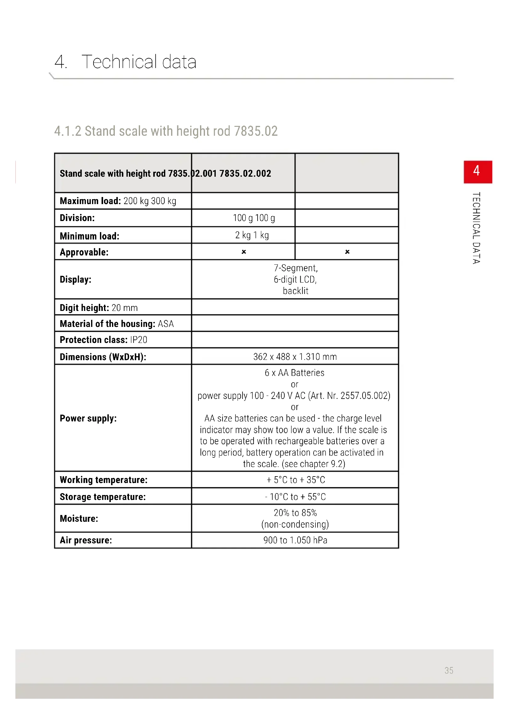
4.1.2 Stand scale with height rod 7835.02
| Stand scale with height rod 7835. | 02.001 7835.02.002 | |
| Maximum load: 200 kg 300 kg | ||
| Division: | 100 g 100 g | |
| Minimum load: | 2 kg 1 kg | |
| Approvable: | × | × |
| Display: | 7-Segment, 6-digit LCD, backlit | |
| Digit height: 20 mm | ||
| Material of the housing: ASA | ||
| Protection class: IP20 | ||
| Dimensions (WxDxH): | 362 x 488 x 1.310 mm | |
| Power supply: | 6 x AA Batteries or power supply 100 - 240 V AC (Art. Nr. 2557.05.002) or AA size batteries can be used - the charge level indicator may show too low a value. If the scale is to be operated with rechargeable batteries over a long period, battery operation can be activated in the scale. (see chapter 9.2) | |
| Working temperature: | + 5°C to + 35°C | |
| Storage temperature: | - 10°C to + 55°C | |
| Moisture: | 20% to 85% (non-condensing) | |
| Air pressure: | 900 to 1.050 hPa | |
5. General Information
5.1 Intended use
The 7835 stand scales are used to determine the weight of persons.
The device measures the weight force on the weighing platform and transmits it electronically to the display.
The device does not provide interpretable results, it provides weight values. It is the responsibility of qualified personnel to assess the weights.
5.2 Security advice
This scale is designed for professional use.
The user must be familiar with the operation of the scale.
Please read the information in the instruction for use carefully before use. They contain important instructions for the installation, proper use and maintenance of the appliance. The manufacturer is not liable if the following instructions are not observed. The warranty is void if the unit is not installed correctly. If electrical components are used under increased safety requirements, the relevant regulations must be observed.
The stand scale 7835 must not be used in hazardous areas.
The permissible mains voltage is 100 - 240 volts. Electrical connection conditions must correspond to the values printed on the type plate.
If the optionally available power supply unit is damaged, the scale must not be operated any further with this power supply unit, disconnect the power supply and call a Soehnle Industrial Solutions service centre. However, battery operation is still possible.
This device is radio interference suppressed in accordance with the applicable EC Directive 2014/30/EU. However, under extreme electrostatic and electromagnetic influences, e.g. when operating a radio or mobile phone in the immediate vicinity of the device, the display value may be affected. After the interference has ceased, the product can be used again according to its intended purpose; if necessary, it must be switched on again. In case of permanent electrostatic interference, please contact the responsible Soehnle Industrial Solutions service partner.
The device is a measuring instrument. Drafts, vibrations, rapid temperature changes and sunlight can affect the weighing result.
5. General Information
5.3 Cleaning
Always disconnect the scale from the power supply before cleaning.
Clean the scale as required using normal household cleaning agents. Ensure that no liquid enters the scale. Wipe with a dry, soft cloth.
Never use abrasive or aggressive cleaning agents for cleaning. These agents can damage the scale.
5.4 Disinfection
The 7835 personal scales may be disinfected with the following agents:
Denatured alcohol
Isopropyl (alcohol)
2% kohrsoline
1% aqueous solution of Socrena
5% Sagrotan
5% Gigasept
The specific instructions for use must be observed.
5.5 Sterilisation
The 7835 stand scales must not be subjected to any sterilisation process.
5.6 Maintenance and service
The scale must be regularly subjected to a preventive inspection. To do this, load the scale with a known weight and compare the value of the terminal with the test weight. In case of deviations, maintenance or adjustment must be carried out.
The scale may only be opened and repaired by trained service personnel authorised by Soehnle Industrial Solutions. If the scale does not work as intended, damage is suspected. In this case, the scale must be taken to a service station authorised by Soehnle Industrial Solutions. In case of repair by an authorised service station, only original spare parts may be used.
5. General Information
5.7 Guarantee / Warranty / Liability
If there is a defect in the delivered item for which the manufacturer is responsible, the manufacturer is entitled to choose between either eliminating the defect or delivering a replacement. Replaced parts become the property of the manufacturer. If the remedy of the defect or replacement fails, the statutory provisions shall apply.
The warranty period is 24 months and begins on the day of the first purchase of the product. Please keep the invoice as proof. In case of service please contact your dealer or the manufacturer's customer service.
No guarantee is given in particular for damages arising from the following reasons: Unsuitable, improper storage or use, faulty assembly or commissioning by the customer or by third parties, natural wear and tear, alterations or interventions, faulty or negligent handling, in particular excessive strain, chemical, electrochemical, electrical influences or moisture, provided that these are not attributable to fault on the part of the manufacturer. If operational, climatic or other influences lead to a significant change in the conditions or the material condition, the warranty for the perfect overall function of the equipment is void. The warranty for wearing parts (e.g. batteries) is 6 months. is 6 months.
Keep the original packaging for possible return transport!
5.8 Disposal of batteries and accumulators

Batteries and accumulators containing pollutants are marked with the symbol marked with a crossed-out wheeled bin and must not be disposed of with household waste.
As a consumer you are legally obliged to return used batteries and accumulators. You can hand in your old batteries and rechargeable batteries as hazardous waste at the public collection points in your community or wherever batteries of the respective type are sold. You will find these marks on batteries containing harmful substances: Pb = battery contains lead, Cd = battery contains cadmium, Hg = battery contains mercury.
5.9 Disposal of the scale
According to the current state of knowledge, the scale does not contain any particular environmentally hazardous substances. The scale is not to be treated as normal waste but must be handed in at a collection point for the recycling of electrical and electronic equipment.
You can obtain further information from your local authority or from the municipal waste management companies.
6. Labelling
6.1 CE Marking
The product bears the CE mark according to the following directives:
EMC Directive: 2014/30/EU
Scales Directive: 2014/31/EU
Low Voltage Directive: 2014/35/EU
6.2 Marking on the type plate

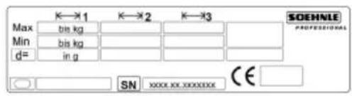

CE Marking
Weighing range

Symbol Protection class II
Max. Maximum load of the weighing range

Article number of the product
Min. Minimum load of the weighing range

Producer of the product
d= Division

Serial number of the scale
7. Product description
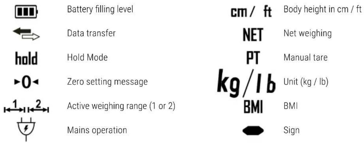
7.1 Connection and device description
Interface RS232 (optional)
This is a communication interface for transferring data to PCs and peripheral devices such as printers.
For further information on the interface, see separate description of the 7835 data interface, Art. No. 470.508.101.
7.2 Operating buttons
| Button Function | Setting mode | |
| On / Off Switches the scale on and off. Cancel setting step or mode. | ||
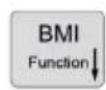
| BMI / Function | Freely programmable function key / reduce value. | Reduce the setting step backward or reduce the value. |
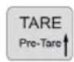
| TARE / Pre-Tare | Tare / Pre-Tare Increase value. | Setting step forward or increase value. |
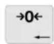
| →0← 0 | Set the scale to zero. | Jump back one menu level and advance one editable decade from right to left. |
| SEND / Menu | Send value or confirm entry. | Save the editing function within the setting step or parameter and jump to the next setting step. |
7. Product description
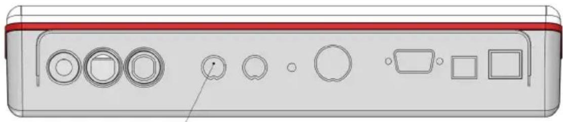
7.3 Display symbols

Display icons without current function*:
Visible when the scale is switched on.

*Provided for future extensions
8. Assembly
8.1 Installation note
You will need the following tools to set up the scale:
- 7835.01.00x: Allen key size 5
- 7835.02.00x: Allen key size 5, screwdriver PZ2
8.2 Installation steps
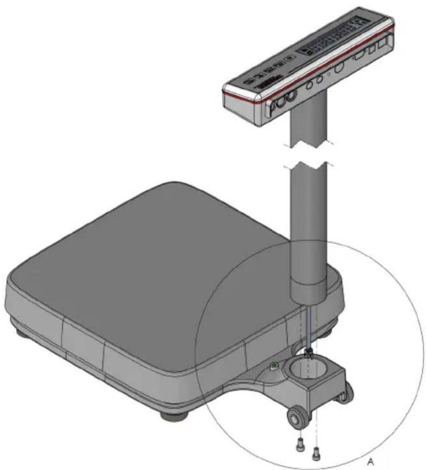
Step 1:
Feed the display cable through the hole in the base plate and insert the tube into the socket in the base plate.
8. Assembly
Step 2:
The display unit with stand tube can be mounted in two different positions.
This determines whether the display can be read by the person on the scale or, if necessary, by the operator in front of the scale.
Position the tube as desired and fasten it with the two cylinder screws supplied.
Place the scale carefully on its side to tighten the screws.

8. Assembly
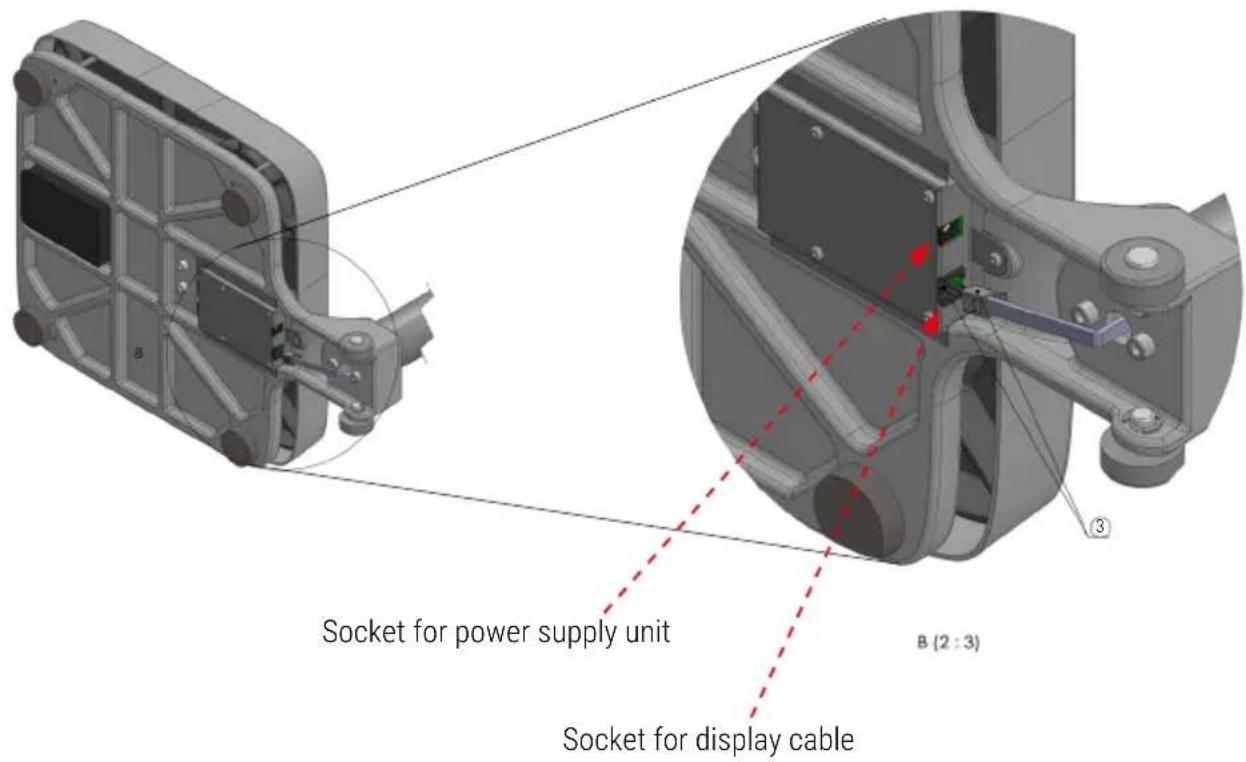
Step 3: Plug the display cable into the socket on the bottom of the scale
For battery operation see steps 4 & 5
For mains operation continue at step 6.
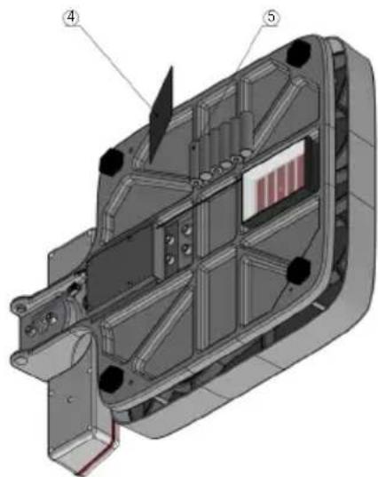
Step 4: (only with battery operation)
Open the battery compartment cover.
Step 5: (only with battery operation)
Insert the six AA batteries supplied.
Ensure correct polarity.
Then close the battery compartment cover again.
Step 6: (only for mains operation)
Plug the optionally available power supply unit into the socket provided (see drawing above).
The scale is now ready to weigh.
8. Assembly
Step 7: Installation height rod (only for 7835.02.00x)
The holders are screwed to the height rod with the countersunk screws. Then the height rod is attached to the tube with the pan-head screws.


9. Commissioning
9.1 Installation note
Before connection, make sure that the required voltage supply according to the type plate corresponds to the local conditions. Protect the unit from shocks, vibrations, strong heat or cold, draughts, chemicals and moisture by selecting a suitable location.
A warm-up period of 30 minutes after switching on stabilises the measured values.
Place the scale on a firm, free and horizontal surface.
Make sure that no cables or other objects are trapped under the scale.
Align the scale by turning the foot screws.
For installation sites in Germany this is fulfilled if the floors comply with the tolerance specifications for ready-to-use floors according to DIN 18202, table 3 line 4. For other countries, the respective applicable national standards can be used as a basis.
9.2 Power supply
Power is supplied by 6x AA batteries LR6 as standard or by the optionally available mains adapter with mains plug (art. no. 2563.45.007).
Type AA batteries can be used.
To obtain a correct charge status display, the option Battery must be activated in UCAL.
See separate description User mode 7835, art. no. 470.702.124.
If required, this document can be requested from Soehnle Industrial Solutions or from your local scale dealer.
10. Operation
10.1 Switch on

With the scale is unloaded, press the on/off key.

During the test routine, the version status is briefly displayed.
This is not an error message.
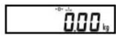
Then the display switches to zero.
The scale is ready to weigh.
10.2 Weighing

Load the scale. The display shows the gross weight.
10.3 Zeroing
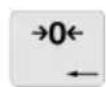
Press the zeroing key to correct small deviations from the zero point, e.g. due to contamination of the balance.
Zero setting range: -1 to +3% of the weighing range.
10.4 Taring
Manual Tare
Place towels or other supports on the weighing platform. Then press the tare key.
The display goes to zero. The display shows "Net" for "Net".
Taring is possible within the entire weighing range.
Manual tare input
You can enter a fixed tare value manually with the manual tare input. (Setting the function key: see separate description User mode 7835, art. no.
470.702.124). If required, this document can be requested from Soehnle Industrial Solutions or from your local scale dealer.


Press the function key
Set the desired fare weight with the fare or function key. Pressing briefly causes the value to be incremented/decremented one by one. With permanent pressure the display runs up or down.


Press the Send key to finally accept the set value.
10. Operation
Tare Info
Press the zeroing key to display the tare info.
If you press briefly, the tare weight is deleted. If you press and hold down until the weight display flashes, the tare weight is displayed and not deleted.

Delete tare
Press the zeroing key to delete the tare.
Intermediate tare function (dialysis function)
An intermediate fare function can be assigned to the function key (see separate description User mode 7835, art. no. 470.702.124). Unknown fare values are added to the existing fare value without changing the net display.

Press the function key to activate the intermediate tare function.
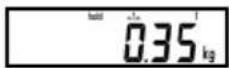
The display shows "hold".
Place additional tare weight on the platform or remove tare weight from the platform.

The new tare value is accepted with the Send key.
10.5 Switching units
Switching units
The weight or length unit (kg/lb or cm/ft) is switched by pressing the function key.
(Setting of the function key: see separate description User mode 7835, art. no. 470.702.124)
10. Operation
10.6 Hold function
The hold function is activated in setting mode (see separate description User mode 470.702.124).

To freeze weight data, the following hold functions are available available as standard. Default is 0^
| Holdmode Function | Cancel function |
| 0 not active | - |
| 1 hold at stand still Unloading the scale | |
10
NOI⊥∀dO
10.7 BMI function
Load the scale.
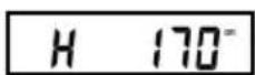
Press the function key. (Default setting of the function key)
The display shows the set body height. The factory setting is 170cm as the standard value (H170cm)
Changes can be made with the BMI / Function and Tare / Pre-Tare keys.

Confirm your entry with the Send key.
The display alternates between the weight and BMI values (display: bl)
Example: bl 26.2 82.8 kg.
Use the function key to change the set body size again.
To exit the BMI function, unload the scale or press the on/off key.
10. Operation
10.8 Small child weighing

An adult person stands on the scale.
The display shows e.g. 82.50 kg . Press the TARE key.
The display goes to 0.00kg The adult person steos down from the scale...

The display shows -82.50kg and places himself on the scales again together with the child.

The weight of the child is displayed as the result, e.g. 7.45 ~kg
10.9 Operation of the height rod
Carefully push the height rod upwards and carefully fold out the extension arm. Then slowly push the unfolded height rod down again until the extension arm rests on the head of the person to be measured. The height in cm can now be read off the attached scale.
Measurements above 131 cm:
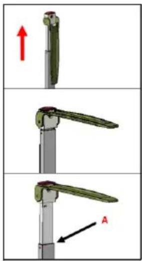
1.Pull out the height rod
2. Position the head piece in horizontal position
3. The reading of the body height can be done at point A
Measurements below 131 cm:
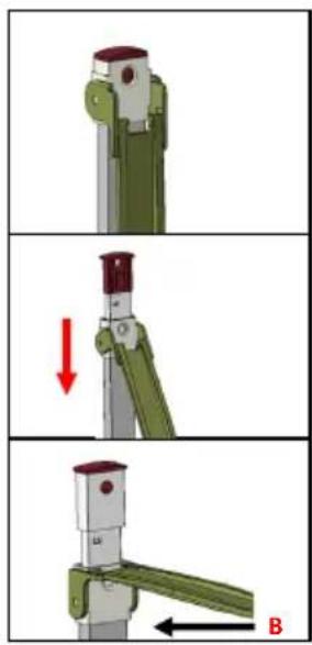
- Fold in the head piece and press the buckle
- Pull the head piece down while pressing the buckle
- The height reading can be taken at point B
10.10 Switch off / End operation safely

Press the on/off key to switch off the scale.
Immediately possible with empty scale and 0-weight display.
Keep the ON/OFF key pressed for 5 seconds when the scale is loaded.
Press the key to switch off the machine. When the mains plug is removed from the socket, all poles of the machine are disconnected from the mains. Operation is now safely terminated.

Notice:
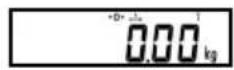
If 0.00kg^ appears on the display, the scale switches off automatically after a preset time.
Press the On/Off key to reactivate the display.
11. Malfunctions - causes and remedies
Display Description Remedy
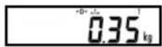
| -0- | The scale automatically resets to zero when switched on. If the scale is outside the intended tolerance range, the display shows -0-. | Unload the scale. Remove any dirt. If the scale does not display zero after a few seconds, please contact your manufacturer's service department. |
| Underload: Only the lower horizontal lines appear in the display field. | Switch off the scale and switch it on again. The zero point is reset automatically. | |
| Overload: The display field only shows the upper Horizontal lines. The maximum weighing range has been exceeded. | If the weight of the person to be weighed exceeds the maximum capacity of the scale, weighing with this model is not possible. | |
| Err 05 | Zeroing limit exceeded or not reached. | Check whether there are any objects on the scale. Remove them and restart the scale. |
| Err 06 | Taring is not possible when the scale is unloaded or overloaded. | Load the scale in the normal range. |
| Err 07 | Printing not possible in case of under- or overload. | Load the scale in the normal range. |
| When the battery symbol is lit continuously: scale is in battery mode. | No error. | |
| ≥ | When the battery symbol flashes: Batteries are discharged. Approx. 30 minutes of operating time remain. | Connect device to mains adapter (optionally available) or change batteries. |
| LO | Battery is empty. | Connect device to mains adapter (optionally available) or change batteries. |
If the errors are not corrected or if error messages not listed here are displayed, please contact the Soehnle Industrial Solutions customer service.
12. Notes on electromagnetic compatibility
| Guidelines and manufacturer's declaration - electromagnetic emissions | ||
| The 7835 series scale is designed for operation in the ELECTRICAL MAGNETIC ENVIRONMENT specified below. The customer or the user of the 7835 scale should ensure that it is used in such an environment. | ||
| Emission measurement | Compliance | Electromagnetic environment - Guideline |
| HF emissions according to CISPR 11 | Group 1 The 7835 scale | uses HF energy exclusively for its internal FUNCTION. Therefore, HF emission is very low and is unlikely to interfere with neighbouring electronic equipment. |
| HF emissions according to CISPR 11 | Class B The 7835 scale | is intended for use in all establishments including domestic establishments and those directly connected to a PUBLIC SUPPLY NETWORK that supplies buildings used for domestic purposes. |
| Harmonics according to IEC 61000-3-2 | Class A The 7835 scale | is intended for use in all establishments including domestic establishments and those directly connected to a PUBLIC SUPPLY NETWORK that supplies buildings used for domestic purposes. |
| Voltage fluctuations / flicker according to IEC 61000-3-3 | fulfilled The 7835 scale | is intended for use in all establishments including domestic establishments and those directly connected to a PUBLIC SUPPLY NETWORK that supplies buildings used for domestic purposes. |
The scale is subject to special precautions regarding EMC and must be installed and commissioned in accordance with the EMC instructions contained in the accompanying documents. Portable and mobile HF communication equipment may affect the scale if the distance is too short.
12. Notes on electromagnetic compatibility
| Guidelines and manufacturer's declaration - electromagnetic immunity | |||
| The 7835 series scale is designed for operation in the ELECTRICAL MAGNETIC ENVIRONMENT specified below. The customer or the user of the 7835 scale should ensure that it is used in such an environment. | |||
| Interference immunity test | IEC 60601 test level | Compliance level | Electromagnetic environment - Guidelines |
| Static electricity discharge (ESD) according to IEC 61000-4-2 | +6 kV contact discharge (indirect) | +6 kV contact discharge | Floors should be made of wood or concrete or be covered with ceramic tiles. If the floor is covered with synthetic material, the relative humidity must be at least 30%. |
| +8 kV Air discharge | +8 kV Air discharge | ||
| Fast transient electrical disturbances/bursts according to IEC 61000-4-5 | +2 kV for power cables | +2 kV for power cables | The quality of the supply voltage should be that of a typical business or hospital environment. |
| +1 kV for input and output lines | +1 kV for input and output lines | ||
| Surges according to IEC 61000-4-5 | +1 kV Voltage outer conductor - outer conductor | +1 kV Voltage outer conductor - outer conductor | The quality of the supply voltage should be that of a typical business or hospital environment. |
| ±1 kV Voltage outer conductor - earth | Not applicable | ||
| Voltage dips, short interruptions and supply voltage fluctuations according to IEC 61000-4-11 | <5% UT for 1/2 period (>95 % collapse) | <5% UT for 1/2 period (>95 % collapse) | The quality of the supply voltage should be that of a typical business or hospital environment. If the user of the 7752 scale requires continued FUNCTION even in the event of power supply interruptions, it is recommended that the 7752 scale be powered from an uninterruptible power supply. |
| 40% UT for 5 period (60 % collapse) | 40% UT for 5 period (60 % collapse) | ||
| 70% UT for 25 period (30 % collapse) | 70% UT for 25 period (30 % collapse) | ||
| <5% UT for 5 s (>95 % collapse) | <5% UT for 5 s (>95 % collapse) | ||
| Magnetic field at the supply frequency (50/60 Hz) according to IEC 61000-4-8 | 3 A/m 3 A/m Magnetic fields at the mains fields at the mains | frequency should correspond to the typical values found in the business and hospital environment. | |
| NOTE: LT is the mains alternating voltage before the test level is applied | |||
12. Notes on electromagnetic compatibility
| Guidelines and manufacturer's declaration - electromagnetic immunity | |||
| The 7835 series scale is designed for operation in the ELECTRICAL MAGNETIC ENVIRONMENT specified below. The customer or the user of the 7835 scale should ensure that it is used in such an environment. | |||
| Interference immunity test | IEC 60601 test level | Compliance level | Electromagnetic environment - Guidelines |
| Conducted HF disturbance variables according to IEC 61000-4-6 Radiated HF disturbance variables to IEC 61000-4-3 | 3 Veff 150 kHz to 80 MHz3 V/m 80 MHz to 2.5 GHz3 V/m 80 MHz to 2.5 GHz | 10 Veff 150 kHz to 80 MHz10V/m 26 MHz to 2,7 GHz | Portable and mobile radios are used at no less distance from the 7835 scale, including cables, than the recommended separation distance calculated according to the equation appropriate to the transmission frequency.Recommended safety distance:d = 0,4 vPd = 0,4 vPfor 80 MHz to 800 MHzd = 0,7 vPfor 800 MHz to 2.7 GHzwhere P is the rated power of the transmitter in watts (W) as specified by the transmitter manufacturer and d is the recommended safety distance in metres (m).The field strength of stationary radio transmitters is lower than the compliance level at all frequencies according to an on-site study.Interference may occur in the vicinity of equipment that bears the following symbol.( )( ) |
| NOTE 1: At 26 MHz and 800 MHz the higher frequency range appliesThese guidelines may not be applicable in all cases. The propagation of electromagnetic sizes are influenced by absorptions and reflections of buildings, objects and people | |||
| a) The field strength of stationary transmitters, such as base stations of radio telephones and mobile land radios, amateur radio stations, AM and FM radio and television transmitters cannot be predicted theoretically with any accuracy. To determine the electromagnetic environment with regard to stationary transmitters, a study of the site should be considered. If the measured field strength at the site where the equipment is used exceeds the above compliance level, the equipment should be observed to verify that it is functioning as intended. If unusual performance characteristics are observed, additional measures may be necessary, such as changing or relocating the equipment.b) Over the frequency range from 150 kHz to 80 MHz, the field strength should be less than 3 V/m. | |||
12. Notes on electromagnetic compatibility
| Recommended safety distances between portable and mobile HF telecommunication devices and the scales of the 7835 series | |||
| The 7835 series scale is designed for operation in the ELECTRICAL MAGNETIC ENVIRONMENT specified below. The customer or the user of the scales type 7835 can thus help to avoid electromagnetic interference by keeping the minimum distance between portable and mobile HF telecommunication devices (transmitters) and the scales type 7835 - depending on the output line of the communication device, as specified below. | |||
| Nominal power of the transmitter W | Safety distance depending on the transmission frequency m | ||
| 150 kHz to 80 MHz | 80 MHz to 800 MHz | 800 MHz to 2,5 GHz | |
| d = 1,2 √P | d = 0,35 √P | d = 0,7 √P | |
| 0,01 | 0,12 | 0,04 | 0,07 |
| 0,1 | 0,38 | 0,11 | 0,22 |
| 1 | 1,20 | 0,35 | 0,70 |
| 10 | 3,79 | 1,11 | 2,21 |
| 100 | 4,0 | 3,50 | 7,00 |
| For transmitters whose rated power is not given in the above table, the distance can be determined using the equation associated with the respective column, where P is the rated power of the transmitter in watts (W) as specified by the transmitter manufacturer. NOTE 1: An additional factor of 10/3 was used to calculate the recommended separation distance of transmitters in the frequency range from 80MHz to 2.5 GHz to reduce the probability that a mobile/portable communication device inadvertently introduced into the patient area will cause interference. NOTE 2: These guidelines may not be applicable in all cases. The propagation of electromagnetic quantities is influenced by absorptions and reflections from buildings, objects and people. | |||
Soehnle Industrial Solutions GmbH
Gaildorfer Straße 6
71522 Backnang
Telefon: +49 7191 / 3453 220
All rights reserved.