TCX102 - Speaker Turbosound - Free user manual and instructions
Find the device manual for free TCX102 Turbosound in PDF.
User questions about TCX102 Turbosound
0 question about this device. Answer the ones you know or ask your own.
Ask a new question about this device
Download the instructions for your Speaker in PDF format for free! Find your manual TCX102 - Turbosound and take your electronic device back in hand. On this page are published all the documents necessary for the use of your device. TCX102 by Turbosound.
USER MANUAL TCX102 Turbosound
Loudspeakers for Portable PA and Installation Applications Quickstart Guide2 TCX series Quick Start Guide
Terminals marked with this symbol carry electrical current of suffi cient magnitude to constitute risk of electric shock. Use only high-quality commercially-available speaker cables with plugs pre-installed. All other installation or modifi cation should be performed only by qualifi ed personnel. This symbol, wherever it appears, alerts you to the presence of uninsulated dangerous voltage inside the enclosure - voltage that may be suffi cient to constitute a risk of shock. This symbol, wherever it appears, alerts you to important operating and maintenance instructions in the accompanying literature. Please read the manual. Caution To reduce the risk of electric shock, do not remove the top cover (or the rear section). No user serviceable parts inside. Refer servicing to qualifi ed personnel. Caution To reduce the risk of fi re or electric shock, do not expose this appliance to rain and moisture. The apparatus shall not be exposed to dripping or splashing liquids and no objects fi lled with liquids, such as vases, shall be placed on the apparatus. Caution These service instructions are for use by qualifi ed service personnel only. To reduce the risk of electric shock do not perform any servicing other than that contained in the operation instructions. Repairs have to be performed by qualifi ed service personnel.
1. Read these instructions.
2. Keep these instructions.
3. Heed all warnings.
4. Follow all instructions.
5. Do not use this apparatus near water.
6. Clean only with dry cloth.
7. Do not block any ventilation
openings. Install in accordance with the manufacturer’s instructions.
8. Do not install near any heat sources
such as radiators, heat registers, stoves, or other apparatus (including amplifi ers) that produce heat.
9. Do not defeat the safety purpose of
the polarized or grounding-type plug. A polarized plug has two blades with one wider than the other. A grounding-type plug has two blades and a third grounding prong. The wide blade or the third prong are provided for your safety. If the provided plug does not fi t into your outlet, consult an electrician for replacement of the obsolete outlet.
10. Protect the power cord from being
walked on or pinched particularly at plugs, convenience receptacles, and the point where they exit from the apparatus.
11. Use only attachments/accessories
specifi ed by the manufacturer.
the cart, stand, tripod, bracket, or table specifi ed by the manufacturer, or sold with the apparatus. When a cart is used, use caution when moving the cart/apparatus combination to avoid injury from tip-over.
13. Unplug this apparatus during lightning
storms or when unused for long periods of time.
14. Refer all servicing to qualifi ed service
personnel. Servicing is required when the apparatus has been damaged in any way, such as power supply cord or plug is damaged, liquid has been spilled or objects have fallen into the apparatus, the apparatus has been exposed to rain or moisture, does not operate normally, or has been dropped.
15. The apparatus shall be connected to
a MAINS socket outlet with a protective earthing connection.
16. Where the MAINS plug or an appliance
coupler is used as the disconnect device, the disconnect device shall remain readily operable.
17. Correct disposal of
this product: This symbol indicates that this product must not be disposed of with household waste, according to the WEEE Directive (2012/19/EU) and your national law. This product should be taken to a collection center licensed for the recycling of waste electrical and electronic equipment (EEE). The mishandling of this type of waste could have a possible negative impact on the environment and human health due to potentially hazardous substances that are generally associated with EEE. At the same time, your cooperation in the correct disposal of this product will contribute to the effi cient use of natural resources. For more information about where you can take your waste equipment for recycling, please contact your local city offi ce, or your household waste collection service. LEGAL DISCLAIMER MUSIC Group accepts no liability for any loss which may be suffered by any person who relies either wholly or in part upon any description, photograph, or statement contained herein. Technical specifi cations, appearances and other information are subject to change without notice. All trademarks are the property of their respective owners. MIDAS, KLARK TEKNIK, LAB.GRUPPEN, LAKE, TANNOY, TURBOSOUND, TC ELECTRONIC,
BESCHRÄNKTE GARANTIE
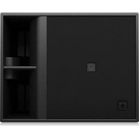
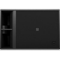
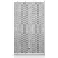
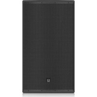
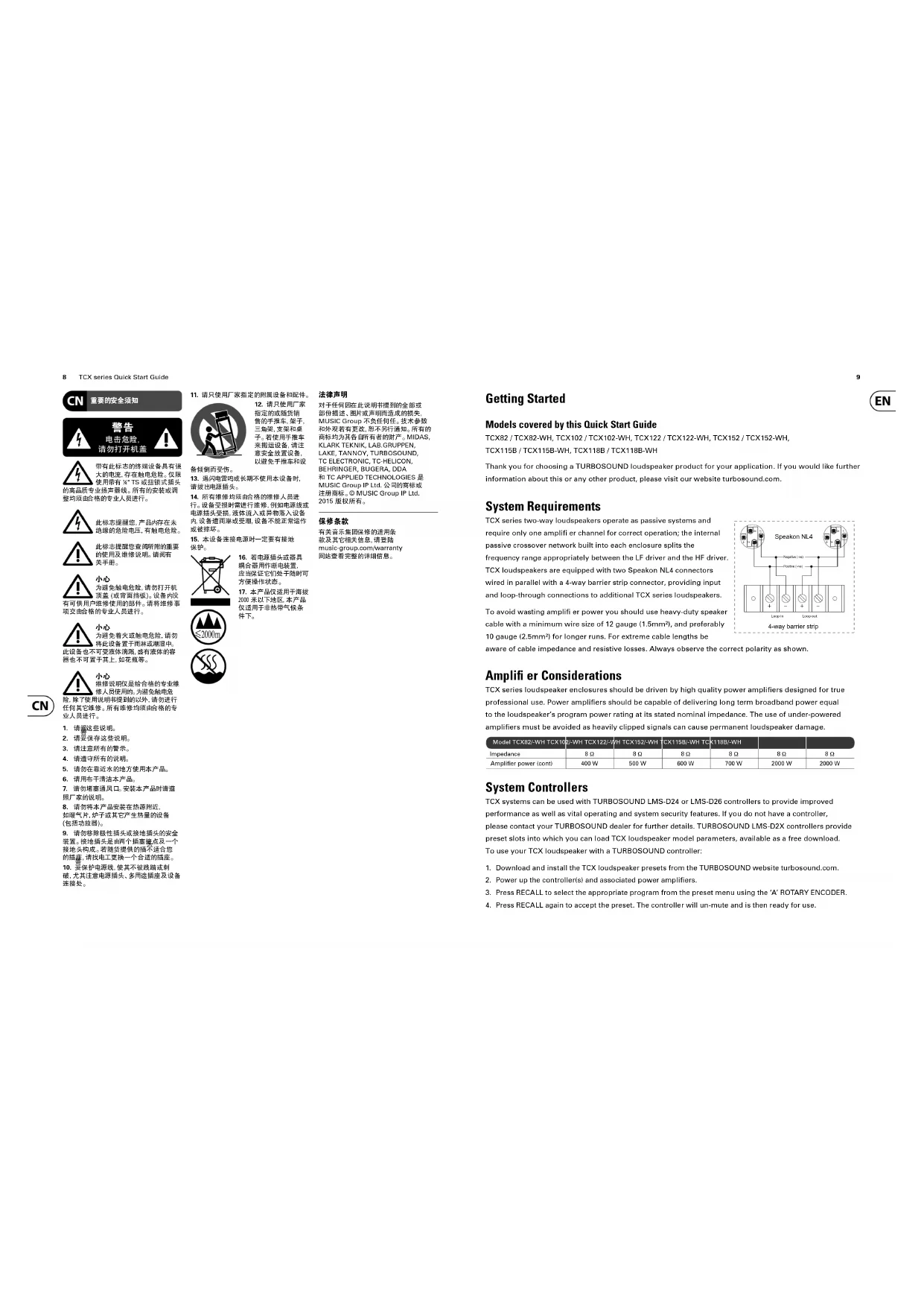
Getting Started Models covered by this Quick Start Guide TCX82 / TCX82-WH, TCX102 / TCX102-WH, TCX122 / TCX122-WH, TCX152 / TCX152-WH, TCX115B / TCX115B-WH, TCX118B / TCX118B-WH Thank you for choosing a TURBOSOUND loudspeaker product for your application. If you would like further information about this or any other product, please visit our website turbosound.com. System Requirements TCX series two-way loudspeakers operate as passive systems and require only one amplifi er channel for correct operation; the internal passive crossover network built into each enclosure splits the frequency range appropriately between the LF driver and the HF driver. TCX loudspeakers are equipped with two Speakon NL4 connectors wired in parallel with a 4-way barrier strip connector, providing input and loop-through connections to additional TCX series loudspeakers. To avoid wasting amplifi er power you should use heavy-duty speaker cable with a minimum wire size of 12 gauge (1.5mm²), and preferably 10 gauge (2.5mm²) for longer runs. For extreme cable lengths be aware of cable impedance and resistive losses. Always observe the correct polarity as shown. Amplifi er Considerations TCX series loudspeaker enclosures should be driven by high quality power amplifi ers designed for true professional use. Power amplifi ers should be capable of delivering long term broadband power equal to the loudspeaker’s program power rating at its stated nominal impedance. The use of under-powered amplifi ers must be avoided as heavily clipped signals can cause permanent loudspeaker damage. Model TCX82/-WH TCX102/-WH TCX122/-WH TCX152/-WH TCX115B/-WH TCX118B/-WH Impedance 8 Ω 8 Ω 8 Ω 8 Ω 8 Ω 8 Ω Amplifi er power (cont) 400 W 500 W 600 W 700 W 2000 W 2000 W System Controllers TCX systems can be used with TURBOSOUND LMS-D24 or LMS-D26 controllers to provide improved performance as well as vital operating and system security features. If you do not have a controller, please contact your TURBOSOUND dealer for further details. TURBOSOUND LMS-D2X controllers provide preset slots into which you can load TCX loudspeaker model parameters, available as a free download. To use your TCX loudspeaker with a TURBOSOUND controller:
1. Download and install the TCX loudspeaker presets from the TURBOSOUND website turbosound.com.
2. Power up the controller(s) and associated power amplifi ers.
3. Press RECALL to select the appropriate program from the preset menu using the ‘A’ ROTARY ENCODER.
4. Press RECALL again to accept the preset. The controller will un-mute and is then ready for use.
Networking Capability with LMS series Controllers
- • LMS-D2X controllers are designed to offer control and monitoring of system parameters over a BvNet network in real time using a PC and TurboDrive software. The controllers are equipped with network cards to allow the building of comprehensive networked loudspeaker systems.
- • Download the TurboDrive software from the supplied CD or from the TURBOSOUND website turbosound.com and follow the installation instructions.
- • Install the drivers. If connecting via RS232 there is no need to install drivers. If connecting via USB install the USB drivers which can be found on the CD that came with your Linea Research USB interface.
- • Networking multiple devices to a PC: BvNet is the method of connecting multiple devices and this is done with the Linea Research USB & RS232 Interface (available from TURBOSOUND). The interface enables devices to be connected to a PC either using RS232 or using USB. EIA485 is the network protocol among the networked devices and is carried over CAT5-type cables. It works with the following: PC with Windows NT, Windows 2000, Windows XP, or Windows Vista operating systems, or with Pentium processor, or CD ROM drive or internet access, RS232 or USB port.*
- • RS232: Connect your computer to the BvNet interface using a standard 9-pin serial cable. External power is required for RS232 operation and this should be provided by the Linea Research Accessory Power Supply.
- • USB: Connect your computer to the BvNet interface using a USB Type A to USB Type B cable. External power is not required when using USB.
- • Connect networked devices via RJ45 CAT5 cables.
- • Launch the TurboDrive software.
- • Application Authorisation: TurboDrive prompts for an Authorisation Code on the fi rst launch which is PJLUWZ.
- • Select the COM port from Network > Com Port.
- • Click the Online toolbar button.
- • Click on one of the devices that appear in the tree view to Launch the panel.
- • When the progress bar indicates ready, adjust the controls as required.
- • Please refer to the TurboDrive User Guide for further information on networking. Mounting and Fixing TCX series cabinets are designed with multiple internal rigging points to suit many possible mounting methods in permanent installations and portable situations. The table below summarises the mounting accessories available for each model. Model Wall mount Ceiling mount Eyebolts Pole bracketTCX82/-WH WB-20 CB-20 EB-10-40 PB-55TCX102/-WHWB-20 CB-20 EB-10-40 PB-55TCX122/-WHWB-20 CB-20 EB-10-40 PB-55TCX152/-WHWB-20 CB-20 EB-10-40 PB-55TCX115B/-WHN/A N/A EB-10-40 N/ATCX118B/-WHN/A N/A EB-10-40 N/A*Windows NT, Windows 2000, Windows XP and Windows Vista are either registered trademarks or trademarks of Microsoft Corporation in the United States and/or other countries. Pentium is a trademark of Intel Corporation in the U.S. and/or other countries. Use with Speaker Poles and Speaker Stands Use an industry standard speaker pole on top of a bass cabinet to raise the mid/high cabinets to above head height for better audience coverage. For portable use remove the plastic bung covering the pole mount socket. Fit the speaker pole into the pole mount socket on the TCX bass cabinet and mount the TCX two-way cabinet to the top of the pole. Always use caution when lifting the loudspeaker. Wall Brackets
1. Separate the component parts of the bracket into the wall plate and
speaker plate assemblies by removing the nylock nut underneath the wall plate horizontal lug.
2. Remove the countersunk bolts on the rear panel of the cabinet and
attach the speaker plate to the cabinet with the bolts supplied.
3. Fix the wall plate in the venue using appropriate fi xings
(not supplied), ensuring that the cable access hole is towards the top.
4. Lift the loudspeaker on to the wall plate and locate the large
captive bolt welded to the speaker plate through the wall plate lug. Re-assemble the bracket parts, adjust the aim of the loudspeaker and tighten all bolts. Ceiling Brackets
1. Separate the component parts of the bracket into the ceiling plate and
speaker plate assemblies by removing the nylock nut underneath the wall plate lug.
2. Remove the countersunk bolts on the rear panel of the cabinet and
attach the speaker plate to the cabinet with the bolts supplied.
3. Fix the ceiling plate in the venue using appropriate fi xings
(not supplied). Lift the loudspeaker on to the ceiling plate and re-assemble the bracket fi xings, adjust the aim of the loudspeaker and tighten all bolts. Pole Brackets TCX series mid-high cabinets equipped with a recessed pole mount socket can be wall mounted with the generic TPOLE-BK pole bracket. Fix the bracket in the venue using appropriate wall fi xings, mount the loudspeaker on to the spigot, and aim the loudspeaker as required. Tighten the pole bracket grub screw to lock the loudspeaker and prevent unauthorised removal. Illustrated: TCX152 on a WB-55 wall bracket Illustrated: TCX122 on a CB-55 wall bracket12 TCX series Quick Start Guide
OmniMount Brackets The internal rigging points are also compatible with OmniMount series 120 wall and ceiling brackets. To mount TCX cabinets with OmniMount brackets follow the instructions provided with the brackets. Suspending with Eyebolts TCX cabinets can be suspended using optional eyebolts coupled to the internal rigging points provided on the top, bottom and sides and back. The simplest method is to use the two rigging points on the top and a single pull-back rigging point in the centre of the rear panel. Remove the appropriate countersunk screws and replace them with shoulder eyebolts, which must have a thread length of at least 18 mm. Use the rear rigging point to angle the cabinet for optimum room coverage. Cabinets may be hung upside down if required. IMPORTANT NOTE: The mounting of a permanently installed sound system may be dangerous unless undertaken by qualifi ed personnel with the required experience and certifi cation to perform the necessary tasks. Walls, fl oors or ceilings must be capable of safely and securely supporting the actual load. The mounting accessory used must be safely and securely fi xed both to the loudspeaker and to the wall, fl oor or ceiling. When mounting rigging components on walls, fl oors or ceilings, ensure that all fi xings and fasteners used are of an appropriate size and load rating. Wall and ceiling claddings, and the construction and composition of walls and ceilings, all need to be taken into account when determining whether a particular fi xing arrangement can be safely employed for a particular load. Cavity plugs or other specialist fi xings, if required, must be of an appropriate type, and must be fi tted and used in accordance with the maker’s instructions. The operation of your speaker cabinet as part of a fl own system, if installed incorrectly and improperly, can potentially expose persons to serious health risks and even death. In addition, please ensure that electrical, mechanical and acoustic considerations are discussed with qualifi ed and certifi ed (by local state or national authorities) personnel prior to any installation or fl ying. Make sure that speaker cabinets are set up and “fl own” by qualifi ed and certifi ed personnel only, using dedicated equipment and original parts and components delivered with the unit. If any parts or components are missing please contact your Dealer before attempting to set up the system. Be sure to observe the local, state and other safety regulations applicable in your country. MUSIC Group, including the MUSIC Group companies listed on the enclosed “Service Information Sheet”, assume no liability for any damage or personal injury resulting from improper use, installation or operation of the product. Regular checks must be conducted by qualifi ed personnel to ensure that the system remains in a secure and stable condition. Make sure that, where the speaker is fl own, the area underneath the speaker is free of human traffi c. Do not fl y the speaker in areas which can be entered or used by members of the public. Speakers create a magnetic fi eld, even if not in operation. Therefore, please keep all materials which can be affected by such fi elds (discs, computers, monitors etc) at a safe distance. A safe distance is usually between 1 and 2 metres. Servicing and Driver Removal
1. Place the cabinet on its back on a suitable work surface. Remove the eight Pozidrive countersunk screws
that hold the grille in place and set the grille aside (fi g 1).
2. Remove the M5 hex head bass driver fi xings screws (fi g 2).
3. Disconnect and remove the bass driver, making a note of the polarity for later reconnection (fi g 3).
5. Lift out the horn and compression driver assembly. Disconnect the cables from the compression driver,
making a note of the polarity for later reconnection (fi g 5).
6. Reinstatement is a simple reversal of the above process. Reconnect the compression driver cables,
observing the correct polarity (white cable to the +ve terminal, green/white cable to the –ve terminal).
7. Replace the horn and driver in the cabinet.
8. Replace the horn fi xing screws and tighten.
9. Reconnect the bass driver cables, observing the correct polarity (brown cable to the red +ve terminal,
blue cable to the black –ve terminal) and reinstate the driver in the cabinet. Replace and tighten the driver fi xing screws.
10. Replace the grille and phase check the cabinet before use.14
Rotating the HF Horn Pattern The high frequency horn in all TCX two-way models can be rotated through 90° in order to swap the horizontal and vertical dispersion patterns, particularly useful to retain the wide horizontal dispersion when the cabinet is installed horizontally in venues with limited ceiling height.
1. Remove the loudspeaker grille as before.
2. Remove the M5 hex head HF horn fi xing screws.
3. Lift the horn / driver assembly out, rotate the horn as
necessary to achieve the desired coverage pattern and replace it in the cabinet.
4. Replace the horn fi xing screws and tighten.
5. Replace the grille and phase check the cabinet before use.
EASE Data EASE data is available for TCX series loudspeakers to enable software simulation of audio coverage installation projects. Please visit turbosound.com for a free EASE data download. TCX152 (WH) TCX118B (WH) TCX115B (WH) System Frequency response 85 Hz - 18 kHz ±3 dB 55 Hz - 20 kHz -10 dB 35 Hz - 125 Hz ±3 dB 25 Hz - 170 Hz -10 dB 35 Hz - 125 Hz ±3 dB 28 Hz - 170 Hz -10 dB Nominal dispersion 90° H x 60° V @ -6 dB points Half space Half space Power handling (IEC) 350 W continuous, 1400 W peak 1,000 W continuous, 4,000 W peak 1,000 W continuous, 4000 W peak Sensitivity 99 dB (1 W @ 1 m) 97 dB (1 W @ 1 m) 95 dB (1 W @ 1 m) Maximum SPL 125 dB continuous, 131 dB peak 127 dB continuous, 133 dB peak 125 dB continuous, 131 dB peak Impedance 8 Ω 8 Ω 8 Ω Components 1 x 15" (381 mm) LF driver 1 x 1" (25 mm) HF compression driver 1 x 18" (457 mm) LF driver 1 x 15" (380 mm) LF driver Enclosure Connectors 2 x Neutrik speakON NL4, 1 x barrier strip terminals 2 x Neutrik speakON NL4, 1 x barrier strip terminals 2 x Neutrik speakON NL4, 1 x barrier strip terminals Wiring Pins 1+ / 1- input, pins 2+ / 2- link Pins 1+ / 1- input, pins 2+ / 2- link Pins 1+ / 1- input, pins 2+ / 2- link Dimensions HWD 652 x 466 x 422 mm (25.6 x 18.3 x 16.7") 660 x 560 x 660 mm (26.0 x 22.0 x 26.0") 600 x 499 x 600 mm (23.6 x 19.7 x 23.6") Net weight
23.5 kg (51.8 lbs) 38.6 kg (85.1 lbs) 34.0 kg (75.0 lbs)
Construction 15 mm (
") birch plywood Finish Semi matt black paint (white optional) Semi matt black paint (white optional) Semi matt black paint (white optional) Grille Powder coated perforated steel Powder coated perforated steel Powder coated perforated steel Flying hardware M10 x 9, M8 x 4, M6 x 4 Points M10 x 8 Points M10 x 8 Points TCX122 (WH) TCX102 (WH) TCX82 (WH) System Frequency response 100 Hz - 18 kHz ±3 dB 68 Hz - 20 kHz -10 dB 100 Hz - 20 kHz ±3 dB 68 Hz - 20 kHz -10 dB 100 Hz - 20 kHz ±3 dB 70 Hz - 20 kHz -10 dB Nominal dispersion 90° H x 60° V @ -6 dB points 90° H x 60° V @ -6 dB points 90° H x 60° V @ -6 dB points Power handling (IEC) 300 W continuous, 1,200 W peak 250 W continuous, 1000 W peak 200 W continuous, 800 W peak Sensitivity 97 dB (1 W @ 1 m) 95 dB (1 W @ 1 m) 94 dB (1 W @ 1 m) Maximum SPL 122 dB continuous, 128 dB peak 119 dB continuous, 125 dB peak 117 dB continuous, 123 dB peak Impedance 8 Ω 8 Ω 8 Ω Components 1 x 12" (305 mm) LF driver 1 x 1" (25 mm) HF compression driver 1 x 10" (254 mm) LF driver 1 x 1" (25 mm) HF compression driver 1 x 8" (203 mm) LF driver 1 x 1" (25 mm) HF compression driver Enclosure Connectors 2 x Neutrik speakON NL4, 1 x barrier strip terminals 2 x Neutrik speakON NL4, 1 x barrier strip terminals 2 x Neutrik speakON NL4, 1 x barrier strip terminals Wiring Pins 1+ / 1- input, pins 2+ / 2- link Pins 1+ / 1- input, pins 2+ / 2- link Pins 1+ / 1- input, pins 2+ / 2- link Dimensions HWD 552 x 406 x 368 mm (21.8 x 15.9 x 14.5") 488 x 366 x 332 mm (19.2 x 14.4 x 13.0") 408 x 308 x 280 mm (16.0 x 12.1 x 11.0") Net weight
18.3 kg (40.2 lbs) 15.1 kg (33.3 lbs) 10.3 kg (22.7 lbs)
Construction 15 mm (
") birch plywood Finish Semi matt black paint (white optional) Semi matt black paint (white optional) Semi matt black paint (white optional) Grille Powder coated perforated steel Powder coated perforated steel Powder coated perforated steel Flying hardware M10 x 9, M8 x 4, M6 x 4 Points M10 x 9, M8 x 4, M6 x 4 Points M10 x 9, M8 x 4, M6 x 4 Points Technical Specifi cations16 TCX series Quick Start Guide
1. Register online. Please register your
new MUSIC Group equipment right after you purchase it by visiting turbosound. com. Registering your purchase using our simple online form helps us to process your repair claims more quickly and effi ciently. Also, read the terms and conditions of our warranty, if applicable.
2. Malfunction. Should your MUSIC Group
Authorized Reseller not be located in your vicinity, you may contact the MUSIC Group Authorized Fulfi ller for your country listed under “Support” at turbosound. com. Should your country not be listed, please check if your problem can be dealt with by our “Online Support” which may also be found under “Support” at turbosound. com. Alternatively, please submit an online warranty claim at turbosound. com BEFORE returning the product.
3. Power Connections. Before plugging
the unit into a power socket, please make sure you are using the correct mains voltage for your particular model. Faulty fuses must be replaced with fuses of the same type and rating without exception. Important information Other important information